TEL:+86 132 6656 7067





100 Gigabit Ethernet connectivity is widely used in telecommunications aggregation, enterprise backbone networks, data center switching, and high-capacity access infrastructure. ADTRAN supports 100G QSFP28 optical transceivers for different fiber environments, including short-reach multimode and longer-reach single-mode connections.
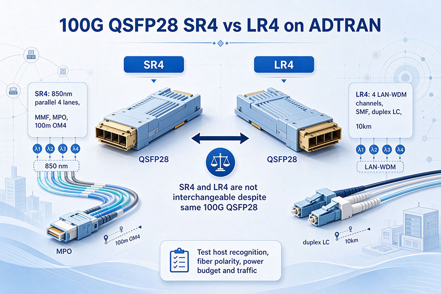
Two important optical interfaces are 100GBASE-SR4 and 100GBASE-LR4. Both use the QSFP28 form factor and support a nominal data rate of 100 Gbps, but their optical architectures are substantially different. SR4 uses four parallel optical channels over multimode fiber, while LR4 combines four wavelength channels for transmission over duplex single-mode fiber.
When deploying ADTRAN 100G QSFP28 modules or compatible third-party transceivers, engineers must verify host-device support, optical specifications, fiber infrastructure, connector configuration, and end-to-end interoperability. A matching QSFP28 form factor alone does not guarantee successful operation.
1. Overview of ADTRAN 100G QSFP28 SR4 and LR4 Modules
ADTRAN offers 100G QSFP28 optical modules for different network applications. SR4 and LR4 are two representative interfaces with different transmission architectures.
| Parameter | 100GBASE-SR4 | 100GBASE-LR4 |
|---|---|---|
| ADTRAN example part number | 1445510F1C | 1445510F2C |
| Form factor | QSFP28 | QSFP28 |
| Data rate | 100 Gbps | 100 Gbps |
| Optical architecture | 4 parallel optical channels | 4 LAN-WDM wavelength channels |
| Lane rate | 4 × 25 Gbps class | 4 × 25 Gbps class |
| Wavelength | 850 nm | Four wavelengths around 1295–1310 nm |
| Fiber type | Multimode fiber | Single-mode fiber |
| Connector | MPO | Duplex LC |
| Typical specified reach | 100 m over OM4 | 10 km over single-mode fiber |
| Application | Short-reach data center and enterprise links | Campus, aggregation, and longer-distance links |
ADTRAN's SR4 documentation identifies part number 1445510F1C and specifies 100GBASE-SR4 operation over multimode fiber, with a distance of up to 100 meters over OM4. Its LR4 documentation identifies 1445510F2C for 100GBASE-LR4 operation over single-mode fiber up to 10 km.
2. ADTRAN 100GBASE-SR4 QSFP28 Compatibility
100GBASE-SR4 is designed for short-distance 100 Gigabit Ethernet connections over multimode fiber. It uses four parallel transmit channels and four parallel receive channels, each operating at approximately 25 Gbps.
2.1 100GBASE-SR4 Optical Specifications
| Parameter | Typical Specification |
|---|---|
| Data rate | 100 Gbps |
| Form factor | QSFP28 |
| Optical standard | 100GBASE-SR4 |
| Wavelength | 850 nm |
| Optical channels | 4 transmit + 4 receive |
| Channel rate | Approximately 25 Gbps per lane |
| Fiber type | Multimode fiber |
| Connector | MPO/MTP |
| ADTRAN documented reach | Up to 100 m over OM4 |
The ADTRAN 1445510F1C SR4 transceiver uses a four-channel VCSEL transmitter array and a four-channel PIN photodiode receiver array. Each optical channel carries approximately 25 Gbps, providing an aggregate 100 Gbps connection.
2.2 Multimode Fiber Requirements
SR4 is designed for multimode fiber, and the supported distance depends on the fiber grade and link characteristics.
| Fiber Type | Typical 100GBASE-SR4 Reach | Application |
|---|---|---|
| OM3 | Up to 70 m | Short-reach enterprise and data center links |
| OM4 | Up to 100 m | Higher-bandwidth multimode infrastructure |
These are representative SR4 reach values. The actual installation must comply with the transceiver specification and the fiber plant's performance characteristics. ADTRAN's 1445510F1C documentation specifically identifies a 100-meter reach over OM4 fiber.
2.3 MPO Connector and Fiber Polarity
Unlike duplex LC interfaces, SR4 uses an MPO connector to carry multiple parallel optical paths through one connector assembly. The standard SR4 arrangement uses four transmit fibers and four receive fibers.
Correct fiber polarity is essential. The transmit channels at one end must connect to the corresponding receive channels at the opposite end. An incorrect MPO polarity arrangement can prevent the link from establishing even when both transceivers are recognized by their host devices.
Before installation, verify:
MPO connector type and fiber count.
Correct polarity for the SR4 channel arrangement.
Compatibility between the transceiver and the installed fiber trunk.
Fiber grade and supported transmission distance.
Connector cleanliness and insertion loss.
3. ADTRAN 100GBASE-LR4 QSFP28 Compatibility
100GBASE-LR4 is designed for 100 Gigabit Ethernet transmission over single-mode fiber. Unlike SR4, which uses parallel optical paths, LR4 combines four wavelength channels into a single optical path through wavelength-division multiplexing.
3.1 100GBASE-LR4 Optical Specifications
| Parameter | Typical Specification |
|---|---|
| Data rate | 100 Gbps |
| Form factor | QSFP28 |
| Optical standard | 100GBASE-LR4 |
| Optical architecture | 4-channel LAN-WDM |
| Channel rate | Approximately 25 Gbps per lane |
| Wavelength range | Four channels around 1295, 1300, 1304, and 1309 nm |
| Fiber type | Single-mode fiber |
| Connector | Duplex LC |
| Maximum specified reach | Up to 10 km |
ADTRAN's 1445510F2C LR4 documentation specifies four LAN-WDM optical channels, each operating at approximately 25 Gbps. The four channels are multiplexed into one optical signal for transmission over single-mode fiber.
3.2 LAN-WDM Wavelength Configuration
100GBASE-LR4 uses four wavelength channels within the 1310 nm region. Representative channel ranges in ADTRAN's documentation are:
| Optical Lane | Transmit Wavelength Range |
|---|---|
| Lane 1 | 1294.53–1296.59 nm |
| Lane 2 | 1299.02–1301.09 nm |
| Lane 3 | 1303.54–1305.63 nm |
| Lane 4 | 1308.09–1310.19 nm |
These channels are combined through an optical multiplexer inside the transceiver and separated by the receiver. This architecture allows four data channels to travel over a conventional duplex single-mode fiber connection.
3.3 Single-Mode Fiber and LC Connectivity
LR4 uses duplex LC connectors and single-mode fiber, typically 9/125 μm fiber. One fiber carries the combined transmit signal, while the other carries the incoming signal.
For an LR4 installation, verify:
Single-mode fiber compatibility.
Correct duplex LC connector configuration.
TX/RX fiber polarity.
Total optical path loss.
Receiver sensitivity and overload limits.
Maximum supported transmission distance.
ADTRAN's LR4 documentation specifies operation up to 10 km over single-mode fiber. The actual link must remain within the module's optical power budget.
4. ADTRAN 100G QSFP28 SR4 vs LR4: Key Differences
SR4 and LR4 are both 100G QSFP28 interfaces, but they address different fiber infrastructures and link distances.
| Comparison | 100GBASE-SR4 | 100GBASE-LR4 |
|---|---|---|
| ADTRAN example part number | 1445510F1C | 1445510F2C |
| Data rate | 100 Gbps | 100 Gbps |
| Optical channels | 4 parallel channels | 4 wavelength channels |
| Wavelength | 850 nm | LAN-WDM around 1310 nm |
| Fiber type | Multimode | Single-mode |
| Connector | MPO/MTP | Duplex LC |
| Reach | 100 m over OM4 | 10 km over SMF |
| Transmission architecture | Parallel optics | Wavelength multiplexing |
| Typical deployment | Data center and short-distance links | Campus and longer-distance network links |
5. ADTRAN Host Device and QSFP28 Compatibility
Optical interoperability is only one part of a successful deployment. The ADTRAN host device must also support the selected QSFP28 module.
ADTRAN's Pluggable Optics Compatibility Matrix lists supported QSFP28 transceivers and identifies compatible equipment families. For example, the matrix includes 100G SR4 part number 1445510F1C and LR4 part number 1445510F2C, together with their supported Total Access 5000 equipment configurations.
Compatibility should be checked against the exact host platform, not assumed across all ADTRAN products.
5.1 Host Compatibility Checklist
Before installing an ADTRAN or third-party QSFP28 module, confirm:
The equipment has a QSFP28 port supporting 100G operation.
The selected SR4 or LR4 interface is supported by the host.
The module part number appears in the applicable compatibility documentation.
The host software and firmware meet the documented requirements.
The module's power consumption and thermal characteristics are suitable.
The device can access the module's identification and diagnostic information where required.
ADTRAN provides an official Pluggable Optics Compatibility Matrix. It should be consulted alongside the hardware documentation for the specific ADTRAN platform.
5.2 Manufacturer Certification and Third-Party Modules
Some ADTRAN QSFP28 product documentation specifies the use of ADTRAN-supplied modules for compliance certification and states that system integrity cannot be certified with other QSFP28 modules.
This distinction matters when evaluating third-party compatible optics. A third-party module may be designed with matching optical specifications and may operate successfully in a particular test environment, but this does not automatically make it an officially ADTRAN-certified component.
Network operators should distinguish between functional interoperability, documented host compatibility, and manufacturer certification. These are related but separate validation results.
6. Can ADTRAN 100G SR4 and LR4 Work with Third-Party Modules?
ADTRAN-compatible 100G SR4 or LR4 modules can potentially interoperate with third-party transceivers when both ends use compatible optical standards and their respective host devices support the installed modules.
For SR4, both ends should use compatible 100GBASE-SR4 optical interfaces over multimode fiber. For LR4, both ends should use compatible 100GBASE-LR4 interfaces over single-mode fiber.
| Interoperability Scenario | Expected Compatibility Conditions |
|---|---|
| ADTRAN SR4 to third-party SR4 | Matching 850 nm SR4 interface, multimode fiber, MPO polarity, and host support |
| ADTRAN LR4 to third-party LR4 | Matching LAN-WDM LR4 interface, single-mode fiber, duplex LC, and host support |
| ADTRAN SR4 to third-party LR4 | Not a standard direct optical pairing |
| ADTRAN LR4 to third-party SR4 | Not a standard direct optical pairing |
Matching the nominal 100G data rate is not sufficient. The optical standard, wavelength configuration, fiber type, and connector arrangement must also match.
7. ADTRAN 100G QSFP28 Compatibility Testing Procedure
A structured test process helps verify both host recognition and end-to-end optical interoperability before deploying a module in a production network.
7.1 Step 1: Identify the ADTRAN Host Platform
Record the exact ADTRAN equipment model, hardware revision, QSFP28 port number, and software version. Confirm that the selected port supports 100G QSFP28 operation and the intended optical interface.
7.2 Step 2: Verify the Transceiver Part Number
Confirm the module's exact part number and specification.
1445510F1C: ADTRAN 100GBASE-SR4, 850 nm, multimode fiber, MPO connector, up to 100 m over OM4.
1445510F2C: ADTRAN 100GBASE-LR4, LAN-WDM, single-mode fiber, duplex LC connector, up to 10 km.
Other ADTRAN LR4 variants, such as 1445510F2, should be checked separately because suffixes can indicate different product configurations or operating conditions.
7.3 Step 3: Verify Fiber and Connector Compatibility
For SR4, verify the multimode fiber grade, MPO connector, fiber polarity, and channel mapping.
For LR4, verify the single-mode fiber path, duplex LC connectors, and correct TX/RX polarity.
Inspect and clean the optical connectors before connecting the modules. Contamination can increase insertion loss and cause unstable high-speed links.
7.4 Step 4: Check Host Recognition
Install the QSFP28 module in the target ADTRAN device and check whether the host recognizes it. Where supported, review the module identification, vendor information, interface state, and digital diagnostic monitoring values.
Useful diagnostic information may include:
Module vendor and part number.
Module temperature and supply voltage.
Transmitter optical power.
Receiver optical power.
Per-lane diagnostic information, where available.
Interface status and reported operating speed.
Available diagnostic fields depend on the transceiver and host platform.
7.5 Step 5: Establish the Optical Link
Connect the ADTRAN module to a compatible transceiver at the opposite end of the fiber link.
For SR4, confirm the MPO polarity and correct parallel-fiber mapping. For LR4, confirm duplex LC polarity and the single-mode fiber path.
Verify that the interface reaches an operational state and that both devices report the expected 100G link speed.
7.6 Step 6: Perform Traffic and Error Testing
A link-up indication does not prove complete interoperability. Perform traffic testing to verify that the connection can transfer data reliably under the intended operating conditions.
Review available interface counters and diagnostic information for:
CRC or frame errors.
Packet drops and transmission errors.
Link flaps or unexpected interface resets.
Abnormal optical power readings.
Lane-related errors where diagnostic information is available.
For production networks, testing should include representative traffic and an appropriate observation period to identify intermittent problems.
8. Common ADTRAN 100G SR4 and LR4 Compatibility Issues
| Potential Issue | Typical Symptom | Validation Focus |
|---|---|---|
| Unsupported QSFP28 module | Module not recognized or port remains inactive | Check host support and part number |
| SR4/LR4 mismatch | No optical link | Verify matching optical standards |
| Incorrect fiber type | Link fails or performs unreliably | Use MMF for SR4 and SMF for LR4 |
| Incorrect MPO polarity | SR4 optical channels cannot communicate | Verify MPO polarity and lane mapping |
| Incorrect LC polarity | LR4 transmit and receive paths do not connect | Check duplex fiber TX/RX connections |
| Excessive insertion loss | Low receiver power or unstable link | Inspect connectors and measure link loss |
| Receiver overload | Optical input exceeds the receiver limit | Check receiver overload specifications |
| Thermal or power limitations | Module warnings or unstable operation | Verify host power and temperature support |
| Third-party coding issue | Module is rejected by the host | Check vendor coding and platform support |
When troubleshooting, separate host recognition problems from optical link problems. A module that is not accepted by the host may never reach the stage of optical communication testing. If both modules are recognized but the link remains down, investigate fiber type, connector polarity, optical power, and interface configuration.
9. Choosing ADTRAN 100G QSFP28 SR4 or LR4
The most suitable interface depends on the network distance, installed fiber infrastructure, and host-device requirements.
| Network Requirement | Suitable Interface |
|---|---|
| Short-distance 100G connection over OM4 fiber | 100GBASE-SR4 |
| Data center switch-to-switch link within SR4 reach | 100GBASE-SR4 |
| Longer-distance connection over single-mode fiber | 100GBASE-LR4 |
| Campus backbone connection within 10 km | 100GBASE-LR4 |
| Existing MPO multimode infrastructure | 100GBASE-SR4, subject to polarity and reach |
| Existing duplex LC single-mode infrastructure | 100GBASE-LR4 |
When replacing an existing transceiver, the original optical interface should normally be preserved unless the fiber infrastructure and network design are also being changed. Replacing SR4 with LR4, or vice versa, requires more than changing the module; the fiber path and connector arrangement must support the new interface.
C-LIGHT provides a range of optical transceiver solutions for enterprise, telecommunications, and data center networks. When selecting a compatible 100G QSFP28 module, provide the equipment model, original transceiver part number, optical standard, fiber type, and required transmission distance for accurate evaluation.
10. Conclusion
ADTRAN 100G QSFP28 SR4 and LR4 modules provide two different optical connectivity solutions for 100 Gigabit Ethernet networks. SR4 uses 850 nm parallel optics over multimode fiber with an MPO connector, while LR4 uses four LAN-WDM channels over single-mode fiber with a duplex LC connector.
The ADTRAN 1445510F1C SR4 module supports up to 100 meters over OM4 fiber, while the 1445510F2C LR4 module supports up to 10 km over single-mode fiber. Their different optical architectures mean they cannot be treated as interchangeable, even though both use the QSFP28 form factor and provide 100 Gbps connectivity.
Successful deployment requires verification of the exact ADTRAN host platform, module part number, optical specifications, fiber infrastructure, and third-party compatibility conditions. Host recognition, optical link establishment, and traffic stability should all be tested before production use.
 >

 >
 >
 >
 >
 >
 >
 >