TEL:+86 132 6656 7067





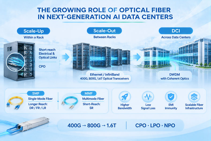
The transition from 100G and 400G optical interfaces to 800G and 1.6T is changing how optical transceivers are designed, qualified, and manufactured. Higher data rates place greater demands on signal integrity, optical performance, electrical interfaces, thermal management, and host compatibility. A module that passes basic optical power measurements may still encounter problems when operating at its intended lane rate or inside a specific network platform.
Modern optical transceiver testing therefore requires a broader validation approach. Manufacturers must evaluate individual optical lanes, transmitter signal quality, receiver sensitivity, bit error rate (BER), forward error correction (FEC), power consumption, management functions, and interoperability. As module architectures become more complex, test coverage must also extend from individual components to complete host-to-host links.
The evolution toward 800G and 1.6T does not simply require faster test equipment. It requires more accurate measurements, higher-bandwidth electrical instrumentation, improved automation, better lane-level traceability, and more comprehensive system validation.
1. Why Optical Transceiver Testing Requirements Are Changing
Higher-speed optical modules introduce tighter electrical and optical operating margins. Increasing aggregate bandwidth usually involves higher per-lane signaling rates, additional parallel channels, more advanced modulation, or a combination of these approaches.
These changes affect both the module and the equipment used to verify it.
Higher lane rates: Faster electrical and optical signals require test instruments with greater bandwidth and more precise signal characterization.
PAM4 signaling: Four-level modulation introduces additional signal-quality considerations compared with traditional NRZ signaling.
More complex DSP and FEC: Digital signal processing and error correction must be evaluated as part of the complete transmission system.
Higher port density: Multi-lane modules require consistent performance across multiple transmit and receive channels.
Increasing power density: Thermal behavior and power consumption become more important as module processing capabilities increase.
More sophisticated management: Modern modules expose additional configuration, monitoring, and diagnostic functions through management interfaces such as CMIS.
Consequently, optical module qualification is moving beyond isolated component measurements toward coordinated electrical, optical, thermal, functional, and system-level testing.
2. The Difference Between Testing 100G, 400G, 800G, and 1.6T Modules
Each generation of optical transceivers introduces different testing priorities. The exact requirements depend on the optical interface, form factor, modulation format, lane architecture, and applicable standard. Nevertheless, several broad changes can be identified across successive generations.
| Data Rate Generation | Common Signaling Characteristics | Major Testing Priorities |
|---|---|---|
| 100G | NRZ or early PAM4 implementations, depending on interface | Optical power, wavelength, receiver sensitivity, BER, electrical compliance |
| 400G | Multi-lane PAM4, including 50G-class and 100G-class lane architectures | Per-lane signal quality, TDECQ, BER, FEC, electrical signal integrity |
| 800G | Commonly 8 × 100G-class or other supported lane configurations | Multi-lane consistency, PAM4 measurements, receiver performance, power, thermal behavior, interoperability |
| 1.6T | Emerging 8 × 200G-class architectures and other implementation-dependent configurations | Higher-bandwidth electrical and optical validation, lane synchronization, FEC, thermal qualification, host compatibility |
The lane configurations above are representative architecture categories rather than universal requirements for every module. Actual test procedures must follow the specific product specification and applicable Ethernet, MSA, or implementation agreement.
For example, a 400G module using eight 50G-class PAM4 lanes and a 400G module using four 100G-class lanes do not necessarily require identical test fixtures or measurement configurations. The same principle applies to 800G and 1.6T products.
3. Transmitter Testing: Signal Quality Becomes More Critical
The transmitter converts electrical input data into an optical signal. Its performance directly affects the quality of the signal entering the fiber channel. As signaling rates increase, transmitter measurements must identify smaller impairments and verify that each lane operates within the applicable limits.
Common transmitter measurements include:
Average optical output power: Verifies that the transmitted optical power falls within the specified operating range.
Optical modulation amplitude (OMA): Measures the optical power difference between signal levels and helps characterize modulation quality.
Wavelength: Confirms that the optical carrier operates within the required wavelength range.
Extinction ratio: Evaluates the optical power relationship between logical signal levels.
Eye diagram: Visualizes signal transitions, noise, timing variation, and the separation between signal levels.
TDECQ: Evaluates transmitter and dispersion penalties for PAM4 signals under a defined reference measurement methodology.
RIN and spectral characteristics: Assess relative intensity noise and other optical properties where required by the relevant interface specification.
For PAM4 transmitters, eye analysis becomes particularly important because information is represented by four optical amplitude levels rather than two. The spacing between adjacent levels is smaller, making the signal more sensitive to noise, distortion, and other impairments.
Testing should examine individual lanes rather than relying only on an aggregate module result. A module can have acceptable overall output power while one lane exhibits weaker signal quality or an abnormal operating characteristic.
4. Understanding TDECQ and PAM4 Eye Diagram Testing
TDECQ, or Transmitter and Dispersion Eye Closure for PAM4, is an important transmitter measurement used in high-speed PAM4 optical interfaces. It provides a standardized way to assess signal degradation associated with transmitter quality and dispersion under a defined reference receiver and measurement procedure.
Unlike a simple optical power measurement, TDECQ evaluates the quality of the transmitted waveform after applying the specified reference equalization methodology.
Eye diagram testing also helps engineers identify:
Insufficient separation between PAM4 signal levels.
Excessive timing jitter and signal distortion.
Uneven eye openings across the three PAM4 eye regions.
Noise and waveform degradation.
Lane-to-lane variations in transmitter performance.
As lane rates increase, the required bandwidth and calibration quality of sampling oscilloscopes, optical reference receivers, and associated measurement equipment become more demanding. Test engineers must also verify that the instrument configuration is appropriate for the specific signaling rate and modulation format.
5. Receiver Testing: Sensitivity, Overload, and BER
Receiver testing verifies that an optical module can recover incoming data under the expected optical and signal conditions. A receiver must operate reliably when the received signal approaches its minimum specified level, but it must also tolerate higher input power within the defined operating range.
Important receiver measurements include:
| Test Parameter | Purpose | Engineering Significance |
|---|---|---|
| Receiver sensitivity | Determines the minimum input signal level for the specified performance | Establishes the lower operating boundary of the receiver |
| Overload | Checks receiver operation at higher optical input power | Verifies tolerance to strong received signals |
| BER | Measures the proportion of incorrectly received bits | Evaluates data recovery performance |
| Stressed receiver sensitivity | Tests receiver performance under defined signal impairments | Provides a more demanding assessment of receiver robustness |
| LOS behavior | Verifies loss-of-signal detection and reporting | Checks receiver status behavior during signal interruption |
| Lane performance | Evaluates individual receive channels | Identifies weak or inconsistent lanes |
Receiver sensitivity is not a universal value across all 400G, 800G, or 1.6T modules. It depends on the optical interface, modulation format, wavelength, receiver architecture, and specified BER or FEC conditions.
For high-speed PAM4 modules, receiver testing should use the appropriate test pattern, reference transmitter or stressed optical signal, and measurement procedure defined by the relevant specification.
6. BER and FEC Testing Become More Closely Connected
Bit Error Rate testing measures the number of incorrectly received bits relative to the total number of transmitted bits. It remains one of the most important indicators of transmission performance.
However, modern high-speed optical modules frequently rely on FEC to correct transmission errors. This means that a complete validation process may need to examine both the error performance before correction and the residual performance after correction.
Several measurements are relevant:
Pre-FEC BER: Measures errors before the FEC decoder corrects them. It provides information about the quality of the incoming signal.
Post-FEC BER: Measures residual errors after FEC processing. It indicates whether the corrected link achieves the required error performance.
FEC correction statistics: Help identify how frequently the decoder is correcting errors and whether the link is approaching its operating margin.
Uncorrectable error events: Reveal cases where the received data cannot be recovered within the capabilities of the selected FEC scheme.
BER stability over time: Helps identify intermittent problems that may not appear during a short functional test.
Pre-FEC and post-FEC results must not be treated as interchangeable. A link can show a measurable pre-FEC error rate while still delivering an acceptable corrected output. Conversely, increasing correction activity may indicate that the optical channel is losing margin.
Testing must therefore use the FEC scheme and performance criteria specified for the particular interface. Different generations and interface types may use different coding structures and thresholds.
7. Electrical Interface Testing at Higher Lane Rates
Optical transceiver validation is not limited to the optical side. The electrical interface between the host equipment and the module is equally important.
In high-speed pluggable modules, electrical signals pass through host connectors, module contacts, PCB traces, and internal signal-conditioning circuits. Losses and reflections across these components can affect signal quality before the data reaches the optical transmitter.
Electrical validation may include:
Insertion loss: Evaluates signal attenuation through the electrical channel.
Return loss: Measures reflected signal energy caused by impedance discontinuities.
Insertion loss deviation: Helps characterize the frequency-dependent behavior of the channel.
Jitter: Measures timing variations that affect signal sampling and recovery.
Eye height and eye width: Evaluate the available electrical signal margin.
Equalization performance: Checks how transmitter and receiver equalization compensate for channel loss and distortion.
Host-module signal integrity: Verifies that the electrical interface operates correctly with the intended host platform.
As electrical lane rates increase, test fixtures and measurement setups become more sensitive to connector quality, cable characteristics, calibration, and de-embedding accuracy. A test fixture that is adequate for an earlier generation may not provide sufficient bandwidth or measurement confidence for a newer interface.
8. Power Consumption and Thermal Testing
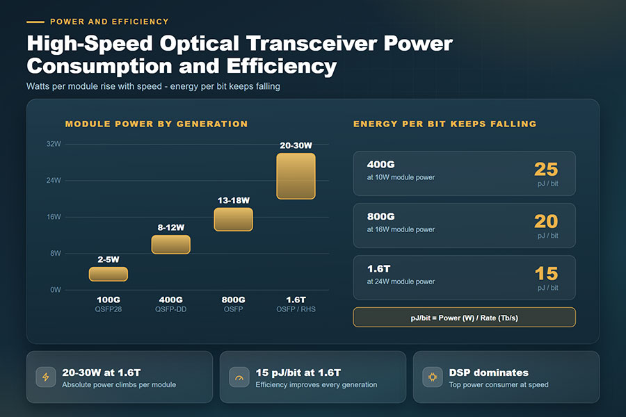
Higher-speed optical transceivers generally integrate more advanced signal-processing and optical components. Depending on the architecture, these may include DSPs, retimers, drivers, laser control circuits, and additional thermal-management features.
Power and thermal testing must establish whether the module can operate reliably within its specified conditions.
Typical checks include:
Module power consumption under defined operating modes.
Power behavior during initialization and normal operation.
Case temperature and internal temperature monitoring where supported.
Optical output stability across the specified temperature range.
Receiver performance under thermal variation.
Thermal behavior during sustained high-bandwidth traffic.
Alarm and warning thresholds reported through the management interface.
Thermal testing becomes especially important for high-density 800G and 1.6T deployments. Multiple high-power modules installed in adjacent switch ports can create local hot spots and affect airflow conditions.
For example, C-LIGHT's 1.6T OSFP-RHS optical transceiver uses a reduced-height heatsink design intended for demanding thermal environments, including systems designed around cold-plate or liquid-cooling integration. Qualification should still be performed in the intended host platform because actual thermal performance depends on the complete system design.
9. CMIS and Digital Diagnostic Testing
Modern optical transceivers provide more than optical signal conversion. Their management interfaces allow host equipment to identify modules, configure operating modes, monitor operating conditions, and retrieve diagnostic information.
CMIS, or Common Management Interface Specification, provides a standardized management framework for supported optical module and cable types. As module architectures become more sophisticated, management-interface validation has become an important part of product qualification.
Testing may cover:
Module identification and supported application advertisement.
Management communication and register access.
Module initialization and state transitions.
Data path activation and deactivation.
Transmit and receive power monitoring.
Temperature and supply-voltage reporting.
Alarm and warning flag behavior.
Module reset and recovery behavior.
Supported firmware and management-function behavior.
Digital diagnostics can help identify abnormal operating conditions that are not immediately visible through basic link status. For example, unusual temperature trends, receive-power fluctuations, or increasing error indicators may help engineers identify a developing problem.
Management testing should use the CMIS revision and form-factor-specific requirements applicable to the module. The Open Compute Project's optics telemetry work also highlights the importance of exposing module and link-partner information to host systems for monitoring and operational analysis.
10. Interoperability Testing Across Switches and Network Platforms
A module may pass optical and electrical laboratory tests but still encounter compatibility issues in a real network device. Host platforms can differ in firmware, module configuration, electrical characteristics, power limits, thermal behavior, and management implementation.
Interoperability testing verifies the complete communication path between the optical transceiver and its intended host equipment.
Important validation items include:
Module recognition and identification.
Correct form-factor and application-code detection.
CMIS communication and supported configuration.
Link establishment and stable operation.
Correct lane mapping and breakout configuration.
Ethernet or InfiniBand protocol compatibility where applicable.
FEC mode and link negotiation behavior.
Traffic throughput and error monitoring under load.
Hot-plug, reset, and restart behavior.
Power and thermal compatibility with the host platform.
Testing with multiple qualified switch, router, and network interface platforms can reveal host-specific issues that are difficult to identify through standalone optical characterization.
11. Production Testing and Quality Control
Development qualification and production screening serve different purposes. Engineering qualification establishes whether a design meets its technical requirements across defined operating conditions. Production testing checks whether each manufactured unit meets the required acceptance criteria consistently.
As module data rates increase, manufacturers need efficient production test systems that maintain measurement accuracy without creating excessive test time.
| Production Test | Primary Purpose | Typical Test Coverage |
|---|---|---|
| Module identification | Verify product identity and management information | EEPROM, module type, revision and supported modes |
| Optical power | Screen transmitter output | Average power and lane-level output |
| Wavelength | Verify optical carrier characteristics | Center wavelength and applicable spectral limits |
| Eye and TDECQ | Evaluate high-speed transmitter signal quality | Applicable PAM4 eye and transmitter measurements |
| BER or functional test | Verify transmission and reception | Lane operation, error performance and link functionality |
| Power consumption | Check electrical operating behavior | Power draw under defined operating conditions |
| Thermal screening | Identify abnormal temperature behavior | Temperature monitoring and selected operating tests |
| Host compatibility | Verify target platform operation | Recognition, initialization and link establishment |
Not every engineering measurement needs to be repeated with identical depth on every production unit. A well-designed production plan separates full design qualification, routine manufacturing screening, and periodic reliability verification.
Automated test systems should record serial numbers, test conditions, instrument configurations, lane-level measurements, pass/fail results, and calibration status. This traceability helps manufacturers identify process variation and investigate field issues.
12. Reliability Testing Beyond Basic Functional Performance
Passing an optical or electrical test at room temperature does not establish long-term reliability. Optical modules must also be evaluated under environmental and operating conditions relevant to their intended applications.
Depending on the product category and qualification plan, reliability testing may include:
Temperature cycling: Evaluates performance after repeated changes between specified temperature conditions.
High-temperature operation: Assesses behavior during sustained operation at elevated temperatures.
Humidity exposure: Evaluates environmental durability under specified humidity conditions.
Mechanical shock and vibration: Checks resistance to mechanical stresses relevant to the installation environment.
Connector durability: Evaluates the mechanical performance of optical and electrical interfaces under defined mating conditions.
Long-duration operation: Monitors performance stability over extended operating periods.
ESD and electrical protection: Evaluates compliance with applicable electrostatic and electrical handling requirements.
Reliability testing should be based on the product's intended environment, applicable industry standards, customer requirements, and qualification plan. A data center optical module and an industrial-temperature transceiver may require different environmental test profiles.
13. Test Equipment Requirements for 800G and 1.6T
Higher data rates place increasing demands on optical and electrical test instruments. A test system must be capable of generating, capturing, and analyzing signals at the required lane rate while maintaining sufficient measurement accuracy.
| Test Equipment | Application | Higher-Speed Testing Requirement |
|---|---|---|
| High-bandwidth sampling oscilloscope | Electrical and optical waveform analysis | Bandwidth and sampling performance appropriate for the lane rate |
| Optical reference receiver | Transmitter signal characterization | Correct optical bandwidth and reference response |
| Bit error rate tester | BER and receiver performance testing | Required line rate, pattern support, and lane configuration |
| Optical power meter | Transmitter output and receiver input measurements | Suitable wavelength range, accuracy, and dynamic range |
| Optical spectrum analyzer | Wavelength and spectral analysis | Resolution and measurement range appropriate for the optical interface |
| Variable optical attenuator | Receiver sensitivity and overload testing | Controlled attenuation with suitable accuracy and stability |
| High-speed pattern generator | Electrical stimulus and transmitter testing | Required signaling rate, pattern, and interface support |
| Thermal chamber | Temperature-dependent qualification | Controlled environmental conditions and suitable monitoring |
| Automated test platform | Production screening and traceability | Multi-lane coverage, repeatability, and data management |
Instrument bandwidth alone does not guarantee accurate measurements. Calibration, reference fixtures, optical connectors, test fibers, signal conditioning, and measurement uncertainty must also be controlled.
For multi-lane modules, the test architecture should provide sufficient channel capacity and repeatable switching or connection arrangements. Otherwise, test time and setup variation can become significant manufacturing constraints.
14. Standards and Industry Specifications Shape Test Procedures
Optical transceiver testing should be based on the applicable interface standards and implementation agreements rather than a single universal checklist. Different optical PMDs, electrical interfaces, form factors, and coherent modules can have different requirements.
Several standards organizations and industry groups contribute to the technical framework:
IEEE 802.3: Defines Ethernet physical-layer specifications and associated optical and electrical measurement requirements for supported interfaces.
OIF: Develops implementation agreements for electrical, optical, coherent, and management interfaces.
QSFP-DD MSA: Defines mechanical, electrical, and management-related requirements for QSFP-DD form factors.
OSFP MSA: Defines form-factor and interface requirements for OSFP modules.
IEC: Publishes measurement and testing standards relevant to fiber-optic components and systems.
IEEE 802.3df-2024 addresses 400 Gb/s and 800 Gb/s Ethernet physical layers and related management parameters. For newer 1.6T-class interfaces, engineers should check the latest applicable standardization documents and implementation agreements rather than assuming that existing 800G limits or test procedures can be reused unchanged.
Management testing also needs to track specification revisions. OIF published CMIS Revision 5.4 in May 2026, with further management-related implementation work continuing during 2026. Module qualification should identify the exact revision implemented by the product and the requirements supported by the host.
15. How C-LIGHT Applies Testing to Higher-Speed Optical Modules
As optical interfaces move toward 800G and 1.6T, product qualification and manufacturing consistency become increasingly important. C-LIGHT's high-speed optical transceiver portfolio covers multiple form factors and transmission distances for data center, cloud computing, and AI networking applications.
Relevant product families include:
400G OSFP optical transceivers: The C-LIGHT 400G OSFP series supports up to 400Gb/s and lists IEEE 802.3/cu/ck, InfiniBand NDR, CMIS Rev. 5.2, and OSFP MSA HW compatibility in its product description.
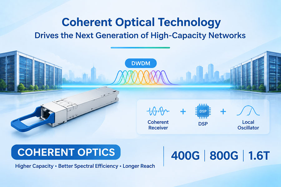
400G QSFP-DD optical transceivers: The 400G QSFP-DD series includes direct-detect and coherent configurations for different data center and optical transport applications.
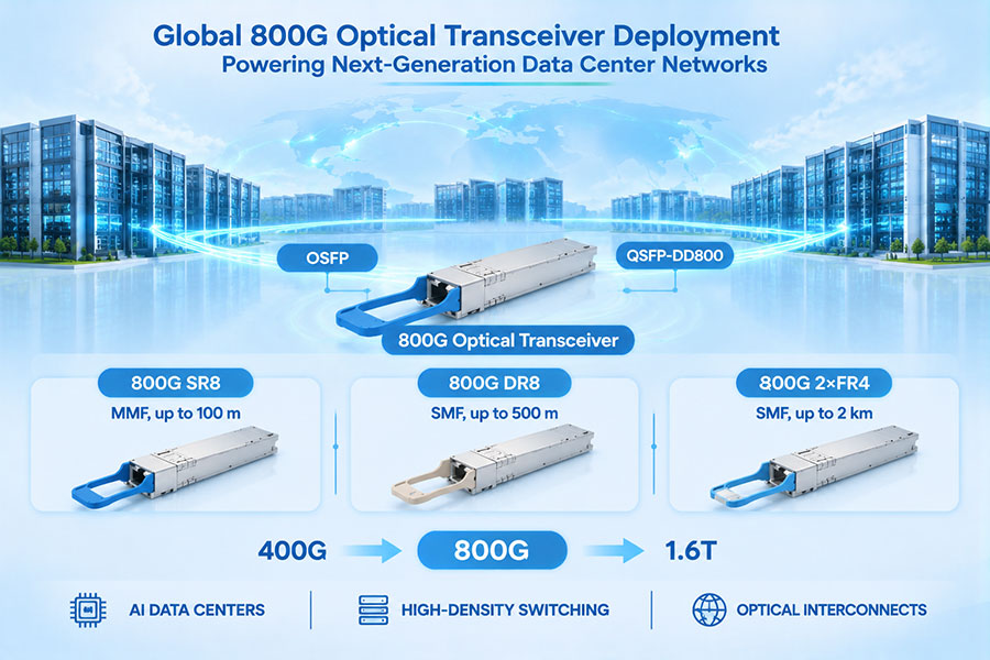
800G OSFP optical transceivers: The 800G OSFP series covers VR8, SR8, DR8, and 2×FR4 configurations, with the published product information listing CMIS Rev. 5.0 and OSFP MSA HW support.
800G QSFP-DD optical transceivers: The 800G QSFP-DD series provides additional form-factor options for high-density network deployments.
1.6T OSFP-RHS optical transceivers: The 1.6T OSFP-RHS series uses an 8 × 200G PAM4 architecture with integrated DSP and FEC, targeting next-generation AI and hyperscale data center networks.
C-LIGHT's product pages describe a 100% testing commitment for its listed optical module products. For specific projects, customers should confirm the applicable test coverage, acceptance criteria, qualification records, and platform compatibility requirements for the selected model.
For high-speed optical module procurement, a clear testing specification helps align the supplier's quality-control process with the customer's network requirements. It should identify the required interface, operating conditions, test parameters, host platform, and acceptance criteria before production qualification begins.
16. Conclusion: Testing Must Advance Alongside Optical Data Rates
The transition to 400G, 800G, and 1.6T optical interfaces is making transceiver testing more demanding. Higher lane rates, PAM4 signaling, advanced DSP and FEC, increasing module power, and more complex management functions require a broader approach to product validation.
Reliable testing now involves more than checking optical output power or confirming that a module establishes a link. Transmitter and receiver characterization, BER and FEC analysis, electrical signal integrity, thermal performance, CMIS management, interoperability, and production traceability all contribute to product quality.
As the industry moves toward higher-capacity optical networks, manufacturers and network operators must update their test equipment, measurement methods, and qualification procedures accordingly. A consistent, standards-based testing strategy helps identify marginal performance, improve manufacturing repeatability, and reduce compatibility risks in high-speed data center infrastructure.
Looking for high-speed optical transceivers with defined testing and compatibility requirements?
C-LIGHT provides optical transceiver solutions across 400G, 800G, and 1.6T product families. Contact our team to discuss product specifications, qualification requirements, and network compatibility.
 >

 >
 >
 >
 >
 >
 >
 >