TEL:+86 132 6656 7067





Next-generation data center networks are facing a fundamental interconnect challenge. As AI accelerators, high-performance computing systems, and distributed workloads generate increasingly intensive communication traffic, conventional electrical packet-switching architectures must handle growing bandwidth requirements while controlling power consumption, congestion, and network complexity.
Optical Circuit Switching (OCS) is gaining attention as an alternative way to organize high-capacity network connectivity. Rather than processing individual packets at every switching stage, an OCS fabric establishes configurable optical paths between selected endpoints. Once a circuit is configured, optical signals can pass through the switching fabric without repeated optical-electrical-optical conversion inside the OCS device.
This architecture creates new possibilities for AI cluster networking, data center interconnection, and scalable optical infrastructure. Advances in MEMS, liquid-crystal devices, silicon photonics, and automated network control are expanding the range of optical switching designs. At the same time, 800G and 1.6T optical interfaces are increasing the bandwidth available at the endpoints of these reconfigurable networks.
1. Why Optical Circuit Switching Is Gaining Industry Attention
Traditional data center networks rely heavily on electrical packet switches. These devices receive packets, inspect forwarding information, select output ports, and manage traffic through switching fabrics and buffers. This architecture provides flexible packet-level connectivity and remains essential for general-purpose data center networking.
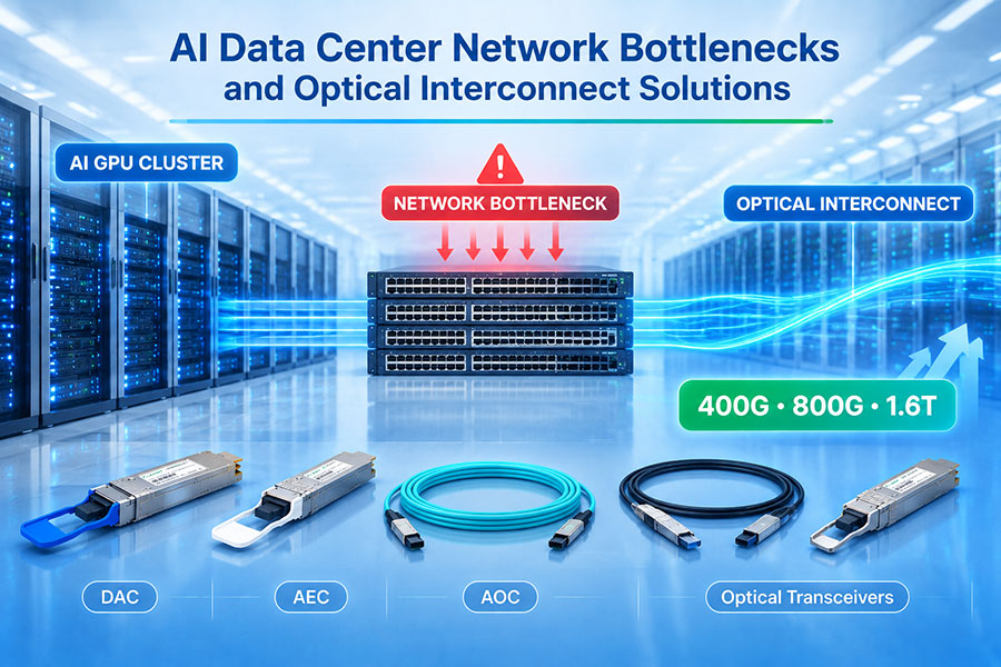
However, the expansion of large AI clusters is creating communication patterns that can place considerable pressure on conventional network fabrics. Distributed training, collective communication, and accelerator synchronization require large amounts of data to move between groups of computing nodes.
As network bandwidth increases, the power and complexity associated with electrical switching also become important design considerations. OCS offers another approach by creating direct optical connections for traffic flows that can benefit from dedicated high-capacity paths.
Several factors are driving interest in OCS:
AI cluster expansion: Large accelerator clusters require high-bandwidth communication between computing groups.
Network power consumption: Optical circuit switching can reduce some of the power overhead associated with repeated electronic packet processing.
High-capacity interconnection: Optical paths can carry high-rate signals without packet-by-packet processing inside the OCS fabric.
Dynamic network topology: Reconfigurable optical connections allow network operators to adjust physical connectivity as workload requirements change.
Scalable optical infrastructure: OCS can provide an additional switching layer within hybrid electrical and optical network architectures.
The Open Compute Project established an OCS subproject to advance open specifications, software integration, telemetry, and interoperability. Its April 2026 technical white paper also reviews the major OCS technologies and their application in AI and hyperscale data center networks.
2. What Is Optical Circuit Switching?
Optical Circuit Switching is a network switching method that establishes a physical optical path between an input port and an output port. The connection is configured before the associated traffic is transmitted and remains in place until the network controller changes or releases the circuit.
Unlike an electrical packet switch, an OCS device generally does not need to decode packet headers or perform packet forwarding decisions for each data unit. Its primary function is to direct incoming optical signals toward selected output fibers.
A typical OCS connection involves three stages:
Circuit configuration: A network controller determines the required connection and instructs the optical switch to establish the path.
Optical signal transmission: The source transceiver sends optical signals through the configured path to the destination.
Circuit reconfiguration or release: When the communication requirement changes, the controller can modify the optical connection or allocate the path to another endpoint.
Because the OCS fabric can operate transparently to the signal's data format, the optical path may carry different supported protocols and line rates without requiring the switch itself to interpret their packet structures. Actual compatibility still depends on the optical interfaces, signal characteristics, wavelength plan, and system design.
3. How an OCS Network Architecture Works
An OCS-based network typically combines optical circuit switches, endpoint transceivers, fiber connections, electrical packet switches, and a centralized or distributed control system.
At the network edge, servers, GPUs, or electrical switches connect to optical transceivers. These transceivers convert electrical data into optical signals and transmit them through fiber links toward the OCS fabric.
The OCS establishes the required physical connection between selected input and output ports. The receiving endpoint then converts the optical signal back into an electrical signal for processing by the connected device.
A simplified architecture contains the following components:
| Component | Primary Function | Network Position |
|---|---|---|
| GPU or compute server | Generates and processes application data | Network endpoint |
| Optical transceiver | Converts electrical and optical signals | Endpoint interface |
| Optical fiber link | Carries optical signals between devices | Physical transmission layer |
| Optical circuit switch | Establishes configurable optical paths | Optical switching fabric |
| Electrical packet switch | Provides packet-level forwarding and traffic management | Electrical network layer |
| Network controller | Coordinates circuit allocation and topology changes | Control plane |
| Monitoring system | Tracks link quality, optical power, and operational status | Management plane |
The exact topology depends on the deployment. Some architectures use OCS to replace selected electrical spine-layer connections, while others introduce optical switching between groups of compute racks or accelerator clusters.
4. OCS vs. Electrical Packet Switching
OCS and electrical packet switching solve different networking problems. Electrical packet switches provide flexible, fine-grained forwarding, while optical circuit switches establish dedicated physical paths for traffic that can benefit from sustained bandwidth and predictable optical connectivity.
| Technical Factor | Optical Circuit Switching | Electrical Packet Switching |
|---|---|---|
| Switching method | Configures physical optical paths | Forwards individual packets |
| Traffic processing | Does not require packet-header processing inside the optical fabric | Uses packet parsing and forwarding logic |
| Buffering | No packet buffering in a transparent optical path | Uses buffers to manage packet traffic and congestion |
| Latency characteristics | Very low switching-path latency after circuit establishment | Includes electronic forwarding and queueing delays |
| Reconfiguration | Requires circuit setup and switching time | Supports packet-level forwarding decisions |
| Traffic flexibility | Best suited to traffic patterns that can use configured circuits | Highly flexible for variable and bursty traffic |
| Protocol transparency | Can carry supported optical signals without packet interpretation | Processes traffic according to supported network protocols |
| Typical application | High-bandwidth cluster and optical fabric connections | General-purpose data center networking |
OCS can reduce switching-path latency and avoid packet buffering within the optical fabric. However, circuit establishment takes time, and the end-to-end network still includes endpoint processing, transceiver conversion, fiber propagation, and potentially electrical switching elsewhere.
For this reason, OCS is not a universal replacement for electrical packet switches. A hybrid architecture can use electrical switching for flexible packet delivery and OCS for selected high-bandwidth connections.
5. Major OCS Switching Technologies
Optical circuit switches can be implemented using several physical mechanisms. Each technology has different characteristics in terms of port count, insertion loss, switching speed, optical stability, mechanical complexity, and scalability.
The Open Compute Project's 2026 OCS white paper identifies several major technology categories.
MEMS-based optical switching
Micro-Electro-Mechanical Systems use miniature movable structures, such as micro-mirrors, to redirect optical beams between input and output ports. MEMS technology is widely associated with high-port-count optical switching because it can create configurable free-space optical paths.
MEMS-based systems can support large switching fabrics, but their design must account for optical alignment, mechanical stability, environmental conditions, and switching time.
Liquid-crystal optical switching
Liquid-crystal technologies use electrically controlled changes in optical properties to influence the direction or routing of light. Depending on the implementation, they can provide flexible optical switching without relying on conventional mechanical mirror movement.
Performance depends on the optical design, device architecture, polarization management, and required switching characteristics.
Silicon photonics switching
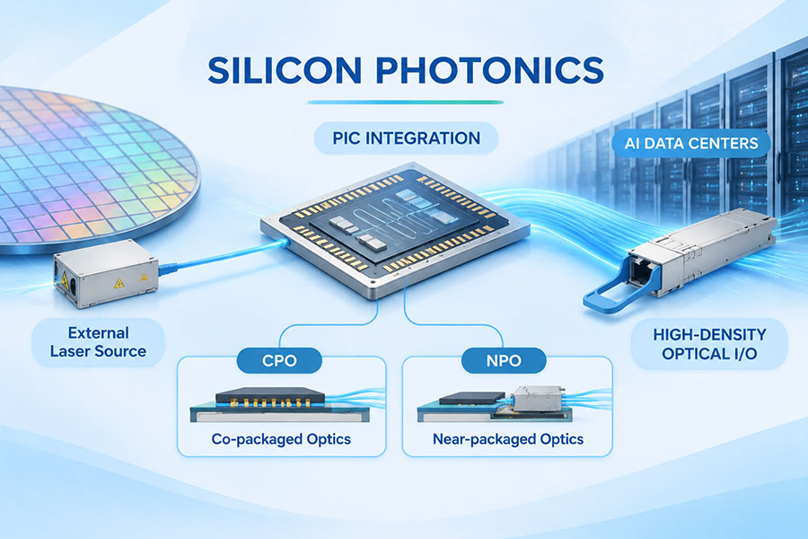
Silicon photonics integrates optical functions onto semiconductor-based photonic chips. Waveguides, couplers, and tunable optical elements can be combined to create compact switching structures.
This approach offers opportunities for integration and manufacturing scalability, although insertion loss, thermal sensitivity, optical crosstalk, and port-count scaling remain important engineering considerations.
Robotic and piezo-actuated switching
Some OCS designs use robotic mechanisms or piezoelectric actuators to move optical components and establish physical connections. These approaches can provide configurable routing, but their mechanical structure, reliability, and switching behavior must be evaluated against the target deployment.
| Technology | Switching Mechanism | Key Design Considerations |
|---|---|---|
| MEMS | Movable micro-mirrors or mechanical structures | Port count, alignment, insertion loss, mechanical stability |
| Liquid crystal | Electrically controlled optical properties | Polarization, switching time, optical efficiency |
| Silicon photonics | Integrated waveguides and tunable photonic elements | Integration density, crosstalk, thermal control, optical loss |
| Robotic switching | Mechanically positioned optical components | Mechanical complexity, reliability, reconfiguration time |
| Piezo-actuated switching | Precision movement through piezoelectric actuation | Positioning accuracy, stability, device complexity |
No single switching mechanism is ideal for every network. Selection depends on the required number of ports, optical loss budget, switching frequency, operational environment, and cost targets.
6. MEMS OCS and High-Port-Count Optical Fabrics
High-port-count switching is important for large AI clusters because the network may need to connect many groups of compute nodes through a configurable optical fabric.
MEMS-based OCS designs are particularly relevant to this requirement. By using movable micro-mirrors to redirect optical signals, a MEMS fabric can establish connections between different input and output ports without performing packet-level processing.
For a high-port-count OCS system, several parameters require attention:
Port count: The number of optical inputs and outputs that can be connected through the switching fabric.
Insertion loss: Optical power lost as the signal passes through the switch.
Switching time: The time required to establish or change an optical connection.
Repeatability: The consistency of optical routing across repeated switching operations.
Optical isolation: The ability to limit unwanted signal leakage between different paths.
Mechanical reliability: The stability of movable components over the expected operating lifetime.
High port count alone does not determine whether an OCS is suitable for a particular data center. The switch must also meet the optical loss budget, endpoint interface requirements, and network reconfiguration targets.
7. OCS and AI Cluster Networking
AI training workloads require frequent communication between accelerators. Depending on the training architecture, GPUs may exchange gradients, synchronize model parameters, or transfer intermediate data through collective communication operations.
As clusters become larger, communication performance can influence overall training efficiency. Network congestion, oversubscription, and inconsistent communication paths may limit the utilization of expensive computing resources.
OCS offers a way to adjust the physical network topology according to selected workload requirements. Instead of relying exclusively on a fixed electrical switching structure, network operators can establish optical paths between groups of compute resources.
Potential applications include:
AI cluster interconnection: Connecting accelerator groups through high-capacity optical paths.
Training-stage reconfiguration: Adjusting network connectivity as communication requirements change between workload stages.
Collective communication: Providing dedicated paths for traffic patterns that benefit from sustained bandwidth.
GPU resource allocation: Supporting flexible connectivity between compute groups in disaggregated infrastructure.
MoE workloads: Providing configurable communication paths for distributed expert and accelerator groups.
However, the benefits depend on how well circuit allocation matches actual workload behavior. If traffic changes more frequently than the OCS can reconfigure, the setup overhead may reduce the expected gains. Workload-aware scheduling is therefore an important part of an effective OCS deployment.
8. OCS in Scale-Out and Scale-Up Network Architectures
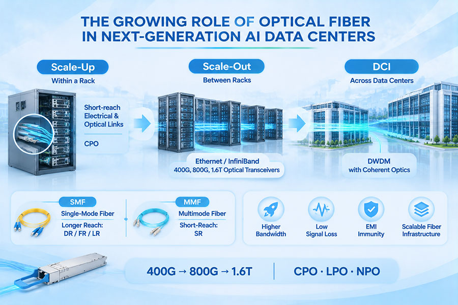
Modern AI data centers use different network domains to connect processors, servers, racks, and clusters. Scale-up networks connect processors or accelerators within tightly coupled systems, while scale-out networks connect servers and racks across a larger data center fabric.
OCS is being considered in both domains, although the design requirements differ.
Scale-out networking
Scale-out architectures connect large numbers of servers and accelerator systems. OCS can be deployed within selected switching layers to create configurable optical paths between racks or compute groups.
One deployment model uses OCS as an alternative to some electrical spine-layer connections. In this arrangement, electrical packet switches continue to provide the required packet-level connectivity, while the OCS fabric establishes high-capacity paths for suitable traffic groups.
Scale-up networking
Scale-up architectures focus on high-bandwidth communication between closely connected accelerators. OCS and other optical interconnect technologies are being investigated as ways to extend optical connectivity across larger compute domains.
However, scale-up networks have demanding requirements for bandwidth, latency, synchronization, and topology. OCS suitability depends on the workload, endpoint architecture, switching technology, and reconfiguration requirements.
Scale-across networking
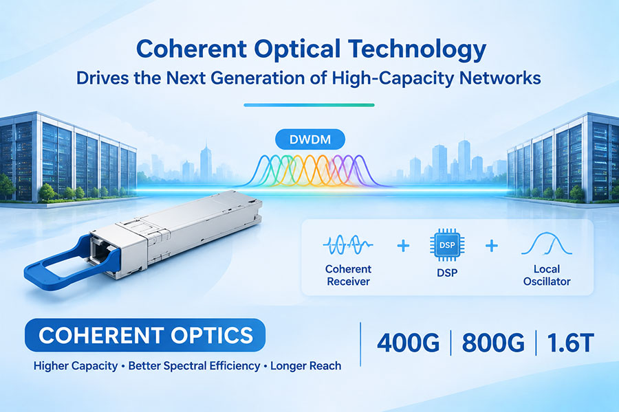
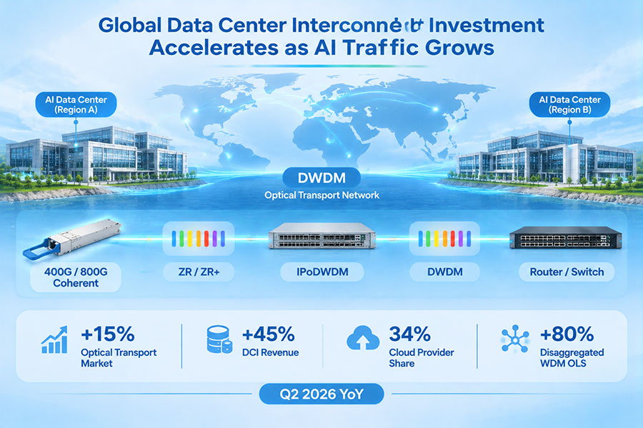
Scale-across architectures connect geographically distributed data centers or large compute facilities. Optical transport systems, coherent interfaces, and reconfigurable wavelength networks can support these links. OCS may provide circuit-level connectivity within selected optical network domains, while long-distance transport requires additional optical transmission engineering.
9. OCS and 800G Optical Interconnects
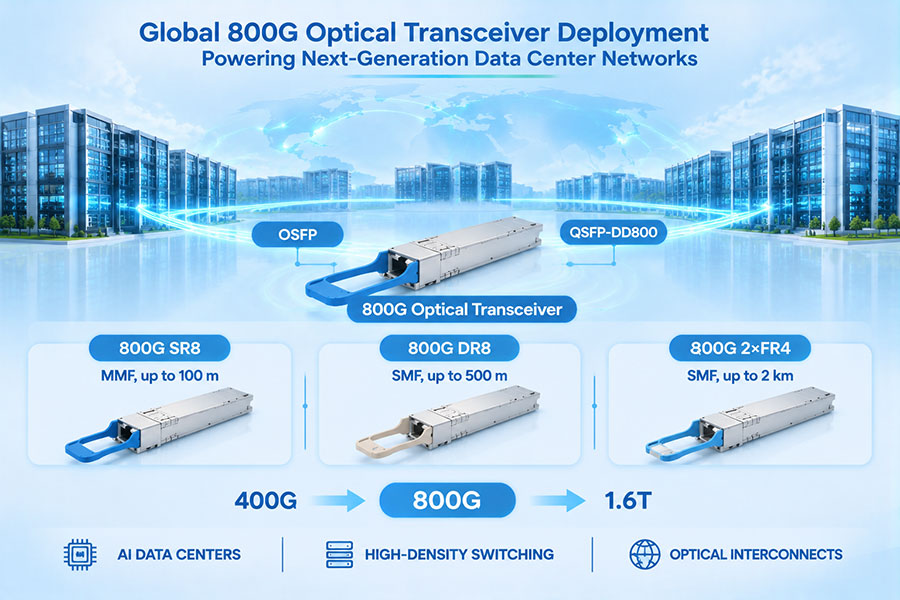
The transition toward 800G optical interfaces is increasing the bandwidth available between servers, switches, and optical switching fabrics. An OCS system can provide the intermediate optical path, while 800G transceivers at the endpoints convert electrical data into optical signals and back.
Common 800G form factors include OSFP and QSFP-DD. The appropriate choice depends on the host platform, optical reach, connector arrangement, power requirements, and OCS architecture.
Different optical configurations support different link requirements:
| 800G Configuration | Typical Application | Important Considerations |
|---|---|---|
| 800G SR8 | Short-reach multimode fiber connections | Fiber type, connector, link loss, and reach |
| 800G DR8 | Single-mode fiber connections for data center links | Parallel optical lanes and MPO connectivity |
| 800G 2×FR4 | Single-mode links using two optical channels groups | Dual optical interfaces and wavelength configuration |
| 800G VR8 | Very short-reach multimode connections | Host platform and multimode fiber compatibility |
For an OCS deployment, transceiver selection must consider more than the data rate. The switch's optical path must be compatible with the transceiver wavelength range, fiber type, connector, polarization characteristics where relevant, and total insertion-loss budget.
10. 1.6T Optical Interfaces and Future OCS Fabrics
As AI accelerator bandwidth continues to increase, 1.6T optical interfaces are emerging as another important development in data center connectivity. Higher-rate transceivers can provide greater bandwidth per endpoint, helping reduce the number of physical connections required for a given aggregate traffic capacity.
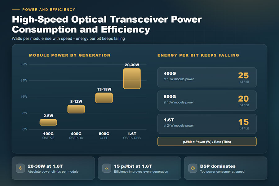
However, increasing endpoint speed also places greater demands on the optical switching fabric. Connector performance, fiber routing, insertion loss, thermal management, and host electrical interfaces all become important considerations.
For 1.6T OCS-related architectures, system designers need to evaluate:
Compatibility between the 1.6T transceiver and the host platform.
Optical lane configuration and supported modulation format.
Fiber type, connector arrangement, and optical link budget.
OCS insertion loss and available receiver power margin.
Thermal and power requirements of the endpoint modules.
Control-plane coordination during circuit establishment and reconfiguration.
Higher optical interface speeds do not automatically increase the capacity of an OCS fabric. The total system must support the required number of connections, optical performance, and traffic scheduling behavior.
11. OCS, CPO, and NPO in Next-Generation Optical Interconnects
OCS, Co-Packaged Optics (CPO), and Near-Packaged Optics (NPO) are all part of the broader development of optical connectivity, but they address different architectural challenges.
OCS changes how optical paths are connected across a network. CPO and NPO focus on the placement and integration of optical engines around high-performance switching silicon.
| Technology | Main Function | Architectural Position |
|---|---|---|
| OCS | Establishes configurable optical circuits between ports | Optical switching fabric |
| CPO | Places optical engines within a closely integrated switch package | Switch ASIC and optical interface |
| NPO | Positions optical engines close to the switch ASIC | Near-package optical interface |
| Pluggable optics | Provides replaceable electrical-to-optical interfaces | Equipment front panel or optical port |
These technologies can coexist in the same network. For example, a CPO-based switch may connect to an OCS fabric through suitable optical interfaces, while pluggable transceivers provide optical connectivity at other endpoints.
The correct architecture depends on bandwidth density, optical reach, maintenance requirements, switching topology, and system-level power constraints. OCS does not replace the optical engines or transceivers needed to transmit and receive data.
12. Optical Loss Budget and Signal Integrity in OCS Networks
Optical loss is one of the most important engineering factors in OCS-based networks. Every fiber connection, connector pair, patch panel, and switching element can contribute to the total insertion loss between the transmitting and receiving transceivers.
If the total loss exceeds the optical interface's supported budget, the receiver may not receive sufficient optical power for reliable operation.
The link budget should account for:
Transceiver launch power: The optical power delivered by the transmitting module.
Fiber attenuation: Signal loss along the fiber route.
Connector loss: Loss introduced by fiber connectors and mating interfaces.
OCS insertion loss: Optical power reduction through the switching fabric.
Patch panel and splice loss: Additional losses from intermediate fiber connections.
Engineering margin: Allowance for component variation, aging, and operational conditions.
Optical path quality also depends on return loss, reflectance, crosstalk, polarization-related effects, and the optical characteristics of the selected switching technology.
These parameters should be measured and verified across the complete optical path rather than evaluated from the transceiver specifications alone.
13. OCS Network Control, SDN, and Dynamic Reconfiguration
An OCS fabric requires a control system to determine which optical connections should be established and when they should be changed. Software-Defined Networking provides a framework for coordinating network resources through centralized or logically centralized control.
In an OCS-based architecture, the controller may collect workload information, endpoint status, link availability, and network utilization before allocating optical circuits.
Important control functions include:
Topology management: Maintaining an accurate view of available optical connections.
Circuit allocation: Assigning optical paths to selected endpoints or traffic groups.
Resource scheduling: Coordinating optical connections with application and workload requirements.
Reconfiguration management: Changing circuit assignments when traffic patterns or network conditions change.
Fault handling: Identifying failed paths and coordinating alternative connectivity.
Telemetry integration: Collecting optical power, link status, and operational measurements.
Dynamic reconfiguration is particularly valuable when traffic patterns are predictable enough to schedule optical circuits efficiently. However, circuit setup and teardown introduce control overhead. A network controller must balance the expected bandwidth benefit against the time and resources required to reconfigure the fabric.
14. Operational Challenges in Large-Scale OCS Deployment
Although OCS offers potential benefits in power efficiency and optical connectivity, deploying a large switching fabric introduces operational requirements that differ from conventional packet-switched networks.
One important challenge is that an OCS does not inherently provide packet-based topology discovery. An electrical packet network can use protocols such as LLDP to identify neighboring devices, while an optical circuit switch simply directs light between ports.
As a result, operators need additional procedures to verify fiber connections and optical link quality before services are activated.
Important operational requirements include:
Fiber mapping: Confirming that each physical fiber is connected to the intended input and output ports.
Optical power measurement: Verifying that received power remains within the transceiver's operating range.
Link-loss verification: Measuring the combined insertion loss of the fiber and OCS path.
Connector inspection: Ensuring that fiber end faces are clean and properly connected.
Topology validation: Checking that the configured optical path matches the intended network design.
Fault localization: Identifying whether a problem originates in the fiber route, connector, transceiver, or switching fabric.
These requirements become more significant as the number of optical ports and physical fiber connections increases. Automated optical probing, power measurement, and network inventory systems can help improve deployment efficiency and operational reliability.
15. C-LIGHT Optical Transceivers for OCS-Connected Network Infrastructure
OCS is the switching layer that establishes optical paths between network endpoints. The transceivers connected to those endpoints remain responsible for converting electrical data into optical signals and ensuring that the signal characteristics match the fiber route and switching system.
C-LIGHT provides high-speed optical transceivers and interconnect products for data center and optical transport applications. These products can be considered for compatible endpoint connections in OCS-related network architectures, subject to host-platform and optical-path verification.
C-LIGHT's 1.6T OSFP-RHS product family includes 2×DR4 and 2×FR4 configurations. The listed designs support 2×800G optical channels, 8×200G PAM4 lanes, and integrated DSP/FEC functionality.
The 2×DR4 configuration is specified for single-mode fiber applications up to 500m, while the 2×FR4 configuration supports applications up to 2km. The appropriate model depends on the endpoint interface, fiber infrastructure, and optical link requirements.
These modules are relevant to next-generation high-bandwidth optical endpoint connections. Their use with an OCS fabric requires verification of connector configuration, optical loss, host compatibility, and supported signal characteristics.
Product details: C-LIGHT 1.6T OSFP-RHS Optical Transceivers
C-LIGHT's 800G OSFP portfolio includes SR8, DR8, 2×FR4, and selected coherent configurations. The product family covers different data center and optical transport applications, with reach depending on the specific model.
For OCS-connected networks, the selected optical interface must match the switching fabric's supported optical path, fiber type, connector arrangement, and link-loss budget.
Product details: C-LIGHT 800G OSFP Optical Transceivers
C-LIGHT's 800G QSFP-DD product family includes short-reach and single-mode optical configurations. These modules provide high-speed endpoint connectivity for compatible data center and high-performance networking platforms.
QSFP-DD form factors may be suitable for selected OCS-connected network designs when the host equipment, optical interface, and switching fabric support the required configuration.
Product details: C-LIGHT 800G QSFP-DD Optical Transceivers
C-LIGHT's 400G QSFP-DD portfolio includes SR8, DR4, FR4, LR4, ER4, ZR, ZR+, and selected coherent DCO configurations. The range supports different optical reach and transmission requirements across data center and optical transport environments.
For OCS-related applications, module selection should be based on the actual optical switching path, transmission distance, supported wavelength, and total link budget.
Product details: C-LIGHT 400G QSFP-DD Optical Transceivers
C-LIGHT's optical transceivers provide endpoint connectivity options for compatible high-speed network equipment. They should not be confused with OCS hardware itself: an optical transceiver performs signal conversion, while an OCS establishes the optical path between connected ports.
16. The Future of Optical Circuit Switching
OCS development is moving beyond experimental optical switching concepts toward more integrated network architectures. As AI data centers become larger and more distributed, operators are evaluating ways to combine optical circuit switching, electrical packet switching, advanced transceivers, and software-defined network control.
Several developments are likely to influence future OCS deployments:
Higher-port-count switching: Increasing the number of endpoints supported by a single optical switching fabric.
Lower insertion loss: Improving the optical power margin available for high-speed endpoint connections.
Faster reconfiguration: Reducing the overhead associated with changing optical paths.
Integrated photonic switching: Advancing compact switching structures based on silicon photonics and other integrated optical technologies.
AI-aware scheduling: Coordinating optical circuit allocation with distributed training and inference workloads.
Open hardware and software interfaces: Improving interoperability between OCS devices, network controllers, and monitoring platforms.
Automated optical monitoring: Improving fiber verification, fault detection, and operational visibility.
Hybrid network architectures: Combining optical circuits with packet switching to support different traffic patterns efficiently.
The Open Compute Project's OCS initiative is an important part of this development. Open specifications and shared software interfaces can help reduce integration complexity and improve interoperability across different equipment and network control platforms.
Wider adoption will still depend on measurable improvements in total system cost, reliability, network utilization, optical performance, and operational complexity.
17. Conclusion
Optical Circuit Switching is becoming an important technology direction for next-generation optical interconnects. By establishing configurable optical paths instead of processing every packet within the switching fabric, OCS can provide high-capacity connectivity with low switching-path latency and reduced packet-processing overhead.
MEMS, liquid-crystal, silicon photonics, and other switching technologies offer different approaches to building scalable optical fabrics. Their practical value depends on port count, insertion loss, switching time, reliability, and integration with the wider network architecture.
OCS is not a universal replacement for electrical packet switching. Its strongest role is likely to be within hybrid architectures that combine flexible packet forwarding with configurable optical circuits for selected high-bandwidth traffic patterns.
As 800G and 1.6T optical interfaces become more widely adopted, endpoint transceivers, fiber infrastructure, optical switching fabrics, and software-defined control systems will need to develop together. This coordinated evolution will shape the next generation of scalable, high-performance data center interconnects.
C-LIGHT provides 400G, 800G, and 1.6T optical transceivers, coherent DCO modules, and high-speed connectivity products for compatible data center and optical transport applications. Contact our team for product specifications, host-platform compatibility verification, and optical connectivity support.
 >

 >
 >
 >
 >
 >
 >
 >