TEL:+86 132 6656 7067





The transition toward 800G, 1.6T, and higher-capacity data center networks is placing increasing pressure on the electrical interfaces that connect switching silicon to optical transceivers. As signal rates rise, electrical traces between switch ASICs and front-panel optical modules become more difficult to manage. Signal loss, equalization requirements, power consumption, and board-level routing constraints can limit the bandwidth density of conventional network platforms.
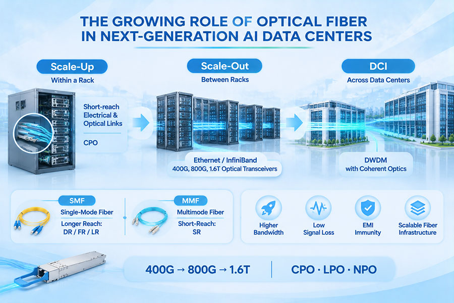
Co-Packaged Optics (CPO) addresses this challenge by bringing optical engines closer to switching or computing silicon within a tightly integrated package architecture. Instead of routing high-speed electrical signals over relatively long board-level connections to removable optical modules, CPO converts electrical signals into optical signals near the processing chip. This approach changes how electrical and photonic components are designed, packaged, cooled, tested, and maintained.
The development of CPO is also accelerating innovation across silicon photonics, electronic-photonic integration, optical coupling, external laser sources, advanced packaging, and automated optical-electrical testing. These technologies are becoming increasingly important as AI infrastructure requires higher bandwidth density and more efficient data movement.
1. Why Optical and Electrical Integration Is Changing
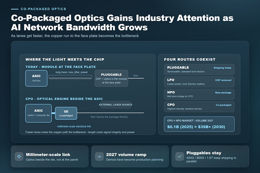
Traditional data center switches use pluggable optical transceivers installed in front-panel cages. The switch ASIC processes network traffic and sends high-speed electrical signals through the package, printed circuit board, and connector to the optical module. The module then converts electrical signals into optical signals for transmission through fiber.
This architecture offers practical advantages, including replaceable modules, established interoperability practices, and relatively straightforward maintenance. However, increasing data rates place greater demands on the electrical channel between the ASIC and the optical interface.
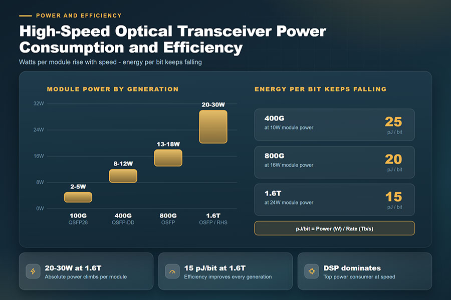
At higher signaling speeds, electrical channel loss and signal distortion become more difficult to compensate for. Retimers, equalization circuits, and other signal-conditioning techniques may increase system power consumption and design complexity. The front-panel area and available electrical routing also become constraints as switch bandwidth increases.
CPO changes the physical relationship between the switching ASIC and the optical interface. By positioning optical engines near the ASIC, the architecture can shorten high-speed electrical paths and reduce some of the associated signal-conditioning requirements.
2. How CPO Integrates Optical Engines With Switch ASICs
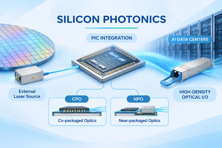
A CPO system places optical engines close to the switch ASIC, typically on a common package substrate or within a closely integrated package assembly. The electronic chip handles switching and data processing, while the optical engines perform electrical-to-optical and optical-to-electrical conversion.
The architecture requires several components to operate as a coordinated system:
Switch ASIC: Processes network packets and manages high-speed data movement across the switching fabric.
Electronic integrated circuit (EIC): Provides electrical functions such as driver and receiver circuitry for the optical interface.
Photonic integrated circuit (PIC): Contains optical functions such as waveguides, modulators, and photodetectors.
Laser source: Supplies optical power to the photonic circuit. It may be integrated or provided through an external laser architecture.
Optical coupling interface: Connects the photonic engine to fiber arrays or other optical routing structures.
Package substrate: Provides electrical connections, mechanical support, and integration between the switching and optical components.
The exact implementation varies by vendor and platform. Some designs integrate electronic and photonic components within a shared package, while others use chiplets or closely connected optical engine assemblies. CPO therefore describes an integration approach rather than one universally fixed component layout.
3. Shorter Electrical Paths Improve High-Speed Signal Transmission
One of the main engineering motivations for CPO is reducing the distance that high-speed electrical signals travel before optical conversion. In conventional pluggable architectures, signals pass through multiple electrical structures between the switch ASIC and the front-panel module.
As signaling rates increase, these channels experience frequency-dependent attenuation, reflections, crosstalk, and other impairments. Maintaining signal quality can require more complex equalization and signal-conditioning circuits.
Placing optical engines close to the ASIC reduces the length of the high-speed electrical connection. This can help lower channel loss and reduce the power required to maintain signal integrity.
| Engineering Factor | Traditional Pluggable Optics | CPO Architecture |
|---|---|---|
| Optical Engine Position | Installed in a front-panel module | Located close to the switch ASIC |
| Electrical Signal Path | Runs through package, PCB traces, and connectors | Shortened through package-level integration |
| Signal Conditioning | May require substantial equalization or retiming depending on the channel | Can reduce some channel compensation requirements |
| Bandwidth Density | Constrained by front-panel ports and electrical routing | Can support higher optical I/O density around the ASIC |
| Serviceability | Individual modules are generally replaceable | Optical engine servicing may involve more complex system-level procedures |
| System Design | Uses established pluggable interfaces | Requires coordinated ASIC, photonic, package, and thermal design |
The power benefit depends on the complete system architecture, including the electrical interface, optical engine, laser arrangement, cooling solution, and optical reach. CPO should not be assumed to deliver the same power reduction in every implementation.
4. Silicon Photonics Provides a Foundation for CPO Development
Silicon photonics is an important technology for CPO because it enables multiple optical functions to be integrated on a photonic chip using semiconductor manufacturing processes. Optical waveguides can route light across the chip, while modulators and photodetectors perform the conversion functions required for high-speed communication.
Silicon is suitable for building compact photonic circuits, but it does not efficiently generate light at common communication wavelengths. As a result, many silicon photonics architectures use external or hybrid-integrated laser sources made from other semiconductor materials.
Important silicon photonics components include:
Optical waveguides: Guide light between photonic components with controlled optical paths.
Modulators: Encode electrical data onto an optical carrier.
Photodetectors: Convert received optical signals into electrical current.
Wavelength multiplexers: Combine or separate optical channels in wavelength-division multiplexing architectures.
Optical couplers: Transfer light between the photonic chip and external fiber interfaces.
Laser sources: Provide the optical carrier required for transmission.
Silicon photonics can reduce component size and support multi-channel integration. Its role in CPO is particularly important because optical engines must deliver high aggregate bandwidth within a compact package area.
5. Electronic-Photonic Integration Requires Advanced Packaging
CPO depends on more than placing an optical chip beside a switch ASIC. The electronic and photonic components must be connected through a package architecture that supports high-speed electrical signaling, optical alignment, mechanical stability, and heat removal.
Advanced packaging techniques help bring these components together while managing the different physical requirements of electronic and photonic devices.
| Integration Technology | Role | Engineering Considerations |
|---|---|---|
| 2.5D Packaging | Connects multiple dies through an interposer or advanced substrate | Routing density, interposer design, power delivery, and thermal behavior |
| Chiplet Integration | Combines specialized electronic and photonic dies within one system | Die-to-die interfaces, packaging yield, and component compatibility |
| Silicon Photonics Integration | Combines optical waveguides and photonic functions on a chip | Optical loss, process variation, and coupling efficiency |
| Hybrid Integration | Combines different semiconductor materials and optical components | Material compatibility, alignment, and manufacturing complexity |
| Fiber Array Attachment | Connects the optical engine to external fiber paths | Position accuracy, connector reliability, and insertion loss |
Electronic and photonic components do not always share the same manufacturing process or material requirements. Advanced packaging must therefore bridge different fabrication technologies while maintaining reliable electrical and optical interfaces.
6. External Laser Sources and Optical Power Management
Laser integration is a major design consideration in CPO. Optical engines require stable light sources, but integrating lasers directly into a high-temperature switching package can create reliability and thermal challenges.
Some CPO architectures therefore use external laser sources. In these designs, laser light is delivered to the optical engines through optical connections rather than requiring every laser to be integrated directly beside the switching ASIC.
External laser architectures can provide several system-level advantages:
Separate laser components from some of the heat generated by switching silicon.
Allow laser sources to be managed independently of the main package.
Support centralized optical power delivery to multiple optical engines.
Provide a potential serviceability path for laser-source components.
Offer flexibility in laser redundancy and optical power management, depending on the system design.
However, external laser delivery introduces additional optical interfaces and distribution paths. Designers must account for coupling loss, optical power margins, connector reliability, and the consequences of a laser-source failure.
Laser architecture is therefore a system-level decision. The best approach depends on optical engine design, power requirements, thermal limits, redundancy strategy, and maintenance procedures.
7. Thermal Management Becomes a Critical Integration Challenge
High-performance switch ASICs generate substantial heat, and CPO places sensitive photonic components close to these high-power electronic devices. Temperature variations can affect laser behavior, optical wavelength characteristics, modulator performance, and package reliability.
Thermal management must therefore consider both electronic and optical components rather than treating the optical engine as an independent module.
Key design considerations include:
ASIC heat removal: High-power switching silicon requires effective cooling within a compact package.
Optical component temperature: Photonic devices may have different thermal operating requirements from the ASIC.
Temperature gradients: Uneven heating can affect optical alignment and wavelength stability.
Package materials: Differences in thermal expansion can create mechanical stress.
Cooling architecture: Air cooling and liquid cooling solutions must be evaluated against the complete package design.
Laser temperature control: Stable laser operation is important for optical power and wavelength performance.
Thermal design is closely connected to optical reliability. A package that achieves high bandwidth density but cannot maintain stable operating conditions may face limitations in long-term deployment.
8. CPO, NPO, LPO, and Pluggable Optics Follow Different Integration Paths
CPO is part of a broader evolution in optical and electrical integration. Other architectures, including Near-Packaged Optics (NPO) and Linear Pluggable Optics (LPO), address some of the same bandwidth and power challenges through different physical arrangements.
| Technology | Integration Position | Primary Design Direction | Important Consideration |
|---|---|---|---|
| Pluggable Optics | Front-panel module | Replaceable optical interfaces with established deployment practices | Electrical channel loss and module power at higher speeds |
| LPO | Front-panel module | Reduces or removes DSP functions in the optical module in supported designs | Requires careful host and channel signal-integrity design |
| NPO | Near the switch ASIC, generally on the board or package platform | Shortens electrical paths while retaining a degree of physical separation | Serviceability and optical connection design |
| CPO | Within a closely integrated ASIC package architecture | Places optical engines close to switching silicon | Advanced packaging, thermal design, and system-level maintenance |
These technologies should not be treated as interchangeable product types. Each represents a different balance between electrical path length, optical integration, serviceability, manufacturing complexity, and system design.
Pluggable optics remain useful for many current deployments because they provide flexible replacement and established host interfaces. NPO and CPO are intended for systems where higher integration and bandwidth density justify more complex packaging and maintenance approaches.
9. CPO Enables New Directions in 800G, 1.6T, and Higher-Speed Networks
As data center switch capacity increases, optical I/O must support higher aggregate bandwidth within increasingly constrained physical and power budgets. CPO is being developed as one approach to supporting these next-generation switching platforms.
The relationship between CPO and network data rates is not a simple one-to-one mapping. A CPO system may support multiple optical engines and channels, with aggregate bandwidth determined by the number of lanes, signaling rate, and system architecture.
| Network Development | Optical Integration Requirement | Engineering Focus |
|---|---|---|
| 400G | Established pluggable optical interfaces and early integrated optical approaches | Multi-lane signaling and optical module interoperability |
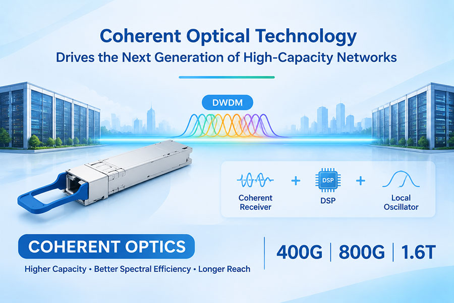
| 800G | Higher-density optical engines and advanced pluggable modules | 200G-class electrical lanes, power, and thermal design |
| 1.6T | Higher aggregate optical I/O capacity and more compact integration | Higher lane rates, package routing, and optical engine density |
| 3.2T and Beyond | Further advances in optical I/O and photonic integration | 400G-per-lane development, advanced packaging, and manufacturing scalability |
The CPX Multi Source Agreement provides one example of the industry's move toward more standardized high-density optical connectivity. Its September 2026 specification describes a mixed-media form factor supporting up to 7.2 Tb/s per socket based on 200 Gb/s-per-lane signaling.
Open interface specifications can help reduce dependence on proprietary optical connections and encourage broader ecosystem participation. However, practical interoperability still depends on implementation details, qualification, and system-level validation.
10. Manufacturing and Optical-Electrical Testing Must Evolve
CPO introduces manufacturing requirements that differ from conventional pluggable optical modules. Optical engines must be accurately positioned, coupled to fiber interfaces, electrically connected, and tested within a complex package environment.
Optical alignment is particularly demanding because small positioning errors can affect coupling efficiency and optical loss. At the same time, electrical performance must be validated across high-speed interfaces and integrated package structures.
Production testing commonly involves several measurement areas:
| Testing Area | Measurement Focus | Production Objective |
|---|---|---|
| Optical Coupling | Alignment accuracy, coupling efficiency, and insertion loss | Confirms reliable light transfer between the PIC and fiber interface |
| Optical Performance | Output power, wavelength, extinction ratio, and receiver characteristics | Validates optical transmission and reception |
| Electrical Performance | High-speed signal integrity, lane performance, and electrical interfaces | Verifies electronic-to-photonic signal conversion |
| Thermal Testing | Temperature response and operating stability | Evaluates performance under expected thermal conditions |
| Reliability Testing | Environmental stress, aging, and operating stability | Supports long-term product qualification |
| System-Level Testing | Integrated switch and optical engine operation | Confirms performance within the target platform |
TrendForce reported in October 2026 that CPO manufacturing is increasing demand for integrated optical-electrical testing platforms. Coordinating optical instruments, electrical measurements, alignment systems, and automated test software is becoming important for improving production throughput and reducing testing costs.
As CPO production scales, manufacturers will need to improve testing speed, process consistency, optical coupling yield, and failure analysis. These capabilities will influence how quickly the technology can move from engineering qualification to high-volume production.
11. Reliability, Repairability, and Deployment Considerations
CPO changes how optical components are accessed and maintained. With pluggable optics, a failed module can generally be removed and replaced without replacing the entire switch. In CPO systems, optical engines are integrated much more closely with the switching package, making component-level replacement more complicated.
This difference affects system availability, spare-part planning, repair procedures, and the total cost of ownership.
Important deployment considerations include:
Optical engine reliability: Photonic components must maintain stable performance over the intended operating life.
Laser-source reliability: External or integrated laser arrangements need suitable monitoring and failure-management strategies.
Fiber interface durability: Optical connections must withstand installation, handling, and maintenance requirements.
Package-level repair: Operators need clear procedures for diagnosing and servicing integrated optical systems.
Redundancy: System architecture should account for potential optical engine and laser-source failures.
Qualification: Environmental, thermal, and operational testing must reflect the actual deployment conditions.
For large data center operators, the decision to adopt CPO will depend not only on bandwidth and power efficiency but also on reliability, serviceability, manufacturing maturity, and overall system economics.
12. Industry Developments Accelerate CPO Commercialization
CPO development is progressing across switch silicon, photonic integration, packaging, optical connectivity, and production testing. Industry activity is increasingly focused on complete system platforms rather than individual optical components.
Several developments illustrate this direction:
Advanced switch integration: Switch manufacturers are developing platforms that bring optical engines closer to high-performance switching silicon.
Silicon photonics investment: Photonic integration is advancing to support higher channel density and more compact optical engines.
External laser architectures: Laser distribution and optical power management are receiving greater attention as CPO systems become more complex.
Open interface initiatives: Multi-source specifications are working toward more consistent optical and mechanical interfaces.
Automated production testing: Optical-electrical test integration is becoming a priority for manufacturing scale-up.
TrendForce identified 2027 as an important period for the convergence of CPO testing architectures and equipment investment, while 2028 is expected to be significant for evaluating readiness for larger-scale production. These are industry forecasts rather than guaranteed deployment milestones.
The broader transition will depend on manufacturing yield, thermal reliability, optical coupling performance, supply-chain capacity, and customer qualification. CPO commercialization is therefore likely to progress through specific system platforms and applications rather than through an immediate industry-wide replacement of pluggable optics.
13. C-LIGHT Connectivity Solutions for Evolving Optical Networks
As optical integration develops, conventional pluggable transceivers and high-speed cable assemblies remain important for current data center deployments. CPO is a system-level packaging architecture, while pluggable optical modules and active cables address different connectivity requirements across servers, switches, and network layers.
C-LIGHT provides high-speed optical and electrical connectivity products for data centers, AI infrastructure, and high-performance networking applications.
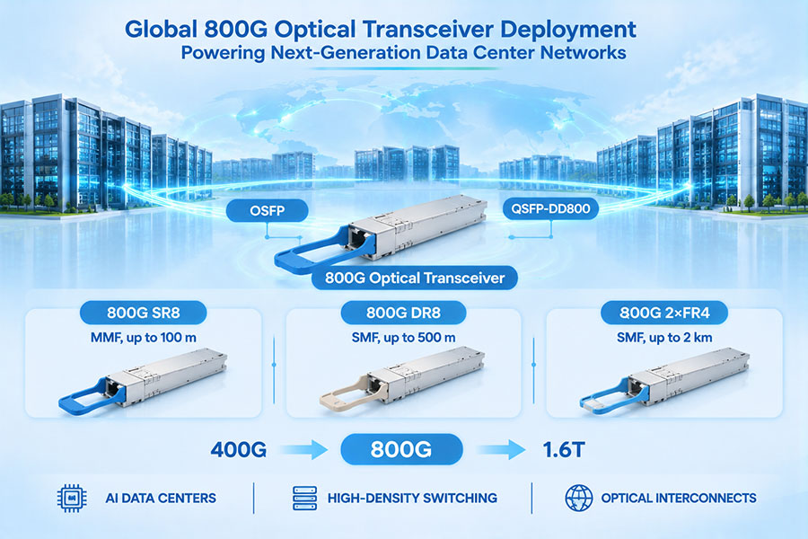
C-LIGHT 800G OSFP Optical Transceiver – Supports multiple configurations, including SR8, DR8, and 2×FR4, for different fiber types and data center transmission distances.
C-LIGHT 1.6T OSFP-RHS Optical Transceiver – Provides a 1.6T interface using an 8×200G PAM4 architecture for compatible next-generation network platforms.
C-LIGHT 800G AEC Cable – Provides active electrical connectivity for compatible high-speed server and rack-level connections.
C-LIGHT 800G AOC Cable – Integrates optical transmission into a cable assembly for compatible short- and medium-distance data center links.
C-LIGHT 400G QSFP-DD Optical Transceiver – Offers multiple optical configurations for existing high-capacity Ethernet and data center networks.
C-LIGHT DAC, AEC, ACC, and AOC Solutions – Covers different electrical and optical interconnection requirements for high-speed network equipment.
These products are not CPO optical engines. They provide connectivity options for conventional pluggable and cable-based network architectures that continue to coexist with the development of NPO and CPO.
For network operators planning infrastructure upgrades, selecting the appropriate technology requires evaluating port bandwidth, electrical channel limitations, fiber reach, power consumption, host compatibility, cooling requirements, and maintenance procedures.
14. Future Directions for Optical and Electrical Integration
The development of CPO reflects a broader shift in data center architecture. As computing and switching silicon become more powerful, the interfaces connecting these components must deliver greater bandwidth without allowing power consumption, signal loss, and physical complexity to increase at the same rate.
Several technology directions are likely to influence future optical integration:
Higher-speed optical I/O: Advances in 200G-per-lane and future 400G-per-lane technologies will increase aggregate optical bandwidth.
More advanced photonic integration: Silicon photonics and hybrid integration will support compact, multi-channel optical engines.
Improved package architectures: Advanced substrates and chiplet integration will help connect electronic and photonic components.
More efficient laser delivery: External laser systems and improved optical power management will support different CPO designs.
Integrated thermal solutions: Cooling architectures will need to accommodate both high-power ASICs and sensitive optical components.
Standardized optical interfaces: Industry specifications may improve interoperability and expand the supplier ecosystem.
Automated manufacturing: Faster alignment, integrated testing, and improved process control will be essential for production scaling.
CPO will not eliminate every electrical or pluggable optical connection. Instead, future data centers are likely to use a combination of pluggable optics, active cables, NPO, CPO, and other optical I/O technologies according to the bandwidth, distance, power, and serviceability requirements of each network layer.
15. Conclusion
CPO technology is driving new developments in optical and electrical integration by bringing photonic functions closer to high-performance switching silicon. Shorter electrical paths can help address signal integrity and power challenges as data center bandwidth increases, while silicon photonics and advanced packaging enable more compact optical engines.
The transition also introduces new engineering requirements. Thermal management, external laser delivery, optical coupling, package reliability, manufacturing yield, and integrated optical-electrical testing will all influence the commercial development of CPO systems.
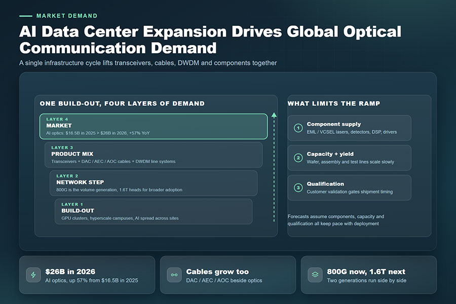
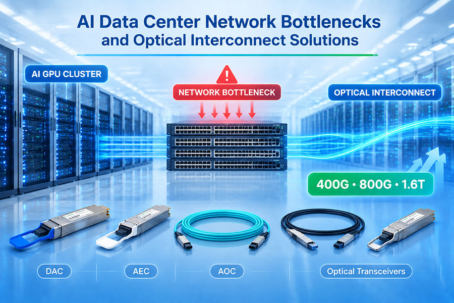
As AI data centers move toward higher-capacity 800G, 1.6T, and future optical interfaces, CPO and NPO will become increasingly important areas of development. At the same time, pluggable optical transceivers, DAC, AEC, and AOC products will continue to serve established network architectures and applications where flexibility and serviceability remain important.
The future of high-speed networking will depend on the coordinated development of electronic processing, photonic integration, optical connectivity, and advanced packaging. CPO represents an important step toward more tightly integrated and energy-efficient optical communication systems.
For high-speed optical transceivers, active cables, and data center connectivity solutions, Contact C-LIGHT for product information, technical support, and customized connectivity requirements.
 >

 >
 >
 >
 >
 >
 >
 >