TEL:+86 132 6656 7067





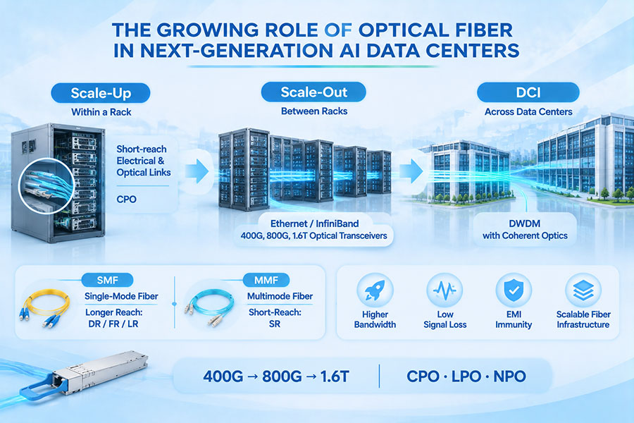
The construction of AI data centers is changing the requirements for physical network infrastructure. Large GPU clusters, high-performance computing systems, and distributed storage environments require extensive connections between servers, switches, racks, and buildings. As network speeds move from 400G toward 800G and 1.6T, fiber optic connectivity is becoming a fundamental part of data center design rather than simply a supporting cabling layer.
Unlike conventional enterprise facilities, AI data centers can contain thousands of high-bandwidth optical links across dense computing environments. Their network infrastructure must accommodate high fiber counts, short installation schedules, predictable transmission performance, and future expansion. This is increasing demand for single-mode and multimode fiber assemblies, MPO/MTP connectors, pre-terminated trunk cables, and structured fiber distribution systems.
1. Why AI Data Center Construction Requires More Fiber Connectivity
AI workloads create substantial communication requirements between computing accelerators. Distributed training, parameter synchronization, storage access, and data exchange place significant demands on the network connecting individual servers and racks.
These networks often use high-speed Ethernet or InfiniBand architectures. As port speeds increase, the number and density of optical connections also grow. A single AI cluster may require extensive connections across server racks, leaf switches, spine switches, storage systems, and network distribution areas.
Several factors are contributing to higher fiber demand:
Higher network bandwidth: 400G, 800G, and emerging 1.6T interfaces increase the capacity requirements of optical connections.
Larger GPU clusters: More computing nodes create additional connections between servers and network switches.
Higher rack density: Dense computing environments require compact cabling and organized fiber distribution.
Multi-building campuses: Large AI facilities need fiber infrastructure between buildings and separate equipment areas.
Future expansion: Fiber pathways must accommodate network upgrades without requiring extensive reconstruction.
The result is a growing need for carefully planned fiber infrastructure throughout the data center construction process.
2. Fiber Connectivity Across Different Data Center Network Layers
AI data center fiber infrastructure is not limited to connections between servers and switches. Different network layers have different transmission distances, bandwidth requirements, and physical connectivity arrangements.
| Network Layer | Main Connectivity | Typical Fiber Requirement | Key Consideration |
|---|---|---|---|
| Server to ToR switch | GPU servers and top-of-rack switches | Multimode or single-mode, depending on distance and optics | Port density and short-reach connectivity |
| Leaf to spine | Switch-to-switch connections | High-density multimode or single-mode fiber | Bandwidth and port scalability |
| Rack to rack | Connections between equipment racks | Structured fiber assemblies and trunk cables | Cable routing and fiber management |
| Building to building | Data center campus interconnection | Primarily single-mode fiber | Distance, pathway capacity, and environmental protection |
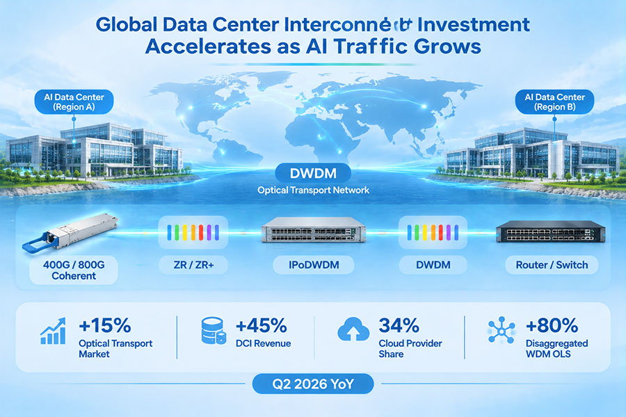
| Data center to data center | Regional and metropolitan DCI | Single-mode fiber and suitable optical transport systems | Transmission distance and optical link budget |
The exact fiber architecture depends on the network topology and selected optical transceivers. A design intended for short-reach multimode links cannot automatically be reused for long-distance single-mode connections.
3. Single-Mode and Multimode Fiber Selection
Single-mode fiber (SMF) and multimode fiber (MMF) serve different roles in AI data center infrastructure. Choosing the correct fiber type affects optical transceiver selection, transmission distance, cabling cost, and future network flexibility.
Multimode fiber is commonly used for short-distance connections inside data centers. OM3 and OM4 are established multimode categories, while OM5 is designed to support wideband multimode applications. Single-mode fiber provides a broader transmission-distance range and is widely used for higher-speed links where distance and future scalability are important.
| Fiber Type | Core Characteristics | Common Applications | Selection Considerations |
|---|---|---|---|
| OM3 | 50/125 μm multimode fiber | Legacy and selected short-reach data center links | Existing infrastructure and supported optical reach |
| OM4 | 50/125 μm enhanced multimode fiber | High-speed short-reach optical connections | Bandwidth and distance requirements |
| OM5 | 50/125 μm wideband multimode fiber | Supported short-reach wideband applications | Transceiver wavelength compatibility |
| OS2 | Single-mode fiber | High-speed links, campus networks, and DCI | Longer reach and network expansion |
For new AI data center construction, the choice should be based on the actual optical interface specifications rather than assuming that one fiber category is suitable for every link. Transceiver wavelength, connector configuration, insertion loss, and supported transmission distance must all match the installed cabling.
4. MPO and MTP Connectors Support High-Density Fiber Deployment
As the number of optical ports increases, traditional duplex fiber patching can become difficult to manage at scale. MPO and MTP multi-fiber connectivity provides a more compact way to organize parallel optical connections.
These connectors combine multiple optical fibers into a single connector interface. They are widely used in structured cabling systems, trunk assemblies, fiber distribution panels, and compatible parallel-optics applications.
MPO is the general connector standard, while MTP is a branded, enhanced MPO connector product family. Both are used in high-density optical infrastructure, but connector quality, mechanical performance, polarity, and compatibility should be verified for the specific assembly.
Common configurations include:
8-fiber assemblies: Used in compatible parallel optical interfaces and breakout cabling.
12-fiber assemblies: Common in established high-density fiber distribution systems.
24-fiber assemblies: Help increase fiber capacity within a compact connector arrangement.
Higher-density solutions: Newer connector formats can support further increases in fiber density where the equipment ecosystem supports them.
Connector fiber count alone does not determine compatibility. The optical module interface, fiber positions, polarity, key orientation, and patch-panel arrangement must be checked together.
5. Pre-Terminated Fiber Trunk Cables Accelerate Construction
Large AI data center projects often involve extensive cabling across multiple racks and equipment areas. Field termination of every connection can increase installation time and introduce additional variability in connector quality.
Pre-terminated fiber trunk cables provide an alternative. These assemblies are manufactured and connectorized before delivery, allowing installation teams to connect prepared cable assemblies to compatible distribution panels and equipment.
Common advantages include:
Faster installation: Factory-terminated assemblies reduce the amount of field connectorization required.
Consistent connector quality: Controlled manufacturing and inspection help improve assembly consistency.
Better cable organization: Trunk designs support structured routing between racks and distribution areas.
Reduced installation variability: Predefined cable lengths and connector configurations reduce field-dependent work.
Scalable deployment: Standardized assemblies make it easier to replicate cabling arrangements across equipment rows.
However, pre-terminated assemblies still require careful planning. Cable length, connector gender, polarity, fiber type, breakout arrangement, and routing paths must be confirmed before production and installation.
6. Fiber Polarity and Connector Compatibility in High-Speed Networks
Fiber polarity is an important part of structured cabling design. In duplex and parallel optical systems, the transmit and receive paths must connect correctly between the two endpoints. Incorrect polarity can prevent a link from establishing even when the fiber itself passes basic continuity testing.
AI data center networks may contain large numbers of MPO/MTP trunk cables, adapter panels, and breakout assemblies. A consistent polarity plan helps avoid connection errors during installation and later maintenance.
Key design considerations include:
Connector gender: Confirm whether each connector requires pins or is pinless according to the mating interface.
Polarity method: Establish a consistent Type A, Type B, or Type C arrangement where applicable.
Fiber mapping: Verify the relationship between individual fiber positions and optical channels.
Breakout configuration: Confirm how multi-fiber connectors map to duplex LC or other endpoint interfaces.
End-to-end compatibility: Check the entire path, including trunk cables, adapter panels, and patch cords.
Polarity should be documented in the cabling design and verified during commissioning. Relying on connector appearance alone is not sufficient for complex high-density installations.
7. 800G and 1.6T Optical Modules Increase Fiber Infrastructure Requirements
The transition to 800G and 1.6T optical connectivity is increasing the importance of fiber infrastructure planning. Higher-speed transceivers use different optical architectures, lane configurations, and connector interfaces, which can affect the required fiber assemblies.
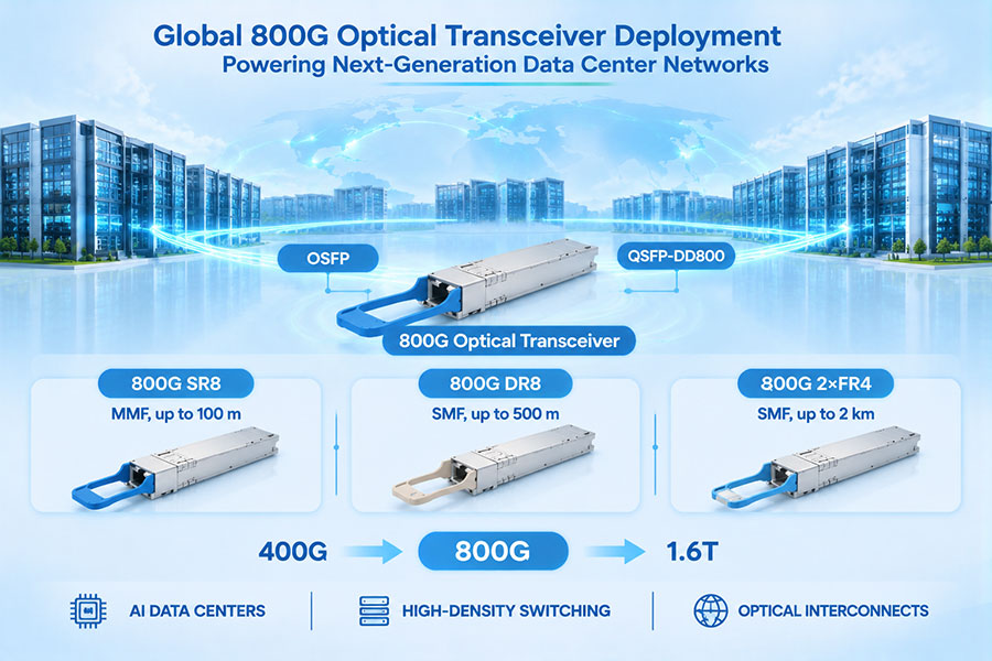
For example, 800G optical modules may use parallel optical interfaces such as SR8 or DR8, or wavelength-division architectures such as 2×FR4. These configurations do not necessarily use the same fiber cabling arrangement.
| Optical Technology | Typical Architecture | Fiber Connectivity Considerations |
|---|---|---|
| 400G SR8 | Parallel multimode optics | Multi-fiber MPO connectivity according to the module specification |
| 400G DR4 | Parallel single-mode optics | Single-mode multi-fiber connectivity |
| 800G SR8 | Parallel multimode optics | High-density multimode fiber assemblies |
| 800G DR8 | Parallel single-mode optics | Single-mode multi-fiber assemblies with the specified connector mapping |
| 800G 2×FR4 | Two optical channels using wavelength multiplexing | Duplex fiber connectivity for each optical interface, subject to module design |
| 1.6T optical modules | Multiple high-speed optical lanes | Connector and fiber mapping depend on the specific 1.6T architecture |
The move to higher data rates does not mean every optical link requires more physical fibers. Parallel optics, wavelength multiplexing, and lane-rate improvements can produce different fiber-count requirements. The correct cabling design must follow the selected module's optical interface specification.
For this reason, fiber infrastructure planning should take place alongside transceiver selection, switch architecture design, and network topology development.
8. Fiber Distribution and Cable Management in AI Data Centers
High-density AI environments can contain extensive fiber bundles connecting servers, switches, patch panels, and distribution frames. Without a structured cable management plan, installation complexity can increase as the facility expands.
Fiber distribution systems help organize these connections and provide accessible points for testing, patching, and future network changes.
Important infrastructure elements include:
Fiber distribution frames: Provide centralized termination and patching points.
Rack-mounted fiber panels: Organize connections within individual equipment rows.
MPO/MTP adapter panels: Support high-density multi-fiber distribution.
Horizontal and vertical cable managers: Guide fiber routes and reduce cable congestion.
Overhead cable pathways: Separate and organize large cable bundles across equipment areas.
Identification systems: Provide clear labels for cable routes, endpoints, and fiber positions.
Fiber bend radius is another important consideration. Excessive bending, compression, or poorly secured cable bundles can increase attenuation or cause physical damage. Installation designs should follow the cable manufacturer's minimum bend-radius and pulling-tension requirements.
9. Fiber Testing and Quality Control During Construction
Fiber connectivity must be tested before a new AI data center network enters operation. A connector that appears physically intact may still have contamination, excessive insertion loss, or an incorrect fiber mapping.
Testing should be integrated into manufacturing, installation, and commissioning rather than treated as a final inspection step only.
| Test Method | Purpose | Typical Inspection Focus |
|---|---|---|
| Visual inspection | Check connector end-face condition | Contamination, scratches, and physical defects |
| Insertion loss testing | Measure optical loss through the connection | End-to-end attenuation |
| Return loss testing | Evaluate reflected optical power | Connector and termination quality |
| OTDR testing | Analyze fiber links and locate events | Splices, connectors, bends, and link discontinuities |
| Polarity verification | Confirm correct fiber mapping | Transmit and receive path alignment |
| Continuity testing | Verify that the intended fiber path is connected | Open circuits and incorrect connections |
Different tests provide different information. For example, an insertion loss test measures the overall attenuation of a link, while OTDR testing helps locate events along the fiber. Both may be required depending on the project specifications and link architecture.
Cleanliness is especially important for MPO/MTP connectors because contamination can affect multiple fiber channels simultaneously. Inspection and cleaning procedures should be included in installation and maintenance workflows.
10. Fiber Infrastructure Planning for Multi-Building AI Campuses
Many large AI data center projects are developed as multi-building campuses rather than single facilities. Separate buildings may contain computing halls, storage systems, network rooms, power infrastructure, and operational facilities.
These environments require fiber routes between buildings in addition to internal rack-level connectivity. The campus backbone must account for distance, pathway availability, cable protection, redundancy, and future capacity requirements.
Single-mode fiber is commonly used for inter-building connections because it supports a broad range of transmission distances and optical technologies. Depending on the network design, the campus may also require distribution frames, splice enclosures, outdoor-rated cable, and diverse physical routes.
Redundant fiber paths can improve network resilience when they are physically separated and designed to avoid shared failure points. Two cables routed through the same vulnerable pathway do not necessarily provide meaningful physical redundancy.
Campus fiber planning should therefore consider the full route from building entrance facilities to internal distribution points, not just the number of fibers required at each endpoint.
11. How to Plan Fiber Connectivity Before AI Data Center Construction
Fiber infrastructure decisions made during the design stage can affect construction schedules, equipment placement, operating costs, and future upgrade options. A structured planning process helps align cabling requirements with the network architecture.
Important planning steps include:
Define the network topology: Identify server, leaf, spine, storage, campus, and DCI connections.
Determine bandwidth requirements: Establish current and expected port speeds for each network layer.
Select optical interfaces: Identify the transceiver type, fiber type, connector, and supported reach for each link.
Calculate fiber quantities: Include active connections, spare fibers, redundant routes, and future expansion capacity.
Design structured cabling: Specify trunk assemblies, patch panels, breakout cables, polarity, and cable pathways.
Coordinate installation: Align cable delivery, rack installation, and network equipment deployment schedules.
Establish acceptance criteria: Define inspection, insertion loss, polarity, and other required test procedures.
Fiber counts should be derived from actual port mappings and the selected optical architectures. Adding spare capacity is valuable, but an arbitrary fiber-count target may increase construction cost without addressing the real bottlenecks in the network design.
12. C-LIGHT Fiber Optic Connectivity Solutions for AI Data Centers
C-LIGHT provides optical transceivers, high-density fiber assemblies, and related connectivity products for data centers, AI infrastructure, high-performance computing, and high-speed Ethernet networks. These products address different parts of the physical connectivity layer, from optical signal transmission to fiber distribution.
C-LIGHT MPO-MPO fiber patch cables support multi-fiber connectivity for high-density optical networks. Available configurations include 8-, 12-, and 24-fiber options, with single-mode G657A2 and multimode OM3/OM4 fiber choices listed in the product specifications. The product page specifies insertion loss of ≤0.5 dB.
These assemblies can be used in compatible parallel optical systems, fiber distribution panels, and structured data center cabling installations.
Product details: C-LIGHT MPO-MPO Fiber Patch Cable
C-LIGHT MTP-MTP fiber patch cables provide multi-fiber connectivity with MTP connectors at both ends. The product range includes different fiber counts and fiber types for high-density optical distribution and compatible parallel transmission applications.
These assemblies can help organize connections between fiber panels, equipment racks, and optical network components.
Product details: C-LIGHT MTP-MTP Fiber Patch Cable
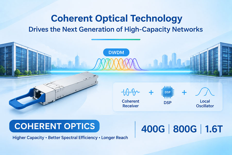
C-LIGHT 800G OSFP optical transceivers cover multiple application types, including SR8, DR8, and 2×FR4 configurations. These options address different fiber types and transmission distances in high-speed data center networks.
The correct fiber assembly should be selected according to the specific transceiver connector and optical interface requirements.
Product details: C-LIGHT 800G OSFP Optical Transceivers
C-LIGHT 1.6T OSFP-RHS solutions support next-generation high-bandwidth network platforms. The listed product configurations include 2×800G optical interfaces, with model-specific DR4 and FR4 transmission options.
As 1.6T deployments develop, matching the optical module, host platform, connector arrangement, and fiber distribution system will be increasingly important.
Product details: C-LIGHT 1.6T OSFP-RHS Optical Transceivers
By combining optical transceivers with compatible MPO/MTP cabling and fiber distribution components, network designers can develop connectivity architectures suited to different AI data center requirements. Product selection should always be based on the actual link design, connector mapping, transmission distance, and host compatibility.
13. Future Trends in AI Data Center Fiber Connectivity
AI data center construction is expected to continue increasing the scale and complexity of optical infrastructure. Higher-speed Ethernet, larger accelerator clusters, and multi-building computing campuses will place additional demands on fiber capacity and cable management.
Several developments are likely to influence future cabling designs:
Higher fiber density: More optical connections will require compact connectors, structured trunk systems, and improved distribution methods.
800G and 1.6T adoption: New optical interfaces will require updated connector and fiber mapping plans.
Pre-terminated cabling: Factory-assembled trunk systems can help standardize installation in large construction projects.
Advanced connector formats: Smaller, higher-density connector ecosystems may become more important in space-constrained environments.
Greater campus connectivity: Multi-building AI infrastructure will require larger backbone capacity and carefully planned redundant routes.
Improved testing and documentation: Larger fiber networks will require more systematic inspection, labeling, and lifecycle management.
These changes indicate that fiber infrastructure must be designed as a long-term part of the AI data center architecture. A well-planned cabling system can support equipment upgrades and network expansion while reducing the need for disruptive physical reconstruction.
14. Conclusion
The growth of AI data center construction is increasing demand for high-density fiber optic connectivity across server racks, switching networks, equipment rooms, and multi-building campuses. As network speeds advance toward 800G and 1.6T, fiber infrastructure must support greater bandwidth, more optical connections, and increasingly complex physical layouts.
MPO/MTP connectors, pre-terminated trunk cables, single-mode and multimode fiber assemblies, and structured distribution systems are becoming essential components of modern data center construction. Their successful deployment depends on correct fiber selection, connector compatibility, polarity planning, installation quality, and comprehensive testing.
For AI infrastructure developers and network operators, investing in scalable fiber connectivity during the construction stage provides a foundation for future network expansion. The physical fiber layer will remain a critical part of high-performance data center architecture as optical technologies and computing requirements continue to evolve.
C-LIGHT provides high-speed optical transceivers, MPO/MTP fiber assemblies, and data center connectivity solutions for AI networks, HPC systems, and high-density optical infrastructure. Contact our team for product specifications, fiber connectivity options, and project-specific technical support.
 >

 >
 >
 >
 >
 >
 >
 >