TEL:+86 132 6656 7067




An 800G optical transceiver link can fail even when both modules are recognized by the switch and their diagnostic information appears normal. At 800GbE, successful operation depends on multiple factors, including optical power, lane mapping, fiber polarity, transmitter and receiver performance, forward error correction (FEC), host electrical interfaces, and module compatibility.
Unlike a simple link-down condition, an 800G link problem may also appear as intermittent connectivity, a high symbol error rate, rising corrected FEC errors, uncorrectable codewords, or degraded throughput. Effective troubleshooting requires identifying which part of the signal path is failing rather than replacing the optical module immediately.
1. Common Causes of 800G Optical Link Failure
| Failure Category | Typical Symptoms | Initial Checks |
|---|---|---|
| Optical power outside limits | Link fails to initialize, receiver signal is absent, or errors increase under load. | Check Tx/Rx power, receiver thresholds, fiber loss, and optical path connections. |
| Fiber polarity or lane mapping | Some lanes receive no signal, or the link fails to establish. | Verify fiber polarity, MPO/MTP mapping, breakout configuration, and lane assignments. |
| FEC or BER problems | High corrected errors, uncorrectable codewords, or frequent link retraining. | Check FEC mode, PCS status, pre-FEC BER, post-FEC errors, and lane-level counters. |
| Module compatibility | Module identification succeeds but the port remains down or operates unreliably. | Confirm form factor, supported module type, firmware, port configuration, and vendor requirements. |
| Host electrical signal integrity | Optical levels appear normal, but lane errors or link instability persist. | Inspect host SerDes status, electrical lane mapping, signal integrity, and supported host modes. |
| Thermal or power issues | Intermittent failures after warm-up, module alarms, or instability under heavy traffic. | Review module temperature, power alarms, airflow, heatsink contact, and port power limits. |
| Configuration mismatch | Physical signal is present, but the link does not reach the expected operational state. | Check speed, FEC, breakout mode, autonegotiation where applicable, and interface settings. |
2. Optical Power Problems
Optical power is one of the first parameters to check when an 800G link fails. However, a Tx or Rx power value within the module's specified range does not automatically prove that the entire optical channel is healthy.
Low receive power
Low received power can result from dirty connectors, damaged fiber, excessive insertion loss, incorrect connections, a faulty transmitter, or an optical path that does not match the module's reach specification. In multi-lane designs, the problem may affect only one lane or one group of lanes.
Excessive receive power
Some short-reach connections can deliver more optical power than the receiver is designed to accept. If received power exceeds the specified overload limit, the receiver may not meet its performance requirements even though the signal is strong.
Power imbalance between lanes
Parallel optical modules can use multiple independent optical channels. A single weak or missing lane may cause the overall link to fail or produce uncorrectable errors. Average power readings can hide a problem affecting an individual lane.
Check the transmitter and receiver diagnostics at both ends. Compare each lane against the module's datasheet limits and the platform's documented thresholds rather than using a universal power threshold for all 800G optics.
3. Fiber Polarity, Connector Quality, and Lane Mapping
800G optical links can use different optical architectures. Some use parallel optical lanes, while others use wavelength-division multiplexing. Connector type, fiber count, and lane assignment depend on the specific module, such as SR8, DR8, 2DR4, or 2FR4.
For parallel optics, the transmitter lanes must connect to the corresponding receiver lanes according to the module's optical interface specification. An incorrect MPO/MTP polarity or breakout mapping can leave some receiver channels without the intended signal.
Inspect connector end faces and clean them using approved fiber-cleaning procedures.
Verify the fiber type and connector interface against the transceiver specification.
Confirm MPO/MTP polarity, fiber positions, and lane mapping.
Check that breakout cables and fan-out assemblies use the correct channel assignment.
Confirm that the optical module's intended reach and fiber type match the installed link.
Do not assume that two modules with the same nominal data rate use the same fiber arrangement. An 800G SR8 module and an 800G DR8 module, for example, can have different optical requirements and should not be treated as interchangeable simply because both support 800G.
4. FEC Errors and High BER
Forward error correction is an essential part of high-speed Ethernet links. It allows the receiver to correct a defined level of transmission errors. The required FEC implementation depends on the Ethernet PHY and the specific module or host interface.
When the received signal quality deteriorates, the number of corrected errors may rise. If the error level exceeds the correction capability, uncorrectable codewords can occur and the link may become unstable or drop.
| Observed Condition | Possible Interpretation | Recommended Investigation |
|---|---|---|
| Corrected FEC counters increase slowly | The receiver is correcting transmission errors; the significance depends on the error rate and operating specification. | Compare counter growth over time and correlate it with lane BER, optical power, and traffic conditions. |
| Corrected FEC counters rise rapidly | The link may have limited signal margin or deteriorating signal quality. | Check optical channels, host SerDes status, cabling, temperature, and pre-FEC BER. |
| Uncorrectable FEC errors | Errors have exceeded the correction capability or another PHY-level issue is present. | Check FEC compatibility, lane alignment, signal quality, and physical connections. |
| Link repeatedly retrains or drops | Signal quality or link initialization may be unstable. | Correlate link events with FEC counters, module alarms, lane status, and platform logs. |
FEC counters must be interpreted in context. A nonzero corrected-error count is not necessarily evidence of a failed module. The rate of increase, uncorrectable errors, BER measurements, and applicable PHY requirements provide a more meaningful assessment.
Also distinguish between host electrical lanes and optical lanes. Depending on the 800G module architecture, the mapping between these lanes may not be one-to-one. A lane-level fault should be traced through the actual host, module, and optical mapping rather than assuming identical lane numbers at every stage.
5. Module Compatibility and Host Interface Issues
An 800G module may be detected by the switch without being fully supported in the selected operating mode. Module identification and successful initialization of the high-speed link are separate checks.
Compatibility problems may involve the form factor, supported module type, firmware, power requirements, host electrical interface, port mode, or platform-specific restrictions. A module can also report normal optical diagnostics while the host electrical interface fails to establish a reliable connection.
Confirm whether the switch supports the specific OSFP or QSFP-DD module and its optical type.
Check the vendor's compatibility information and recommended software or firmware versions.
Verify the configured port speed and whether the port is operating as a single 800G interface or in a supported breakout mode.
Check the host SerDes and PCS status, including lane alignment and link-training information where applicable.
Review module power and thermal requirements against the host platform's capabilities.
For multi-vendor deployments, verify both the module's interoperability requirements and the host platform's supported configuration. Physical fit and successful module identification alone do not guarantee full interoperability.
6. DSP, CDR, and Electrical Signal Integrity
High-speed optical modules rely on electrical and signal-processing functions that prepare transmitted data and recover received data. Depending on the module architecture, these may include digital signal processing (DSP), clock and data recovery (CDR), equalization, and forward error correction in the relevant part of the signal chain.
A failure in the host electrical path can cause link errors even when the optical output and receive power appear normal. Potential causes include excessive electrical channel loss, poor signal integrity, lane mapping problems, connector issues, and incompatible operating modes.
Useful checks include:
Host SerDes and PCS status, including lane lock and alignment information where available.
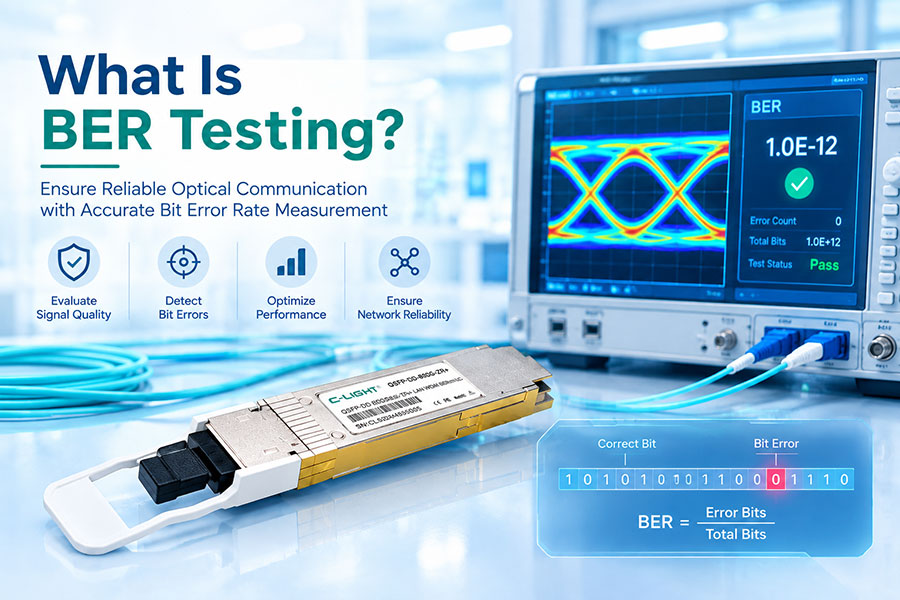
Pre-FEC BER and post-FEC error counters, when exposed by the platform.
Link-training or equalization status, if applicable to the electrical interface.
Module alarms, reset history, and relevant host logs.
Results from a known-good, supported module and port configuration.
Not all 800G modules expose the same diagnostics. Use the platform documentation to identify which counters are available and what each counter represents.
7. Thermal and Power-Related Failures
800G optical modules can have significant power and cooling requirements. Inadequate airflow, an incompatible thermal environment, or a platform power limitation can affect stability and may trigger alarms or protective behavior.
Thermal or power-related problems may appear after a module has been operating for some time, under sustained traffic, or when neighboring ports are heavily populated.
Check the module temperature against its documented operating range and alarm thresholds.
Inspect chassis airflow, fan operation, heatsink contact, and port placement requirements.
Review module power alarms and platform logs.
Check whether the host supports the module's power class and cooling requirements.
Compare the behavior across cold start, warm operation, and sustained load without exceeding vendor operating limits.
Do not diagnose a thermal fault solely from a high temperature reading. Compare the measurement with the specific module specification, platform limits, and alarm history.
8. Step-by-Step 800G Link Troubleshooting
A structured troubleshooting process helps isolate the failing layer while avoiding unnecessary replacement of working components.
Step 1: Confirm the physical and administrative state
Check whether the interface is administratively enabled, whether the module is detected, and whether the port reports link down, fault, or initialization failure. Record the exact error messages and recent link events.
Step 2: Collect diagnostics from both ends
Record module identity, temperature, voltage, transmit power, receive power, lane-level status, and alarm information where available. Compare the transmitter output at one end with the receiver measurement at the opposite end.
Step 3: Verify the optical path
Check connector cleanliness, fiber type, polarity, lane mapping, and cable compatibility. If appropriate, use a known-good compatible cable to isolate a cabling problem.
Step 4: Examine FEC and PHY counters
Check corrected and uncorrectable FEC errors, BER measurements, lane alignment, and PCS status. Clear counters only after recording the baseline, then observe how they change over a defined interval.
Step 5: Verify the host configuration
Confirm port speed, breakout mode, FEC settings, supported module type, firmware, and relevant host electrical status. Use the settings required by the applicable Ethernet interface and platform documentation.
Step 6: Isolate components systematically
Where supported, test a known-good compatible module, cable, or port one variable at a time. Follow platform procedures and avoid changing several components simultaneously, as that can obscure the original cause.
Step 7: Recheck under normal operating conditions
After correcting the suspected issue, verify link stability, lane status, optical power, and error-counter behavior. A link-up state alone is not sufficient if uncorrectable errors or other performance faults remain.
9. Diagnostic Checklist
| Check Item | What to Verify | Purpose |
|---|---|---|
| Module identification | Part number, form factor, supported module type, and alarms. | Identify detection and compatibility problems. |
| Optical diagnostics | Tx/Rx power by lane, temperature, and relevant thresholds. | Find optical power and environmental issues. |
| Fiber path | Connector condition, fiber type, polarity, and lane mapping. | Detect physical connection errors. |
| PHY and FEC | BER, corrected and uncorrectable errors, PCS status, and lane alignment. | Identify signal-quality or decoding issues. |
| Host configuration | Speed, FEC, breakout mode, firmware, and port support. | Detect configuration and interoperability problems. |
| Thermal and power | Module operating range, alarms, airflow, and host power support. | Identify environmental or platform limitations. |
| Controlled substitution | Known-good compatible module, cable, or port. | Isolate the faulty component or path. |
10. Frequently Asked Questions
Q1. Why is an 800G module detected but the link remains down?
Answer: Module detection confirms that the host can identify the device, but it does not prove that the electrical and optical links are operating correctly. Check port configuration, FEC, lane mapping, optical signal presence, host SerDes status, and module compatibility.
Q2. Can normal optical power readings still result in link failure?
Answer: Yes. Optical power readings do not directly measure every aspect of signal quality. Excessive noise, poor signal integrity, lane mapping errors, wavelength incompatibility, or receiver problems can still cause high BER and uncorrectable FEC errors.
Q3. Do corrected FEC errors mean that an 800G module is defective?
Answer: Not necessarily. FEC is designed to correct a certain level of transmission errors. Evaluate the counter growth rate, uncorrectable errors, BER, link stability, and applicable interface specifications before determining whether a fault exists.
Q4. Can an incorrect MPO/MTP polarity prevent an 800G link from coming up?
Answer: Yes. For parallel optical links, incorrect polarity or lane mapping can prevent signals from reaching their intended receive channels. Confirm the cable assembly and mapping against the specific module interface specification.
Q5. Should the optical module be replaced first?
Answer: Not usually. Record diagnostics and check the configuration, optical path, lane status, and error counters first. A known-good compatible module can then be used as a controlled substitution test if the initial checks do not identify the problem.
Q6. Why does an 800G link fail only after running for a while?
Answer: Intermittent or delayed failures may be associated with temperature, power conditions, changing signal quality, connector issues, or rising error rates. Correlate the failure time with module telemetry, alarms, FEC counters, and host logs.
11. Conclusion
An 800G optical transceiver link can fail because of optical power problems, fiber polarity errors, FEC or BER issues, host electrical signal integrity, module compatibility, configuration mismatches, or thermal and power limitations. These failure modes can produce similar symptoms, so diagnosis should be based on correlated evidence from both ends of the link.
A reliable troubleshooting process starts with module status and optical diagnostics, continues through fiber mapping and PHY/FEC analysis, and then isolates the host, cable, or transceiver using controlled tests. This approach helps reduce unnecessary replacements and supports more consistent operation in high-bandwidth data center networks.
800G Optical Connectivity Solutions
Review optical transceiver options for high-speed data center networks, including different form factors, reach requirements, and optical interface configurations.
Contact C-LIGHT >
>

 >
>
 >
>
 >
>
 >
>
 >
>
 >
>
 >
>