TEL:+86 132 6656 7067




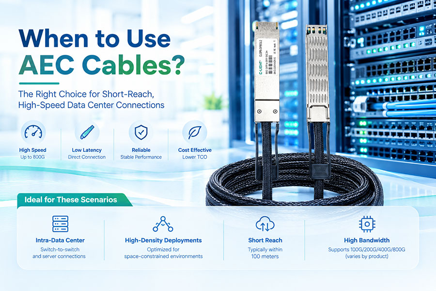
Active Electrical Cables (AEC) have emerged as one of the most important interconnect innovations for AI data centers. They occupy a critical middle ground between passive Direct Attach Copper (DAC), which is limited to very short distances, and Active Optical Cables (AOC), which offer longer reach but at higher cost and power. By integrating Retimer chips inside the cable connectors, AEC extends copper's reach to 5–7 meters—and in some implementations up to 9 meters—while consuming 25–50% less power than optical alternatives.
The global market for data center AEC cables was valued at approximately US$ 808 million in 2025 and is projected to reach US$ 3.58 billion by 2032, growing at a CAGR of 22.0%. This growth reflects the fundamental role AEC plays in AI infrastructure: connecting GPU clusters, spine-leaf fabrics, and storage networks where DAC cannot reach and where AOC's cost and power premium is difficult to justify.
But AEC is not a universal solution. It costs more than DAC, consumes more power than passive copper, and offers less reach than fiber. Understanding when AEC is the right choice—and when DAC, ACC, or AOC are better—requires a clear view of the trade-offs across distance, power, cost, and signal integrity.
1. What Is an AEC Cable?
An Active Electrical Cable is a factory-terminated copper assembly that integrates active signal-conditioning electronics—specifically Retimer chips—into the connector modules at each end. Unlike passive DAC, which relies solely on copper's electrical characteristics, AEC actively compensates for signal loss and degradation during transmission.
The core of AEC technology is the Retimer. A Retimer performs several critical functions that go beyond simple amplification:
Clock and Data Recovery (CDR): Extracts timing information from the incoming signal and regenerates a clean clock, eliminating accumulated jitter.
Signal Reshaping: Reconstructs the signal waveform to restore its original shape and amplitude, removing noise and distortion.
Equalization: Applies continuous-time linear equalization (CTLE) and decision-feedback equalization (DFE) to compensate for channel loss and intersymbol interference.
The signal path through an AEC can be understood as: switch or GPU → AEC connector → active signal conditioning → copper cable → active signal conditioning → AEC connector → remote switch or GPU. The active circuitry at each end ensures that the signal arriving at the receiver is clean enough to be reliably decoded, even after traveling through several meters of copper.
AEC cables are available in all standard form factors—QSFP28, QSFP56, QSFP-DD, OSFP, and OSFP-XD—and support data rates from 100G through 1.6T. The global production of data center AEC reached approximately 1.6 million units in 2025, with an average selling price of approximately US$ 504.5 per unit.
2. AEC vs. ACC: Retimer vs. Linear Equalizer
Before examining when to use AEC, it is essential to distinguish it from Active Copper Cable (ACC), another type of active copper interconnect. Both use copper as the transmission medium and both contain active electronics, but they differ fundamentally in the type of signal processing they apply.
| Characteristic | ACC (Active Copper Cable) | AEC (Active Electrical Cable) |
|---|---|---|
| Signal Processing Chip | ReDriver (linear equalizer) | Retimer (CDR + equalizer + reshaping) |
| Core Function | Amplifies and equalizes signal | Re-times, reshapes, and regenerates signal |
| Noise Handling | Amplifies signal and noise together | Removes noise, restores clean signal |
| Typical Reach at 400G | 3–4 meters | 5–7 meters |
| Typical Reach at 800G | 3–4 meters | 5–7 meters (up to 9 m in some designs) |
| Power Consumption | Lower | Moderate (higher than ACC, lower than AOC) |
| Jitter Handling | Cannot block jitter propagation | Blocks jitter propagation through CDR |
| Interoperability | May struggle with mixed-vendor deployments | Higher success rate in plug-and-play scenarios |
The key distinction is that ACC's linear equalizer amplifies the signal but also amplifies the noise that has accumulated during transmission. AEC's Retimer, by contrast, recovers the clock, samples the data, and regenerates a clean signal at the output—effectively removing the noise and jitter that accumulated during transmission. This makes AEC suitable for longer distances and more demanding signal integrity environments.
Molex notes that Retimers provide a higher chance of success in plug-and-play scenarios. If a Top-of-Rack switch and the server it connects to are manufactured by different vendors, a cable with a linear amplifier may struggle to maintain required signal integrity performance. Retimer-based AEC is more likely to achieve successful plug-and-play in mixed-vendor environments.
3. When to Use AEC Cables
AEC cables are the correct choice in a well-defined set of scenarios. The common thread is a distance that exceeds DAC's passive reach but does not require the full reach or justify the cost and power of optical solutions.
3.1 Adjacent-Rack and Cross-Rack Connections
The most common AEC deployment is connecting switches or servers across adjacent racks within the same row. Distances in these scenarios typically range from 2 to 7 meters—beyond the reach of passive DAC at 400G and above, but well within AEC's capability. AEC supports cable lengths from 2 to 9 meters, enabling reliable connections across racks in dense data center layouts.
Molex AEC cables deliver reliable high-speed connections over lengths up to 7.0 meters, providing design flexibility for within-rack or between-rack configurations. This range covers the majority of ToR-to-server and leaf-to-spine connections in modern AI data centers.
3.2 AI GPU Cluster Interconnects
AI clusters built around GPU servers require high-bandwidth, low-latency connections between GPUs and Top-of-Rack switches. While GPU-to-ToR connections within a rack often use DAC, the cross-rack connections between ToR switches and leaf switches—typically spanning 3–7 meters—are where AEC becomes essential.
AEC's low latency, low power, and signal integrity make it particularly well-suited for GPU cluster interconnects. The signal reconditioning provided by Retimers ensures reliable 224G/lane transmission, which is critical for AI training workloads that are sensitive to link errors.
C-LIGHT's 800G AEC is purpose-built for GPU interconnects in AI server clusters and distributed rack cabling scenarios. The product integrates high-performance Retimer chips to support 800Gbps transmission over distances up to 5 meters, with configurations covering QSFP-DD, OSFP, and OSFP112 form factors.
3.3 Mixed-Vendor Deployments
Data centers typically contain equipment from multiple vendors—switches from one manufacturer, servers from another, storage from a third. AEC's Retimer-based signal regeneration is more robust in these heterogeneous environments than linear equalization, because it fully reconstructs the signal rather than simply amplifying what arrives at the connector. This reduces interoperability challenges and improves the likelihood of successful plug-and-play.
3.4 Environments Requiring Cable Management Optimization
AEC cables use thinner wire gauges than equivalent DAC cables—typically 28–34 AWG compared to 26–30 AWG for DAC. This reduces cable bundle diameter, improves airflow, and makes routing easier in high-density racks. Molex notes that AEC's smaller cable sizes improve cable management when compared with heavier DAC alternatives, allowing for more airflow and reduced thermal issues.
C-LIGHT's 800G AEC cables use 28AWG wire for 5-meter lengths and 30–32AWG for shorter configurations, balancing signal performance with cable management requirements.
3.5 Links Requiring Extended Loss Budgets
AEC provides extended loss budgets compared to passive DAC. Depending on the Retimer configuration, AEC can support loss budgets up to 40dB, enabling longer cable lengths and more complex routing paths than passive copper can accommodate. This makes AEC suitable for links that must traverse cable trays, pass through patch panels, or follow indirect routing paths that add insertion loss.
4. When AEC Cables Are Not the Right Choice
AEC's limitations are equally well-defined. Recognizing when AEC is not the right choice prevents unnecessary cost and complexity.
4.1 Very Short In-Rack Links (Under 2 Meters)
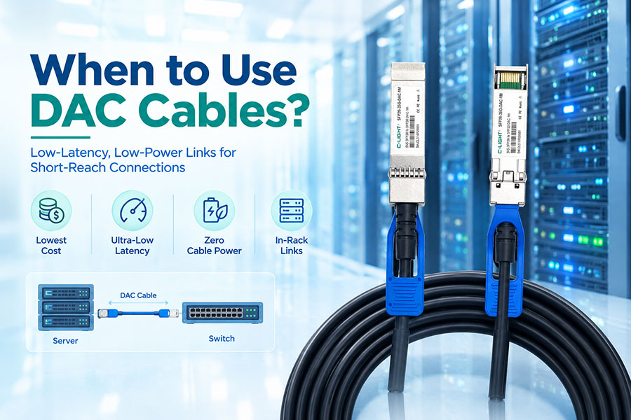
For connections under 2 meters—server-to-switch links within a rack, GPU-to-ToR connections in the same cabinet—passive DAC offers the lowest cost, lowest latency, and zero power consumption. AEC adds active electronics that increase cost and power without providing any reach benefit. DAC is designed specifically for in-rack connections where short distances and cost sensitivity are priorities.
4.2 Links Beyond 9 Meters
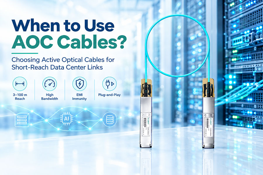
While some AEC implementations reach up to 9 meters, distances beyond this range require AOC or discrete optical modules. AOC supports reaches of 30–100 meters at 400G and above, making it the appropriate choice for cross-row connections, aggregation switch uplinks, and any link that exceeds copper's practical limits even with active signal conditioning.
4.3 Deployments Where Power Is the Absolute Priority
Passive DAC consumes essentially zero power. AEC's Retimer chips consume 1–3 W per link depending on data rate and implementation. In deployments with thousands of short links where every watt matters for PUE and cooling, DAC remains the most power-efficient option when distances permit. C-LIGHT's selection framework positions DAC for very short distance and cost-sensitive links, while AEC is reserved for medium-short distances where reach is the binding constraint.
4.4 Ultra-High-Density Deployments Where Every Millimeter Counts
While AEC cables are thinner than DAC, they are still thicker and less flexible than fiber AOC. In extreme high-density deployments where cable management space is at an absolute premium—such as liquid-cooled GPU racks with hundreds of tightly packed connections—AOC's smaller diameter and greater flexibility may be advantageous despite its higher cost.
5. AEC in the Interconnect Spectrum: DAC, ACC, AEC, AOC
AEC does not exist in isolation. It is one of four major interconnect technologies, each optimized for a specific range of distances, power budgets, and cost targets. Understanding where AEC fits in this spectrum is essential for making the right selection.
| Characteristic | DAC (Passive) | ACC (Active Copper) | AEC (Active Electrical) | AOC (Active Optical) |
|---|---|---|---|---|
| Medium | Copper | Copper | Copper | Fiber |
| Signal Processing | None | Linear equalizer (ReDriver) | Retimer (CDR + equalizer) | Optical transceivers |
| Typical Reach (400G) | ≤3 m | 3–4 m | 5–7 m | 30–100 m |
| Typical Reach (800G) | ≤2 m | 3–4 m | 5–7 m (up to 9 m) | 30–100 m |
| Power per Link (800G) | ~0 W | ~1–2 W | ~2–3 W | ~10–16 W |
| EMI Immunity | Good (shielded) | Good (shielded) | Good (shielded) | Excellent (fiber) |
| Cable Diameter | Thickest | Moderate | Thin (28–34 AWG) | Thinnest |
| Latency | Lowest | Very low | Low | Low |
| Cost | Lowest | Low | Moderate | Highest |
| Best For | In-rack<2 m=""> | In-rack 2–4 m | Cross-rack 2–7 m | Cross-row 30–100 m |
The interconnect spectrum is organized by distance. DAC dominates the shortest links where cost and power are paramount. ACC extends copper's reach modestly for in-rack connections that slightly exceed passive DAC limits. AEC takes over for cross-rack and inter-row connections where the Retimer's signal regeneration provides reliable performance over longer copper runs. AOC serves the longest reaches where copper cannot go.
C-LIGHT's product portfolio reflects this spectrum: the company offers DAC, AEC, and AOC solutions across 400G and 800G, enabling network designers to select the right technology for each link in the network.
6. AEC Reach and Power by Data Rate
AEC performance varies by data rate. As lane rates increase, the Retimer chips must operate at higher speeds, affecting reach, power consumption, and cost. Understanding these parameters is essential for planning deployments.
| Data Rate | Form Factor | Typical Reach | Typical Power (per end) | Typical Application |
|---|---|---|---|---|
| 100G | QSFP28 | 3–5 m | <1 w=""> | Server-to-ToR, storage |
| 200G | QSFP56 | 3–5 m | <1.5 w=""> | High-density ToR |
| 400G | QSFP-DD/OSFP | 5–7 m | ~1.5–2 W | Cross-rack, GPU clusters |
| 800G | QSFP-DD/OSFP | 5–7 m (up to 9 m) | ~2–3 W | AI clusters, spine-leaf |
| 1.6T | OSFP-XD/OSFP224 | 4–5 m | ~3–5 W | Next-gen AI backbone |
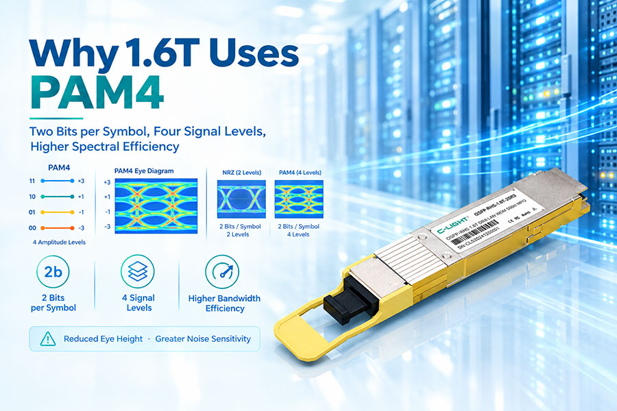
At 800G, the industry has demonstrated AEC reaching 9 meters in OCP demonstrations, bridging the DAC-AOC gap with 25–50% less power than optical solutions. At 1.6T, AEC solutions are in sample phase, with reach up to 5–6 meters and lane rates of 8×200G PAM4.
7. C-LIGHT AEC Products for AI Data Centers
C-LIGHT offers a comprehensive portfolio of AEC solutions purpose-built for AI data center and high-performance computing environments. The products support InfiniBand NDR/XDR and high-speed Ethernet protocols, ensuring stable operation in AI training and high-throughput environments.
7.1 800G AEC
C-LIGHT's 800G AEC achieves 800Gbps ultra-high-speed transmission through integrated high-performance Retimer chips, supporting distances of up to 5 meters. The product leverages Gearbox technology for 400G/800G dual-rate auto-negotiation, making it compatible with mainstream OSFP and QSFP-DD interfaces. Key functions include signal retiming, noise suppression, and equalization compensation.
The 800G AEC product family includes multiple configurations:
| Part No. | Form Factor | Data Rate | Distance | Wire Gauge |
|---|---|---|---|---|
| CLQD8-QD8AEC-5-FLT | QSFP-DD to QSFP-DD | 800G IB | 5M | 28AWG |
| CLOP8-QD8AEC-5-FTF | OSFP to QSFP-DD | 800G IB | 5M | 28AWG |
| CLOP8-OP8AEC-0.5~2.5-FIN | OSFP112 to OSFP112 | 800G IB | 0.5M–2.5M | 32AWG |
| CLOP8-OP8AEC-3~4-FIN | OSFP112 to OSFP112 | 800G IB | 3M–4M | 30AWG |
| CLOP8-OP8AEC-4.5~5-FIN | OSFP112 to OSFP112 | 800G IB | 4.5M–5M | 28AWG |
These cables are primarily deployed for GPU interconnects in AI server clusters and distributed rack cabling scenarios. The 800G AEC supports InfiniBand NDR/XDR architectures, accelerating AI training and data processing.
7.2 400G AEC
C-LIGHT's 400G AEC solutions are designed for cross-rack connections at 400G data rates. The product family supports QSFP-DD and OSFP form factors with reach up to 5–7 meters, making them suitable for ToR-to-leaf connections in 400G AI clusters and cloud data centers.
7.3 Key C-LIGHT AEC Advantages
Proven Quality Assurance: 100% tested for performance and reliability, fully compliant with industry standards.
Stable Supply Capability: Mature supply chain system supporting large-scale and consistent delivery.
Premium Quality Components: High-grade materials and advanced manufacturing ensure long-term operational stability.
Multi-Protocol Support: Compatible with both InfiniBand and Ethernet, interoperable with mainstream switches and servers.
Gearbox Technology: 400G/800G dual-rate auto-negotiation for flexible deployment.
Ultra-Low Latency: DAC/AEC architecture minimizes signal conversion, delivering near-zero latency ideal for GPU clusters and real-time computing.
8. AEC in AI Data Centers: Specific Considerations
AI workloads place unique demands on interconnect infrastructure. GPU clusters generate massive east-west traffic, training jobs are sensitive to latency and jitter, and the sheer number of links magnifies the impact of every cable decision.
8.1 GPU Cluster Interconnects
In AI clusters, GPU nodes connect to Top-of-Rack switches, and ToR switches connect to leaf and spine switches. While GPU-to-ToR connections within a rack often use DAC, the cross-rack connections between ToR and leaf switches—typically spanning 2–7 meters—are where AEC provides the optimal balance of reach, power, and signal integrity.
AEC is particularly valuable in distributed disaggregated chassis (DDC) architectures, where compute, storage, and networking components are physically separated but must be interconnected with high-bandwidth, low-latency links. AEC enables these architectures by providing the reach and reliability needed for connections between chassis within a row.
8.2 Latency Considerations
AEC introduces minimal latency compared to optical solutions. The Retimer processing adds a small amount of delay, but this remains in the nanosecond range and is significantly lower than the optical-electrical-optical conversion latency of AOC. For AI training workloads where collective communication latency matters, AEC provides near-DAC latency performance with extended reach.
8.3 Reliability and Serviceability
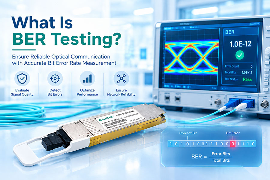
AEC integrates the signal-conditioning electronics into the cable assembly, eliminating the need for separate active components at the host port. This simplifies system design and reduces failure points. The Retimer chips are designed for high reliability, with pre-FEC BER as low as 1E-12 in optimized configurations.
C-LIGHT's AEC products are 100% tested and support commercial and industrial temperature ranges, ensuring reliable operation in demanding data center environments.
8.4 Thermal Management
AEC's lower power consumption compared to AOC translates directly to reduced thermal load. The thinner cable gauge also improves airflow in dense racks, which is important for managing thermal conditions in GPU clusters. C-LIGHT's 800G AEC uses 28AWG wire for 5-meter lengths, balancing signal performance with thermal and cable management requirements.
9. Evaluating AEC for a Specific Deployment
Selecting the right interconnect for a given link requires a structured evaluation of requirements against available options.
| Evaluation Factor | What to Confirm |
|---|---|
| Link Distance | Physical cable path length, including service loops and slack |
| Data Rate per Lane | 50G, 100G, or 200G PAM4; determines Retimer selection and reach |
| Connector Form Factor | QSFP28, QSFP-DD, OSFP, OSFP-XD; must match host ports |
| Breakout Requirement | Whether one high-speed port needs to split to multiple lower-speed ports |
| Cable Management Space | Bend radius, tray capacity, airflow path interference |
| EMI Environment | Proximity to power cables, motors, RF sources |
| Latency Budget | Whether Retimer processing latency is acceptable |
| Power Budget | Whether active cable power is acceptable at scale |
| Interoperability | Mixed-vendor deployment requirements |
| Cost per Link | Capital cost and total cost of ownership over deployment lifetime |
A disciplined evaluation compares DAC, ACC, AEC, and AOC options for each link category in the network. In most AI data center designs, the optimal architecture uses a mix: passive DAC for the shortest in-rack links, AEC for adjacent-rack and cross-rack connections that exceed passive DAC reach, and AOC for everything from cross-row links to inter-row connections up to 100 meters.
C-LIGHT's selection framework reflects this layered approach: DAC for very short distance and cost-sensitive links, AEC for medium-short distance (2–7m) where reach and signal integrity are the binding constraints, and AOC for longer fiber links where copper cannot reach.
10. The Future of AEC in Higher-Speed Networks
As Ethernet advances toward 1.6T and eventually 3.2T, AEC continues to evolve. At 800G, AEC supports reaches of 5–7 meters with power consumption of 2–3 W per end. At 1.6T, AEC solutions are in development using 8×200G PAM4 technology, targeting reach of 4–5 meters and power consumption of approximately 3–5 W per end.
The key challenges for higher-speed AEC are power consumption and thermal management. As lane rates increase to 224G per lane, the Retimer chips must operate faster, consuming more power and generating more heat. Innovations in Retimer architecture, advanced CMOS nodes, and optimized DSP algorithms are addressing these challenges.
Marvell has launched a "Golden Cable" initiative to accelerate the AEC ecosystem and hyperscaler adoption, working with cable manufacturers to optimize Retimer integration and performance. Credo, which invented the AEC category, continues to expand its ZeroFlap AEC portfolio to 1.6T speeds with telemetry, diagnostics, and fault analysis capabilities.
For the 400G, 800G, and 1.6T generations that dominate current and near-future AI data center deployments, AEC remains the most practical interconnect for the 2–7 meter range. Its combination of reach, signal integrity, power efficiency, and operational simplicity makes it indispensable for cross-rack and adjacent-rack connectivity. The key is recognizing where AEC's benefits justify its cost premium over DAC, and where AOC remains necessary for longer reaches.
11.Conclusion
AEC cables are the right choice for data center interconnects when the required distance exceeds passive DAC's reach—typically 2–3 meters at 400G and above—but does not require the full reach of optical solutions. They bridge the gap between DAC and AOC, delivering extended copper reach with Retimer-based signal conditioning that ensures reliable high-speed transmission.
The key scenarios for AEC are adjacent-rack and cross-rack connections, AI GPU cluster interconnects, mixed-vendor deployments, and environments requiring improved cable management over DAC. AEC's Retimer technology provides superior signal integrity compared to ACC's linear equalization, with lower power consumption than AOC.
When links are short enough for passive DAC, DAC remains the most cost-effective and lowest-power option. When distances exceed 7–9 meters or maximum flexibility is required, AOC or discrete optical modules become necessary. But for the 2–7 meter range that characterizes the majority of cross-rack links in modern AI data centers, AEC delivers the best balance of performance, power efficiency, and cost.
C-LIGHT's portfolio of 400G and 800G AEC solutions, with reach up to 5 meters and support for InfiniBand NDR/XDR and Ethernet protocols, provides the interconnect foundation for next-generation AI infrastructure. As AI clusters scale and network speeds advance toward 1.6T, AEC will remain an essential technology for the dense, high-bandwidth links that connect the building blocks of AI computing.
 >
>

 >
>
 >
>
 >
>
 >
>
 >
>
 >
>
 >
>