TEL:+86 132 6656 7067




A 100G ER4 optical link is designed for long-reach single-mode fiber transmission, typically up to approximately 40 km under the applicable interface specification. However, a link that works over a shorter span may fail when deployed over a longer route, even when both QSFP28 modules are detected and their diagnostic readings appear normal.
Long-distance link failures can result from insufficient optical power budget, excessive fiber and connector loss, wavelength-specific transmission effects, receiver performance limitations, FEC configuration, or interoperability problems. The actual cause must be identified by examining the complete optical link and the operating requirements of both endpoints.
1. Understanding the 100G ER4 Optical Interface
A conventional 100GBASE-ER4 QSFP28 transceiver uses four optical wavelengths in the 1300 nm band to transmit an aggregate 100 Gb/s Ethernet signal over single-mode fiber. Each optical lane carries approximately 25 Gb/s using a nominal 25.78 GBd NRZ signaling rate, consistent with the relevant 100G Ethernet lane architecture.
The four wavelengths are multiplexed onto a single transmit fiber and separated at the receiving end. The optical design therefore differs from parallel-fiber solutions such as SR4, which use multiple fibers for independent optical lanes.
| Parameter | Typical 100G ER4 Characteristics | Why It Matters |
|---|---|---|
| Module form factor | QSFP28 | Defines the module package and host interface requirements. |
| Optical fiber | Single-mode fiber (SMF) | Supports long-reach transmission with suitable optical specifications. |
| Optical channels | Four wavelengths in the 1300 nm band | Each wavelength has its own transmitter and receiver characteristics. |
| Aggregate data rate | 100 Gb/s | Requires all relevant optical and electrical lanes to operate correctly. |
| Typical specified reach | Up to approximately 40 km | Achievable reach depends on compliance with the applicable interface specification and link conditions. |
| Connector interface | Commonly duplex LC | Connector condition, fiber polarity, and insertion loss affect the optical path. |
Exact wavelength ranges, transmit power, receiver sensitivity, overload limits, and error-rate requirements depend on the specific transceiver specification. These values should be taken from the module datasheet rather than assumed from the ER4 label alone.
2. Insufficient Optical Power Budget
The optical power budget is one of the first items to evaluate when a 100G ER4 link fails near its maximum reach. The available budget is determined by the difference between the transmitter's specified optical output and the receiver's required sensitivity, subject to the limits and test conditions of the interface.
A simplified link-budget calculation is:
Estimated received power = Transmitter output power − Total optical path loss
Total path loss includes fiber attenuation, connector loss, splice loss, and other passive optical components in the path. A design margin should also be retained for expected variations and aging, according to the network engineering requirements.
For example, if the minimum specified transmitter power is -2 dBm and the receiver sensitivity is -20 dBm, the nominal difference is 18 dB. If the installed optical path consumes 16 dB, only 2 dB remains before considering the required engineering margin and other interface constraints. This is an illustrative calculation, not a universal ER4 specification.
Common causes of insufficient budget
Actual fiber length or attenuation is higher than estimated.
Connector or splice losses exceed the design allowance.
Additional patch panels or passive components introduce unplanned loss.
The transmitter operates near the low end of its permitted output range.
The receiver has limited sensitivity margin under actual operating conditions.
Compare the calculated budget with measured end-to-end loss and the exact transceiver specifications. Do not rely solely on nominal fiber attenuation or the stated maximum reach.
3. Excessive Fiber, Connector, or Splice Loss
Long-distance links often pass through multiple optical distribution frames, patch panels, connectors, and splices. Each element introduces loss, and the cumulative effect may become significant near the link's reach limit.
Dirty or damaged connectors are particularly common causes of unexpected loss. A connector can remain physically connected while its end face introduces excessive insertion loss or reflections. Incorrect patching and degraded fiber sections can also affect link performance.
Recommended checks
Inspect and clean connectors using approved fiber-cleaning procedures.
Verify the fiber route, patch-panel connections, and connector type.
Review insertion-loss measurements against the link design.
Use an optical time-domain reflectometer (OTDR) where appropriate to investigate suspected fiber events, breaks, or abnormal splice loss.
Confirm that the measured route length and passive-component loss match the network documentation.
An OTDR trace helps locate events along the fiber, but it does not replace an end-to-end insertion-loss test. Both measurements may be useful when a long-reach link has insufficient margin.
4. Wavelength-Specific Performance and Dispersion
ER4 uses four optical wavelengths rather than a single optical carrier. Each wavelength travels through the same fiber route but can exhibit different transmitter power, receiver sensitivity, and optical-path behavior.
At long distances, chromatic dispersion can affect signal quality. The amount of impact depends on the fiber characteristics, wavelength, transmitter design, and the applicable transmission specification. A compliant 100GBASE-ER4 link is designed to operate within defined channel requirements, but mismatched components or noncompliant optics may not deliver the expected performance.
When the platform exposes per-lane information, compare the relevant optical diagnostics and error counters rather than relying only on aggregate readings. A single weak optical channel may contribute to link failure even if the other channels appear healthy.
Useful checks include:
Confirm the module is genuinely specified for the required 100G ER4 interface and reach.
Compare each available transmitter and receiver channel measurement with the datasheet limits.
Review lane-level error statistics where the equipment exposes them.
Verify that the installed fiber and both endpoint modules meet the intended optical interface requirements.
5. Receiver Sensitivity and Excessive Receive Power
A receiver must operate within its specified input range. If the received optical signal is too weak, the receiver may not meet the required error-rate performance. Conversely, a signal above the receiver's specified overload limit can also prevent correct operation.
| Observed Condition | Potential Effect | Recommended Action |
|---|---|---|
| Rx power below the specified sensitivity limit | Insufficient signal level and possible high BER or link loss. | Measure path loss, inspect connectors, and verify transmitter output. |
| Rx power close to the sensitivity threshold | Limited operating margin and possible instability under changing conditions. | Reduce avoidable loss and verify the design margin. |
| Rx power above the overload limit | Receiver may not meet the specified performance requirements. | Check the optical architecture and attenuation requirements in the datasheet. |
| Rx power appears normal but errors remain high | Possible signal-quality, wavelength, compatibility, or electrical-interface problem. | Review BER, FEC, module alarms, and endpoint compatibility. |
DOM/DDM readings are useful for initial diagnosis, but they may not identify every optical impairment. When readings are close to a limit or inconsistent with the observed behavior, use appropriate calibrated test equipment and follow the module manufacturer's measurement guidance.
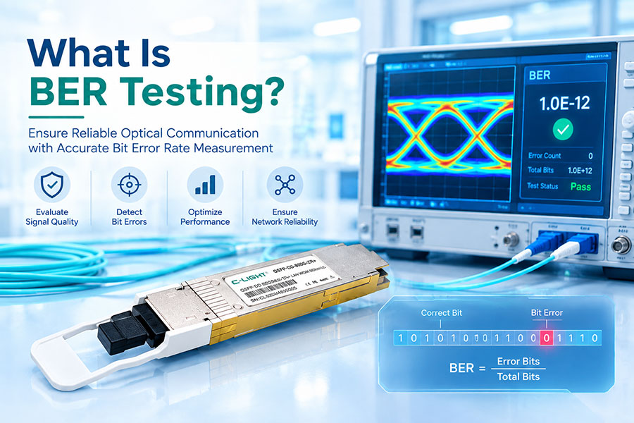
6. FEC Configuration and BER Errors
Forward error correction (FEC) and bit error rate (BER) are important indicators when a long-reach link shows rising errors or repeated link drops. The expected FEC behavior depends on the exact Ethernet PHY and interface specification.
High error counts may indicate that the received signal has insufficient quality margin. Potential causes include excessive attenuation, transmitter or receiver problems, optical-channel impairments, host electrical signal issues, or incompatible configuration.
| Diagnostic Result | Possible Meaning | Next Step |
|---|---|---|
| Link down with no obvious optical alarm | Could involve configuration, lane initialization, compatibility, or an optical impairment not reported by the module. | Check both endpoint logs, port state, PHY status, and optical diagnostics. |
| Corrected FEC errors increase over time | Errors are being corrected; the rate and trend determine whether the link has adequate margin. | Track counter growth and correlate it with BER and signal measurements. |
| Uncorrectable FEC errors occur | The error level may exceed the correction capability or indicate a PHY problem. | Verify FEC requirements, optical quality, and host interface status. |
| Errors persist with stable Rx power | Power level alone may not explain the impairment. | Investigate signal quality, wavelength-specific behavior, module compatibility, and electrical diagnostics. |
Do not disable or change FEC simply to make the link come up. Confirm the required configuration from the applicable Ethernet interface and equipment documentation before making changes. A configuration that is unsupported or inconsistent at the two endpoints may introduce additional problems.
7. Module Compatibility and Equipment Configuration
A 100G QSFP28 ER4 module may be detected by a switch without successfully establishing a stable link. Host support, firmware, port settings, module coding, and interoperability can affect operation independently of the optical budget.
Confirm that both devices support the specific 100G ER4 optical interface.
Check the configured port speed, interface mode, and relevant FEC requirements.
Review module alarms, platform logs, and firmware compatibility information.
Verify that the modules at both ends use compatible optical specifications.
Check whether the host port has reported electrical lane, PCS, or initialization errors.
For multi-vendor links, do not assume that a matching form factor and nominal data rate guarantee interoperability. Check the supported module information for each platform and validate the actual optical and host-interface requirements.
8. Step-by-Step Troubleshooting Procedure
The following sequence helps isolate the cause without replacing multiple components unnecessarily.
Step 1: Record the link state
Check the administrative state, operational state, module identification, alarms, and recent link events at both endpoints. Establish whether the failure is continuous, intermittent, or associated with a particular operating condition.
Step 2: Collect optical diagnostics
Record Tx power, Rx power, temperature, voltage, and available channel-level measurements from both transceivers. Compare each value with the applicable datasheet limits.
Step 3: Verify the link budget
Calculate the expected received power using transmitter output, measured path loss, and the required margin. If the measured loss is higher than expected, investigate connectors, patch panels, splices, and the fiber route.
Step 4: Inspect the physical path
Check connector cleanliness, fiber type, patching, and the duplex connection. Use suitable optical test equipment when necessary to measure insertion loss or locate abnormal events.
Step 5: Review BER and FEC information
Record the baseline counters before clearing them. Observe corrected and uncorrectable errors over a defined interval and correlate their growth with optical power, temperature, and link events.
Step 6: Validate configuration and compatibility
Confirm speed, FEC, platform support, firmware, and relevant host interface status. Make changes only in accordance with the supported configuration.
Step 7: Perform controlled substitution
If the issue remains unresolved, test a known-good compatible transceiver or fiber path, changing one variable at a time. This helps distinguish a module problem from a cabling, port, or configuration issue.
9. Troubleshooting Checklist
| Check Item | What to Verify | Diagnostic Goal |
|---|---|---|
| Transceiver specification | 100G ER4 support, wavelength range, reach, and host compatibility. | Rule out an interface mismatch. |
| Tx/Rx power | Both endpoint readings and the applicable operating limits. | Identify weak or excessive optical input. |
| Fiber path | Route length, connector condition, splice loss, and passive components. | Find excessive insertion loss. |
| Channel performance | Available lane-level readings and error counters. | Identify a channel-specific impairment. |
| FEC and BER | Required FEC mode, corrected errors, uncorrectable errors, and BER. | Assess signal quality and decoding performance. |
| Platform configuration | Port speed, firmware, alarms, and host interface status. | Identify configuration or interoperability issues. |
| Substitution test | Known-good supported module or fiber path. | Isolate the suspected component. |
10. Frequently Asked Questions
Q1. What is the typical reach of a 100G ER4 optical transceiver?
Answer: A standards-based 100GBASE-ER4 interface is generally designed for up to approximately 40 km over single-mode fiber under its specified operating conditions. The achievable reach of a particular product depends on its documented specification and the installed link.
Q2. Can a 100G ER4 link fail even when Rx power is within range?
Answer: Yes. Receive power is only one indicator. High BER, wavelength-specific signal degradation, host electrical problems, incompatible configurations, or other optical impairments can still prevent reliable operation.
Q3. Can dirty LC connectors cause a long-distance ER4 link failure?
Answer: Yes. Contamination can increase insertion loss or reflections and reduce the available link margin. Inspect and clean connectors using approved procedures before reconnecting them.
Q4. Why does the link work over 10 km but fail over 35 km?
Answer: The longer route may introduce enough additional fiber and connector loss to reduce the received signal margin. Check the measured end-to-end loss, receiver sensitivity, required design margin, and any wavelength-specific or configuration issues.
Q5. Does a 100G ER4 link require FEC?
Answer: FEC requirements depend on the applicable Ethernet interface and implementation. Verify the required mode and configuration for the exact transceiver and host platform rather than assuming all 100G ER4 products use the same settings.
Q6. Should a transceiver be replaced immediately when the link fails?
Answer: Not necessarily. Check optical diagnostics, fiber loss, connector condition, configuration, and error counters first. A controlled substitution with a known-good compatible module can help confirm whether the transceiver itself is responsible.
11. Conclusion
A 100G ER4 link that fails at long distance may be affected by insufficient optical power budget, excessive fiber loss, receiver limitations, wavelength-specific signal degradation, FEC or BER issues, or equipment compatibility. Similar symptoms can arise from different causes, so diagnosis should combine optical measurements, error statistics, and host-interface information.
Before replacing a transceiver, verify the actual link loss, inspect the optical path, compare diagnostics against the product specifications, and confirm the configuration at both ends. A systematic approach helps identify the true failure point and improves long-distance link reliability.
100G Optical Transceiver Solutions
Review 100G QSFP28 optical transceivers for single-mode fiber networks, including long-reach applications and different optical interface requirements.
Contact C-LIGHT >
>

 >
>
 >
>
 >
>
 >
>
 >
>
 >
>
 >
>