TEL:+86 132 6656 7067




Optical power decreases as light travels through fiber because part of the transmitted energy is absorbed, scattered, or lost at connection points and other optical components. In long-distance links, these losses accumulate across the transmission path, reducing the optical power that reaches the receiving transceiver.
Low received power can reduce the receiver's operating margin and contribute to link instability, high bit error rate (BER), or loss of connectivity. Understanding the sources of optical attenuation is essential for link-budget planning, transceiver selection, and troubleshooting long-distance fiber connections.
1. Fiber Attenuation Accumulates with Distance
Fiber attenuation is the reduction in optical signal power as light propagates through the fiber. It is commonly expressed in decibels per kilometer (dB/km). Even when the fiber is correctly installed and undamaged, its attenuation causes received optical power to decrease as transmission distance increases.
Two important mechanisms contribute to attenuation:
Material absorption: Optical energy is absorbed by the glass and by impurities within the fiber, converting part of the energy into heat.
Scattering: Small variations in the fiber's material and structure scatter light away from the guided optical mode. Rayleigh scattering is a major source of intrinsic attenuation in silica fiber.
Fiber attenuation depends on wavelength and fiber type. Modern single-mode fiber generally has low attenuation around the 1310 nm and 1550 nm transmission regions, although the actual value depends on the fiber specification and installed cable conditions.
| Wavelength Region | Typical Application | Attenuation Considerations |
|---|---|---|
| 850 nm | Short-reach multimode links | Commonly used with multimode fiber in data centers. Fiber attenuation and modal bandwidth both affect the supported link distance. |
| 1310 nm | Single-mode Ethernet and access links | Low-loss transmission region commonly used for short- and medium-reach single-mode links. |
| 1550 nm | Long-distance transmission and DWDM systems | Offers low fiber attenuation and supports optical amplification in suitable systems, but dispersion and nonlinear effects still require consideration. |
These wavelength regions are general examples, not interchangeable operating specifications. The supported wavelength and transmission distance must match the transceiver, fiber, and optical system design.
2. Connector and Splice Losses Add to Fiber Attenuation
Fiber attenuation is only one part of the total link loss. Long-distance routes may contain patch panels, adapters, intermediate distribution frames, and fusion or mechanical splices. Each connection or splice can introduce additional insertion loss.
Connector insertion loss: Misalignment, end-face contamination, air gaps, or poor connector condition can reduce transmitted power.
Splice loss: Core misalignment, poor fusion splicing, or differences between fiber characteristics can introduce localized loss.
Passive component loss: Splitters, WDM filters, multiplexers, demultiplexers, and other components consume part of the optical power budget.
A long link with many intermediate connections can therefore have substantially more loss than a continuous fiber span of the same length. Connector quality and splice workmanship are especially important when the optical budget is limited.
3. Fiber Bending and Physical Damage Increase Loss
Fiber routing can affect optical power even when the cable is not visibly broken. Bending changes the conditions under which light remains confined within the fiber, allowing some optical energy to escape from the guided mode.
Two common types of bending loss are:
Macrobending: Loss caused by a bend with a relatively large, visible radius, such as fiber routed around a corner too tightly.
Microbending: Small local deformations caused by pressure, cable construction, installation stress, or external forces.
Crushed cables, excessive pulling tension, damaged patch cords, and poorly managed fiber trays can also increase attenuation. Follow the cable manufacturer's minimum bend-radius requirements and inspect the complete route when measured loss exceeds expectations.
4. Calculate the Total Optical Link Loss
The total optical loss is the sum of fiber attenuation and the insertion losses of components along the optical path. A basic link-loss estimate can be calculated using the following formula:
Consider an illustrative 40 km single-mode link with the following assumptions:
| Parameter | Assumed Value |
|---|---|
| Fiber length | 40 km |
| Fiber attenuation | 0.25 dB/km |
| Fiber attenuation loss | 40 × 0.25 = 10 dB |
| Combined connector and splice loss | 2 dB |
| Estimated total link loss | 12 dB |
In this example, the receiving end receives approximately 12 dB less optical power than the transmitting end, assuming no optical amplification or other active gain along the path. If the transmitter output is -2 dBm, the estimated received power is -14 dBm.
5. Why Long-Distance Links Have Less Optical Power Margin
As the fiber route becomes longer, fiber attenuation consumes more of the available optical power budget. The remaining margin must accommodate connector and splice losses, component variation, aging, repairs, and other installation uncertainties.
The available optical power budget is commonly estimated as:
For example, a transceiver with a minimum TX power of -2 dBm and receiver sensitivity of -18 dBm has a nominal power budget of 16 dB. This budget must cover the complete optical path, not just fiber attenuation.
Receiver sensitivity is not the only design limit. The received signal must also remain below the receiver's maximum input power, and the system must satisfy the relevant reach, dispersion, BER, and FEC requirements. A link that meets the basic power calculation may still fail if other transmission constraints are violated.
6. Wavelength and Fiber Type Affect Transmission Performance
Optical power loss depends on the wavelength and fiber used. A transceiver designed for one fiber type or wavelength cannot automatically be expected to achieve the same distance over another.
Single-mode fiber: Commonly used for longer distances because it supports a single spatial propagation mode under its specified operating conditions and is well suited to low-attenuation transmission.
Multimode fiber: Commonly used for short-reach links. Attenuation, modal bandwidth, launch conditions, and transceiver design affect the achievable distance.
Wavelength-specific transceivers: Their supported fiber types, reach, and optical limits must match the installed link.
For example, an 850 nm SR transceiver designed for multimode fiber should not be treated as a substitute for a 1310 nm single-mode transceiver on a long single-mode route. Matching the connector alone does not establish optical compatibility.
7. Optical Power Loss in WDM and Amplified Systems
Long-distance systems may use CWDM, DWDM, optical amplifiers, or intermediate optical distribution equipment. These components introduce additional considerations beyond the attenuation of the fiber itself.
In WDM systems, multiplexers and demultiplexers introduce insertion loss. Channel filters and other passive devices also contribute to the end-to-end power budget. Individual wavelengths may experience different loss depending on the components and channel plan.
Optical amplifiers can compensate for transmission loss, but they do not eliminate all signal-quality limitations. Amplifiers introduce noise, and the resulting optical signal-to-noise ratio (OSNR), dispersion, nonlinear effects, and receiver performance can constrain transmission even when measured optical power is adequate.
When troubleshooting an amplified or WDM link, measure power at relevant points in the optical path and compare each measurement with the system design. Avoid interpreting a single end-to-end power reading as a complete indication of signal quality.
8. How to Troubleshoot Unexpected Optical Power Decrease
If the received optical power is lower than expected, use a systematic approach to distinguish normal fiber attenuation from an installation fault or equipment problem.
Read the transceiver diagnostics: Record TX power, RX power, temperature, voltage, and any active alarms using DDM/DOM or platform diagnostics.
Compare both ends: Check the remote transmitter output and local receiver input. Confirm that the measurements refer to the same optical path and are taken under comparable conditions.
Calculate expected loss: Estimate fiber attenuation and add connector, splice, and passive component losses. Compare the result with the measured loss.
Inspect and clean connectors: Check patch cords, adapters, and intermediate connections using approved inspection and cleaning procedures.
Check fiber routing: Look for excessive bends, crushed cables, pulling damage, and poor cable management.
Verify optical compatibility: Confirm wavelength, fiber type, connector interface, supported distance, and passive component specifications.
Use test equipment when needed: Measure optical power independently and use an OTDR, where appropriate, to investigate localized loss along the route.
Recheck link performance: After correcting the suspected issue, confirm RX power, error counters, and link stability.
DDM/DOM readings provide a convenient starting point, but an independent power meter can help verify unexpected readings. An OTDR can identify the location of certain fiber events, although its results must be interpreted according to the test setup and fiber characteristics.
9. Common Symptoms and Their Likely Causes
| Observed Condition | Potential Cause | Recommended Action |
|---|---|---|
| RX power decreases gradually with distance | Normal fiber attenuation | Verify the link budget and supported transmission reach. |
| RX power is lower than the calculated value | Additional connector, splice, or passive component loss | Inspect the optical path and measure insertion loss. |
| Power changes when the cable is moved | Excessive bending, cable damage, or an unstable connection | Inspect routing and substitute a known-good patch cord. |
| One direction has low RX power | Weak transmitter, damaged fiber strand, or direction-specific loss | Compare TX and RX readings at both endpoints. |
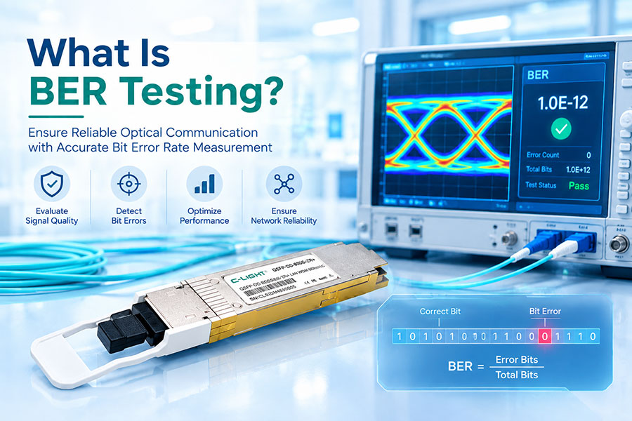
| RX power is normal but BER is high | Dispersion, noise, reflections, or electrical signal integrity problems | Check BER, FEC counters, lane statistics, and signal quality. |
| RX power exceeds the specified maximum | Excessive optical input for the receiver | Verify the module's maximum input rating and the link design. |
10.Frequently Asked Questions
In an unamplified passive fiber path, optical power generally decreases with distance because of fiber attenuation and accumulated component loss. Systems with optical amplifiers can restore power levels at intermediate points, but they introduce other design constraints.
It depends on the fiber type, wavelength, and applicable specification. Modern single-mode fiber often has attenuation around 0.2–0.35 dB/km in common 1310 nm and 1550 nm operating regions, depending on the fiber and specification. Use the actual cable datasheet and wavelength-specific limits for engineering calculations.
Yes. Contamination can increase insertion loss and reflections, reducing the power delivered to the receiver. Connector inspection and appropriate cleaning are important steps in optical link maintenance.
A short link should normally have relatively low fiber attenuation, so unexpectedly low RX power may indicate dirty connectors, a damaged patch cord, incorrect routing, a weak transmitter, a faulty receiver reading, or loss from an intermediate component.
It may continue operating if the received power remains within the receiver's supported range and sufficient signal-quality margin is available. However, reduced margin can make the link more vulnerable to errors and environmental variation. The module's specified operating limits and the system requirements determine whether the power level is acceptable.
No. Optical power is only one performance parameter. Dispersion, OSNR, reflections, nonlinear effects, transceiver compatibility, BER, and FEC performance may still limit the link. A complete assessment should consider the relevant optical and digital transmission specifications.
11.Conclusion
Optical power decreases over long-distance fiber links because of fiber attenuation and accumulated losses from connectors, splices, bends, and passive components. Wavelength, fiber type, installation quality, and optical system architecture determine how much power reaches the receiver.
Accurate link-budget calculations, TX/RX power monitoring, connector inspection, and optical loss testing help identify whether a power decrease is expected or caused by a fault. For long-distance deployments, maintaining adequate optical margin and verifying signal quality are essential for reliable transmission.
Need help selecting optical transceivers for your link distance?
Review transmission reach, wavelength, fiber type, optical budget, and host compatibility before deployment.
Contact C-LIGHT >
>

 >
>
 >
>
 >
>
 >
>
 >
>
 >
>
 >
>