TEL:+86 132 6656 7067




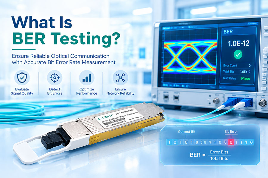
Bit Error Rate (BER) is a key indicator of digital signal quality in optical communication systems. A high BER means that a larger proportion of transmitted bits are received incorrectly, potentially causing packet loss, retransmissions, degraded throughput, link instability, or complete service interruption.
High BER can originate from insufficient optical power, excessive noise, signal distortion, fiber defects, transceiver problems, electrical channel impairments, or incorrect link configuration. In high-speed Ethernet and InfiniBand networks, the underlying cause may also involve signal integrity, clock and data recovery, lane alignment, or Forward Error Correction (FEC) performance.
1. What Is Bit Error Rate?
BER is the ratio of incorrectly received bits to the total number of bits evaluated during a measurement period. It is a dimensionless value commonly expressed in scientific notation.
| Measured BER | Interpretation |
|---|---|
| 1 × 10-12 | Approximately one erroneous bit per trillion received bits on average. |
| 1 × 10⁻⁹ | A higher error rate that may exceed the acceptable limit for a particular interface or test requirement. |
| 1 × 10⁻⁶ | A substantially elevated error rate that generally indicates serious signal-quality problems in high-speed optical links. |
Acceptable BER depends on the interface standard, modulation format, measurement point, and whether FEC is enabled. A pre-FEC BER value cannot be interpreted in the same way as a post-FEC BER value. Always evaluate the reading against the applicable specification and equipment requirements.
2. Insufficient Optical Receive Power
Low received optical power is a common cause of high BER. When the optical signal approaches or falls below the receiver's operating threshold, the receiver has less margin to distinguish the transmitted data from noise. This can increase decision errors, particularly when the link is already affected by dispersion or other signal impairments.
Potential causes include:
Excessive fiber attenuation over the installed link distance.
Dirty, damaged, or poorly seated optical connectors.
Excessive insertion loss from patch panels, adapters, splices, or passive optical components.
Incorrect fiber type or an unsuitable optical transceiver for the required reach.
Degraded transmitter output or a receiver operating near its sensitivity limit.
Check the local transceiver's RX power and the remote transceiver's TX power using DDM/DOM readings where available. Compare measured values with the module specifications and calculate the total link loss. A normal-looking RX power reading does not automatically rule out signal-quality problems, because dispersion, reflections, and noise can cause high BER even when received power is within the specified range.
3. Excessive Noise and Poor Optical Signal Quality
Optical receivers must distinguish the intended signal from noise. When noise becomes significant relative to the signal, the receiver is more likely to make incorrect bit decisions.
Noise and signal-quality degradation may be associated with:
Transmitter noise or degraded laser performance.
Optical amplifiers introducing amplified spontaneous emission (ASE) noise in amplified links.
Reflections caused by poor connector interfaces or unsuitable optical components.
Electrical noise in the host board, power supply, or high-speed signal path.
Receiver performance limitations under adverse operating conditions.
For coherent systems and amplified long-haul links, optical signal-to-noise ratio (OSNR) can be an important diagnostic parameter. For direct-detection links, receiver signal quality, optical power, eye opening, and waveform distortion may be more directly relevant. The appropriate measurement depends on the transceiver architecture and link design.
4. Chromatic Dispersion and Other Signal Distortion
Chromatic dispersion causes different wavelength components of an optical signal to propagate at different speeds through fiber. The resulting pulse spreading can cause adjacent symbols to overlap, increasing inter-symbol interference and BER.
Other sources of signal distortion include:
Fiber length exceeding the transceiver's specified transmission reach.
Dispersion limitations in high-speed single-mode fiber links.
Modal dispersion in multimode fiber when the optical module, fiber type, or link length is unsuitable.
Bandwidth limitations or reflections in the optical path.
Nonlinear effects in certain high-power, long-distance optical transmission systems.
Different transceiver types have different reach and dispersion characteristics. A module that supports a particular distance under specified conditions may not maintain the same performance with different fiber characteristics, passive components, or operating margins. Confirm the supported reach and fiber requirements before deployment.
5. Dirty Connectors, Fiber Bends, and Physical Damage
Physical problems in the fiber path can introduce insertion loss, reflections, or localized signal degradation. These issues may produce intermittent BER spikes rather than a continuously high error rate.
| Physical Issue | Possible Effect | Recommended Check |
|---|---|---|
| Contaminated connector end face | Increased insertion loss or reflections | Inspect and clean using approved fiber-cleaning procedures. |
| Excessive fiber bending | Additional attenuation and unstable receive power | Check bend radius and cable routing. |
| Damaged patch cord | High loss, intermittent signal, or complete link failure | Substitute a known-good cable and retest. |
| Incorrect fiber polarity | Incorrect lane mapping or failure to establish the intended link | Verify Tx-to-Rx connectivity and lane mapping. |
| Incorrect MPO/MTP alignment or mapping | Lane errors, missing lanes, or link instability | Verify connector type, polarity method, and fiber positions. |
Inspecting, cleaning, and retesting the optical path should be part of the initial troubleshooting process. For suspected high loss or physical damage, an optical power meter and, where appropriate, an OTDR can help identify the location and nature of the problem.
6. Optical Transceiver or Host Electrical Problems
High BER is not always caused by the optical fiber. The electrical interface between a switch, NIC, or other host device and the optical transceiver can also degrade signal quality.
Possible causes include:
Transmitter or receiver circuitry operating outside its expected performance range.
Electrical channel loss, crosstalk, reflections, or impedance discontinuities on the host board.
Inadequate signal conditioning or equalization for the channel.
Clock and Data Recovery (CDR) instability or poor clock recovery margin.
Thermal conditions affecting transceiver performance.
Module interoperability issues involving host electrical requirements or firmware support.
For high-speed 100G, 400G, 800G, and 1.6T interfaces, multiple electrical lanes operate at high symbol rates. A link can report acceptable optical power while still experiencing lane-specific errors caused by electrical signal integrity or receiver recovery limitations.
Compare lane-level error counters, module diagnostics, host interface statistics, and temperature readings. Where permitted, substitute a known-good compatible transceiver or cable and test another host port to determine whether the problem follows the module, the channel, or the host interface.
7. Incorrect FEC Configuration or Excessive Correctable Errors
Forward Error Correction adds redundancy to transmitted data so that the receiver can detect and correct a defined range of errors. Depending on the interface, FEC may be required or expected for normal operation.
High BER-related symptoms can occur when:
The configured FEC mode does not match the requirements of the interface or link partner.
The physical link has a high pre-FEC BER, causing the FEC engine to work near or beyond its correction capability.
Uncorrectable codewords or FEC-related error counters increase over time.
The two ends use incompatible interface modes or lane configurations.
Physical signal quality is insufficient despite FEC being enabled.
FEC can correct errors within its capability, but it cannot compensate indefinitely for severe optical or electrical impairments. A link may remain operational while corrected-error counters increase, then become unstable if the error rate exceeds the correction capability.
8. Wavelength, Fiber Type, and Link Configuration Mismatch
Incorrect optical components or link settings can reduce signal quality or prevent a stable link from forming. A transceiver may fit the port mechanically but still be unsuitable for the actual optical path or protocol.
Verify the following:
Wavelength compatibility between the transmitting and receiving ends.
Single-mode or multimode fiber selection and supported transmission distance.
Optical connector type and the use of appropriate patch cords.
Compatibility of BiDi transceivers, which use complementary transmit and receive wavelengths.
Correct lane mapping and breakout configuration for parallel-optics links.
Supported speed, interface mode, FEC, and host-device compatibility.
For WDM systems, confirm that the selected wavelengths match the channel plan and optical components. For parallel links such as SR4 or DR4, check the MPO/MTP fiber mapping and lane status rather than relying only on a single aggregate power value.
9. Temperature and Power Supply Instability
Transceiver temperature and supply voltage can influence laser operation, receiver circuitry, and high-speed signal processing. Excessive temperature may reduce operating margin or trigger protective behavior, while unstable supply voltage can affect module performance.
Review module temperature, supply voltage, laser bias current, TX power, and RX power through DDM/DOM or the platform's diagnostic interface. Compare readings with the specific module's operating limits rather than applying one universal threshold.
Also inspect rack airflow, neighboring high-power modules, heatsink contact, port density, and the host's cooling conditions. If BER rises mainly during periods of high utilization or elevated temperature, correlate the error counters with environmental and traffic data to identify a possible relationship.
10. How to Troubleshoot High BER Step by Step
A structured troubleshooting sequence helps isolate whether the fault originates in the optical path, the transceiver, the host electrical channel, or the link configuration.
Confirm the measurement. Identify whether the reported value is pre-FEC BER, post-FEC BER, a physical-layer error counter, or a higher-layer packet error metric. Check the measurement interval and test conditions.
Review link status and counters. Check interface logs, CRC or symbol errors where applicable, lane-level statistics, FEC corrected errors, and uncorrectable errors. Record the counters before and after a defined test interval.
Check TX and RX optical power. Compare readings at both ends against the module specifications. Look for abnormal power levels or significant differences between lanes.
Inspect the fiber path. Verify connector cleanliness, cable condition, bend radius, polarity, patch-panel connections, and passive optical components.
Verify configuration. Confirm speed, wavelength, fiber type, FEC mode, breakout mapping, and link-partner compatibility.
Test with known-good components. Replace one component at a time, such as the patch cord or transceiver, and observe whether the fault follows the component or remains with the port.
Check electrical and thermal conditions. Review host port diagnostics, lane errors, module temperature, supply voltage, and airflow.
Run a controlled BER test. Use a suitable BERT or platform-supported test method under defined conditions. For field links, correlate results with actual traffic and platform counters.
Change one variable at a time and preserve the original counter readings. This makes it easier to determine whether a corrective action actually improves the link instead of merely coinciding with a temporary reduction in errors.
11. Common Symptoms and Their Likely Causes
| Observed Symptom | Potential Cause | Priority Check |
|---|---|---|
| High BER with low RX power | Excessive link loss, dirty connectors, weak transmitter | Measure optical power and inspect the fiber path. |
| High BER with normal RX power | Dispersion, noise, reflections, electrical signal integrity | Check link quality, lane counters, and transmitter/receiver performance. |
| Increasing FEC corrected errors | Degrading signal margin or a noisy physical channel | Track pre-FEC BER and the corrected-error trend. |
| Uncorrectable FEC errors or link drops | Errors beyond FEC capability, incompatible configuration, or severe signal impairment | Verify FEC mode and investigate the physical channel. |
| Errors concentrated on one lane | Lane-specific optical, electrical, or connector problem | Compare per-lane power and error statistics. |
| BER rises as temperature increases | Thermal or operating-margin issue | Correlate temperature, voltage, and BER over time. |
| Intermittent BER spikes | Loose connections, damaged fiber, unstable signal recovery, or transient interference | Inspect connections and correlate logs with the event time. |
12. Frequently Asked Questions
There is no single threshold for every optical interface. The acceptable value depends on the standard, modulation format, FEC scheme, and whether the measurement is taken before or after FEC. Compare the measured BER with the applicable interface specification.
Yes. Adequate receive power does not guarantee a clean signal. Dispersion, noise, reflections, electrical channel impairments, clock recovery problems, or lane-specific faults can increase BER even when RX power is within the specified range.
No. FEC corrects errors only within its defined capability and must match the requirements of the link. If the physical signal is too degraded, uncorrectable errors and link instability can remain even with FEC enabled.
Yes, but the transceiver should not be assumed faulty before checking the fiber path, configuration, and host interface. Substitution with a known-good compatible module can help isolate the cause.
Common tools include switch or NIC diagnostics, transceiver DDM/DOM monitoring, optical power meters, inspection and cleaning tools, OTDRs for suitable fiber investigations, and Bit Error Rate Testers (BERTs). The required tools depend on the link type and suspected fault.
High-speed links have tighter signal-integrity margins and may use multiple lanes, advanced modulation, DSP, and FEC. Lane-specific signal degradation, electrical channel loss, optical impairments, or incorrect configuration can cause elevated errors. Check per-lane diagnostics and FEC statistics where available.
Conclusion
High BER in optical communication is a signal-quality problem that can originate in the optical path, transceiver, host electrical channel, or link configuration. Low receive power is one possible cause, but normal optical power does not rule out dispersion, noise, reflections, electrical impairments, or FEC-related problems.
Effective diagnosis combines BER measurements with TX/RX power readings, lane-level statistics, FEC counters, temperature and voltage data, physical fiber inspection, and controlled component substitution. Identifying the underlying cause is more reliable than replacing optical modules based on BER alone.
Need optical connectivity for your network?
Review transceiver specifications, link requirements, and compatibility before deployment.
Contact C-LIGHT >
>

 >
>
 >
>
 >
>
 >
>
 >
>
 >
>
 >
>