TEL:+86 132 6656 7067




An optical transceiver link can fail to establish, remain unstable, or experience errors even when both modules are installed correctly. Common causes include insufficient optical power, dirty fiber connectors, incorrect polarity, incompatible transceivers, mismatched interface settings, and electrical signal integrity problems.
Effective troubleshooting starts with the actual link symptoms and available diagnostics. Checking interface status, transceiver alarms, transmit and receive power, lane statistics, and FEC counters can help isolate the problem before replacing components.
1. Identify the Link Failure Symptom
Determine whether the connection is completely down, intermittently disconnecting, or operational with errors. Different symptoms point toward different fault categories.
| Observed Symptom | Potential Causes | Initial Check |
|---|---|---|
| Link remains down | No optical signal, incorrect fiber routing, incompatible module, unsupported speed, or configuration mismatch | Check interface status, module recognition, and RX power. |
| Link flaps intermittently | Unstable optical power, loose connection, thermal issue, or signal integrity problem | Review event logs, temperature, and power trends. |
| Link is up but traffic errors increase | High BER, FEC errors, marginal signal quality, or electrical channel impairment | Inspect error counters and lane-level statistics. |
| One direction fails | Faulty transmitter, receiver, fiber strand, or incorrect Tx/Rx routing | Compare TX power at one end with RX power at the opposite end. |
| Only certain lanes fail | Lane-specific optical, electrical, connector, or mapping issue | Check per-lane diagnostics and fiber mapping. |
| Link works at a lower speed but fails at the target speed | Insufficient channel bandwidth, incompatible settings, or limited signal margin | Verify supported rates, host channel requirements, and FEC configuration. |
2. Check Interface Status and Transceiver Recognition
Start with the switch, router, server NIC, or other host device. Confirm that the port is administratively enabled, the physical link state is correct, and the transceiver is recognized by the platform.
Depending on the device operating system, useful diagnostics may include:
Interface administrative and operational states.
Negotiated or configured link speed and interface mode.
Transceiver vendor, part number, serial number, and supported capabilities.
Module alarms, warnings, and diagnostic monitoring status.
Interface logs, link transitions, and error counter history.
If the module is not detected, check whether the host supports the module type and speed. Confirm the port's form-factor requirements, firmware support, and vendor compatibility policy. A physically compatible module is not necessarily supported by every host platform.
3. Measure TX and RX Optical Power
Transmit power (TX) indicates the optical output of a module, while receive power (RX) indicates the optical signal reaching the receiver. These values are among the most useful first checks for a fiber link.
TX power: Compare the reading with the transmitter's specified operating range.
RX power: Confirm that the reading falls within the receiver's specified sensitivity and maximum input range.
Power alarms: Check whether the module reports low-power or high-power warnings.
Lane power: For parallel-optics modules, review individual lane readings when supported.
For a simple point-to-point link, estimated optical path loss can be calculated as follows:
For example, if the remote transmitter reports -2 dBm and the local receiver reports -7 dBm, the estimated loss is 5 dB, assuming the measurements are accurate and refer to the same optical path and operating conditions.
Compare the estimated loss with the expected fiber attenuation and the loss budget for the link. For multi-lane links, wavelength-division systems, or links containing amplifiers and other active devices, interpretation may require additional information.
DDM/DOM readings are useful for initial diagnosis, but they are not a substitute for an independent optical power meter when readings are questionable or require verification.
4. Inspect Fiber Connectors and Cabling
Contaminated connectors, damaged patch cords, excessive bending, and poor connections can introduce additional loss or reflections. These faults may cause low RX power, intermittent link drops, or high error rates.
Check the complete optical path, including:
Transceiver optical receptacles and fiber connector end faces.
Patch cords, adapters, patch panels, and intermediate connections.
Fiber routing and bend radius.
Connector type and polish compatibility.
Signs of cable damage or unstable physical connections.
Use an appropriate fiber inspection tool and approved cleaning equipment. Inspect and clean connectors before reconnecting them, and avoid touching or exposing connector end faces to contamination. Replace a suspect patch cord with a known-good cable when necessary.
If the link still exhibits excessive loss, an optical power meter can quantify the received signal. An OTDR may help locate faults such as breaks, bends, or high-loss events along suitable fiber links.
5. Verify Fiber Polarity, Wavelength, and Lane Mapping
Correct optical routing is essential for reliable transmission. The transmitter at one end must connect to the intended receiver at the opposite end. Incorrect polarity or lane mapping can prevent link establishment or cause selected lanes to fail.
| Connection Type | What to Verify |
|---|---|
| Duplex LC single-mode link | Transmit-to-receive polarity, wavelength compatibility, and correct single-mode fiber. |
| BiDi transceiver link | Complementary transmit and receive wavelengths at opposite ends. |
| SR4 or DR4 parallel-optics link | MPO/MTP polarity, lane mapping, connector alignment, and per-lane optical conditions. |
| WDM or DWDM link | Correct channel wavelength, filter ports, optical path, and component specifications. |
| Breakout connection | Supported port mode, lane-to-port mapping, speed configuration, and endpoint compatibility. |
Do not assume that two modules are compatible solely because their connector types match. Confirm the wavelength, fiber type, supported reach, lane arrangement, and optical interface requirements at both ends.
6. Confirm Speed, FEC, and Device Compatibility
A link can fail even when optical power is adequate if the host configuration does not match the transceiver or link partner. This is particularly important for high-speed Ethernet and InfiniBand interfaces.
Verify the following settings:
Port speed and supported operating mode.
Autonegotiation settings, where applicable.
FEC mode required by the interface standard and both endpoints.
Breakout configuration and lane mapping.
Module compatibility with the host device and firmware.
Protocol and interface requirements at both ends.
FEC can correct transmission errors within its designed capability, but it cannot compensate for every physical-layer problem. An increasing number of corrected errors can indicate reduced signal margin. Uncorrectable errors may indicate that the link impairment exceeds the correction capability or that the configuration is incorrect.
Use the required FEC mode for the specific interface. Do not disable FEC simply to make the link appear operational, as this may conceal the underlying fault or cause unacceptable error performance.
7. Analyze BER, FEC, and Interface Error Counters
If the link is up but traffic quality is poor, review counters over a defined interval instead of relying on a single snapshot. The counter trend can help distinguish a persistent fault from an isolated event.
| Diagnostic Metric | What It Indicates | What to Investigate |
|---|---|---|
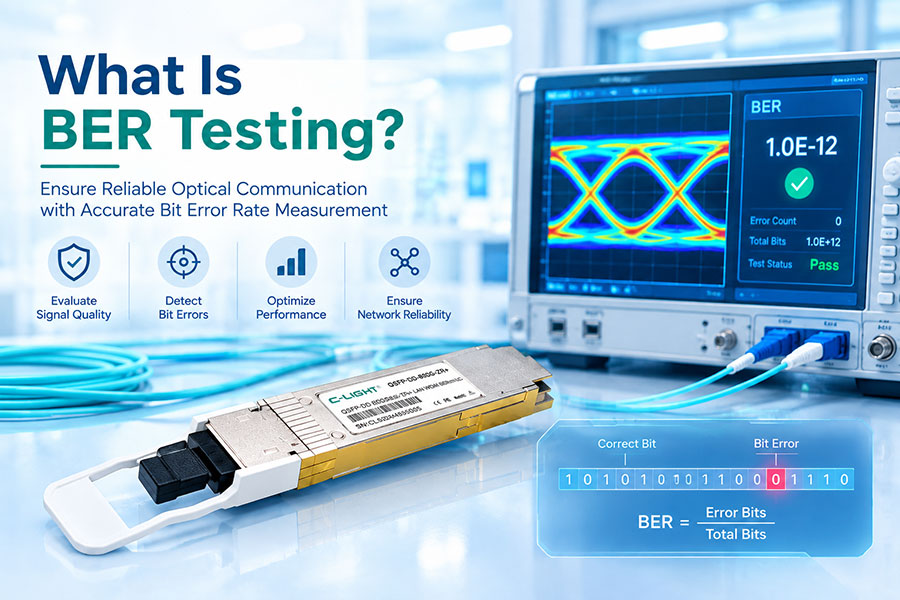
| BER | Ratio of incorrectly received bits to total received bits | Optical power, noise, dispersion, and electrical signal quality. |
| FEC corrected errors | Errors corrected by the receiver's FEC engine | Signal margin, physical channel quality, and error trends. |
| FEC uncorrectable errors | Errors that could not be corrected by FEC | Severe signal impairment, lane problems, or configuration mismatch. |
| CRC or frame errors | Corrupted frames detected at applicable protocol layers | Physical-layer integrity, link quality, and endpoint counters. |
| Lane-specific errors | Errors concentrated on one or more lanes | Individual lane power, electrical channels, and fiber mapping. |
| Link transition logs | History of link up/down events | Intermittent cabling, thermal changes, configuration changes, or module faults. |
Counter names and meanings vary across platforms. BER, FEC statistics, and CRC counters measure different aspects of link performance and should not be treated as interchangeable. Where possible, correlate them with module diagnostics and traffic behavior.
8. Check Temperature, Voltage, and Electrical Signal Integrity
High temperature, abnormal supply voltage, and electrical channel impairments can reduce transceiver operating margin. These problems may be more noticeable on high-speed links with multiple lanes and demanding signal-integrity requirements.
Review the module's temperature, supply voltage, laser bias current, and optical power readings against its specifications. Check airflow, heatsink conditions, port density, and the thermal environment around the module.
If optical power and fiber routing appear normal but errors persist, investigate the host electrical interface. Potential issues include excessive channel loss, reflections, crosstalk, inadequate equalization, or clock and data recovery instability.
For 400G, 800G, and 1.6T systems, compare per-lane diagnostics when available. If the fault follows a module during a controlled swap, the module may be implicated. If the fault remains with the same port or lane, investigate the host, electrical channel, and associated configuration.
9. Use a Controlled Troubleshooting Sequence
Follow a consistent sequence to minimize unnecessary replacements and isolate the failing component.
Record the baseline: Capture link status, alarms, interface counters, module information, and current configuration.
Check both endpoints: Verify module recognition, port settings, speed, FEC, and link-partner compatibility.
Compare optical diagnostics: Record TX and RX power at both ends and check lane-level values where available.
Inspect the optical path: Check connectors, patch cords, polarity, fiber type, and passive components.
Review error trends: Monitor BER, corrected and uncorrectable FEC errors, CRC counters, and link transitions over a defined interval.
Substitute one component at a time: Test a known-good patch cord or compatible transceiver, following the equipment vendor's procedures.
Test another port if appropriate: Determine whether the fault follows the transceiver or remains with the host port.
Validate the correction: Repeat the measurements under comparable conditions and confirm that the link remains stable.
10. When to Use Specialized Test Equipment
Host diagnostics are usually the first step, but external test equipment can provide more definitive measurements when the fault cannot be isolated through software alone.
| Tool | Primary Purpose | Typical Use |
|---|---|---|
| Optical power meter | Measures optical power independently | Verifying TX output or RX power when module readings are questionable. |
| OTDR | Locates fiber events and estimates loss along the fiber | Investigating suspected fiber breaks, bends, or high-loss connections. |
| Fiber inspection tool | Examines connector end-face condition | Identifying contamination or physical damage. |
| Bit Error Rate Tester (BERT) | Measures bit errors under a defined test setup | Validating link performance and isolating physical-layer issues. |
| High-speed electrical test equipment | Evaluates electrical signal integrity | Investigating host channel or transceiver electrical interface problems. |
Choose the test method according to the interface and suspected fault. An OTDR is useful for locating fiber events but does not replace end-to-end BER testing. Similarly, a power meter measures optical power rather than the complete digital signal quality.
Frequently Asked Questions
Module detection confirms that the host can identify the transceiver, but it does not confirm that the optical path is working. Check RX power, fiber polarity, link-partner status, speed configuration, FEC settings, and module compatibility.
Low RX power may result from fiber attenuation, dirty connectors, damaged cabling, passive component loss, or weak transmitter output. Compare the reading with the receiver's specified range and measure the optical path when necessary.
Yes. A link can remain operational while experiencing high BER, FEC corrections, CRC errors, or lane-specific impairments. Review error counter trends and signal diagnostics rather than relying only on the link-up status.
Not necessarily. Check the fiber path, optical power, configuration, and error counters first. Substituting a known-good compatible transceiver is useful when performed as a controlled test, especially if the problem cannot otherwise be isolated.
Higher data rates impose tighter signal-integrity requirements. Excessive electrical channel loss, inadequate equalization, optical signal distortion, lane mapping errors, or incompatible FEC settings may prevent the link from operating reliably at the target rate.
Record the host device model, port number, transceiver part number, link speed, fiber type and length, TX/RX power, alarms, error counters, FEC statistics, and relevant logs. Include the exact failure symptoms and any recent configuration or cabling changes.
Conclusion
Optical transceiver link troubleshooting is most effective when interface status, optical power, fiber condition, compatibility, and error statistics are evaluated together. A link-down condition, intermittent disconnection, and high-error link may require different diagnostic paths, even when they involve the same type of transceiver.
Start with platform diagnostics and TX/RX power readings, then verify cabling, polarity, speed, FEC, and host compatibility. If the issue persists, use controlled component substitution and appropriate optical or electrical test equipment to identify the source and verify the correction.
Need help with optical transceiver selection or compatibility?
Share your interface type, host device model, link distance, and diagnostic results for a more targeted technical assessment.
Contact C-LIGHT >
>

 >
>
 >
>
 >
>
 >
>
 >
>
 >
>
 >
>