TEL:+86 132 6656 7067




Fiber optic transmission distance depends on the optical transceiver's power budget, fiber attenuation, connector and splice losses, operating wavelength, and the receiver's performance requirements. A link may support a long distance on paper but fail in practice if the installed fiber path introduces excessive loss or the optical interface does not meet the required specifications.
For a preliminary distance estimate, engineers can calculate the available optical power budget and divide the remaining loss allowance by the fiber attenuation per kilometer. The result must then be checked against the transceiver's specified reach, receiver overload limit, dispersion constraints, and applicable link standards.
1. The Basic Formula for Fiber Optic Transmission Distance
The maximum distance can be estimated from the optical power budget after accounting for passive component losses and the engineering margin.
Transmitter power should use the minimum specified launch power, while receiver sensitivity should use the applicable specified threshold for the target data rate and performance condition. Both values must come from the relevant transceiver specifications.
2. Calculate the Optical Power Budget
The optical power budget is the difference between the minimum transmitter output power and the receiver sensitivity. It represents the total optical loss the link can tolerate under the specified operating conditions.
| Parameter | Example Value | Meaning |
|---|---|---|
| Minimum Tx power | -3 dBm | Lowest specified optical output power from the transmitter |
| Receiver sensitivity | -18 dBm | Minimum received optical power required to meet the specified performance |
| Available power budget | 15 dB | -3 − (-18) = 15 dB |
These values are illustrative, not specifications for a particular optical transceiver. Actual values vary by module type, wavelength, data rate, and transmission standard.
3. Determine Fiber Attenuation
Fiber attenuation describes the optical power lost as light travels through the fiber. It is usually expressed in dB/km and varies with fiber type, wavelength, and cable condition.
| Fiber Type | Common Operating Wavelengths | Typical Attenuation Reference | Common Applications |
|---|---|---|---|
| Single-mode fiber (OS2) | 1310 nm | Approximately 0.35 dB/km or lower, depending on the fiber specification | Campus, metro, telecom, and data center links |
| Single-mode fiber (OS2) | 1550 nm | Approximately 0.25 dB/km or lower, depending on the fiber specification | Long-distance links and wavelength-division multiplexing |
| Multimode fiber (OM3/OM4) | 850 nm | Often around 3 dB/km or lower, subject to the fiber grade | Short-reach data center and enterprise connections |
These are general planning references rather than universal acceptance limits. Use the installed cable's datasheet, specified wavelength, and applicable cabling standard for an actual link calculation. For multimode fiber, modal bandwidth and transceiver launch conditions can limit reach even when the optical power budget appears sufficient.
4. Include Connector, Splice, and Other Losses
Fiber attenuation is only one part of the total link loss. Every mated connector pair, splice, and additional passive component consumes part of the available optical power budget.
| Loss Source | Illustrative Planning Value | What to Check |
|---|---|---|
| Connector pair | 0.2–0.5 dB per mated pair | Connector cleanliness, mating quality, and measured insertion loss |
| Fusion splice | 0.05–0.1 dB per splice | Splice quality and actual measured loss |
| Passive components | Component-specific | Splitter, patch panel, filter, WDM device, or other insertion loss |
| Engineering margin | Often 2–3 dB for preliminary planning | Maintenance, aging, repairs, uncertainty, and future changes |
The values above are illustrative only. Actual losses depend on component specifications, installation quality, and network design. For PON links, optical splitters can contribute substantial insertion loss and must be included in the total budget.
5. Fiber Optic Transmission Distance Calculation Example
Consider a hypothetical single-mode link with a 15 dB available optical power budget. Assume the fiber attenuation is 0.25 dB/km, the path contains connector and splice losses totaling 1.8 dB, and the design reserves a 2 dB engineering margin.
| Calculation Item | Value |
|---|---|
| Available optical power budget | 15 dB |
| Connector and splice losses | 1.8 dB |
| Engineering margin | 2 dB |
| Remaining fiber loss allowance | 15 − 1.8 − 2 = 11.2 dB |
| Fiber attenuation | 0.25 dB/km |
| Estimated loss-limited distance | 11.2 ÷ 0.25 = 44.8 km |
The estimated loss-limited distance is 44.8 km under these assumptions. It does not mean that any transceiver with a 15 dB budget can reliably transmit over 44.8 km. The module's rated reach, dispersion tolerance, receiver characteristics, and network requirements may impose a shorter limit.
6. Other Factors That Limit Transmission Distance
Transceiver Rated Reach
Optical modules are designed for specific reach classes, such as short-reach, intermediate-reach, and extended-reach applications. A sufficient power budget alone cannot make a short-reach module suitable for a long-distance link.
Chromatic Dispersion and Signal Quality
At higher data rates and longer distances, chromatic dispersion, transmitter characteristics, receiver design, and modulation format can limit performance. Coherent optics, PAM4, NRZ, and other transmission schemes have different reach and signal-processing requirements.
Receiver Overload
The received optical power must remain within the receiver's specified operating range. On short links or links with high launch power, excessive received power can cause errors even when attenuation is low. An appropriate optical attenuator may be needed when permitted by the equipment specifications.
Fiber Type and Connector Interface
Single-mode and multimode fiber are not interchangeable simply because their connectors fit. Confirm the fiber type, wavelength, connector polish, polarity, and transceiver interface. Using the wrong fiber or polarity can prevent a link from operating correctly.
FEC, BER, and Protocol Compatibility
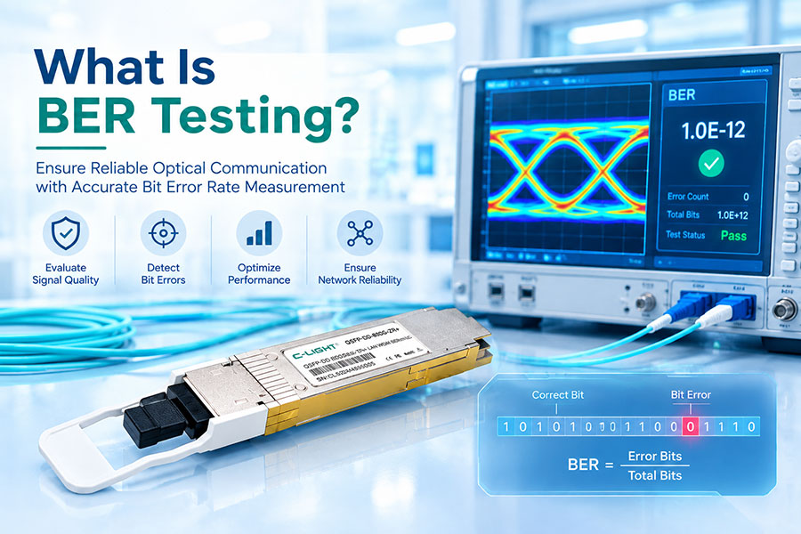
Forward error correction (FEC) requirements and bit error rate (BER) targets depend on the transmission standard and equipment configuration. Verify that both endpoints support compatible optical interfaces and FEC settings. Do not assume that sufficient optical power guarantees acceptable error performance.
7. Typical Fiber Reach by Optical Transceiver Type
The following table provides representative reach classes. Exact supported distances depend on the specific transceiver standard, module specification, fiber type, and link design.
| Transceiver Example | Fiber Type | Representative Reach | Typical Use |
|---|---|---|---|
| 10GBASE-SR SFP+ | Multimode | Up to 300 m on OM3 or 400 m on OM4 under applicable specifications | Server and switch connections |
| 10GBASE-LR SFP+ | Single-mode | Up to 10 km | Campus and enterprise links |
| 100GBASE-SR4 QSFP28 | Multimode | Typically up to 70 m on OM3 or 100 m on OM4 | Short-reach data center links |
| 100GBASE-LR4 QSFP28 | Single-mode | Up to 10 km | Data center interconnects and enterprise backbone links |
| 100GBASE-ER4 QSFP28 | Single-mode | Up to 40 km under applicable specifications | Longer-reach campus and metro links |
These examples refer to common Ethernet optical interface classes. Vendor-specific modules and other protocols may have different specifications. Always confirm the exact standard and product datasheet before deployment.
8. How to Verify the Calculated Distance in the Field
Confirm the optical interface: Check data rate, wavelength, fiber type, connector type, and the transceiver's rated reach.
Collect the optical specifications: Record minimum transmitter power, receiver sensitivity, and receiver overload limits.
Estimate the path loss: Calculate fiber attenuation and add connector, splice, and passive component losses.
Reserve an engineering margin: Allow for installation uncertainty, maintenance, and future changes.
Measure the installed link: Use an optical loss test set or suitable power meter and light source. Use an OTDR when appropriate to locate events and characterize the fiber path.
Check live performance: Review received optical power, alarms, BER, FEC counters, and interface error statistics after the link is activated.
9. Frequently Asked Questions
10.Conclusion
Fiber optic transmission distance can be estimated by combining the optical power budget, fiber attenuation, passive component losses, and engineering margin. However, a reliable link design must also account for transceiver reach specifications, receiver operating limits, dispersion, fiber type, and protocol requirements.
For dependable deployment, calculate the expected loss first, select a compatible optical transceiver, and validate the completed fiber path through optical measurements and live interface diagnostics.
Looking for optical transceivers for your network?
Review optical connectivity solutions for data centers, enterprise networks, and telecom applications.
Contact C-LIGHT >
>

 >
>
 >
>
 >
>
 >
>
 >
>
 >
>
 >
>