TEL:+86 132 6656 7067




AI cluster networking connects large numbers of GPUs, servers, switches, and storage systems with high-speed, low-latency links. As AI workloads scale, optical transceivers and interconnect technologies such as DAC, AOC, AEC, 400G, 800G, and 1.6T optics are becoming critical components of the network fabric.
1. What Is AI Cluster Networking?
AI cluster networking is the high-speed communication infrastructure that connects GPUs, accelerator servers, network switches, storage, and other computing resources within an AI data center.
Unlike conventional enterprise networks, AI clusters can generate large volumes of synchronized traffic between computing nodes. Training workloads frequently exchange gradients, parameters, activations, and datasets across many GPUs at the same time.
The network therefore needs sufficient bandwidth, low latency, predictable performance, high port density, and efficient traffic management.
2. Why Optical Interconnects Matter for AI Clusters
As GPU performance increases, the network connecting those GPUs must also scale. Electrical connections are highly effective over very short distances, but signal loss and power requirements become increasingly challenging as data rates and reach increase.
Optical interconnects use fiber to transport high-speed signals with low attenuation and strong immunity to electromagnetic interference. This makes optical technology particularly useful for switch-to-switch, rack-to-rack, and longer-reach connections within large AI clusters.
High bandwidth
Low latency
Longer transmission reach
High port density
Low electromagnetic interference
Scalable data-center connectivity
Lower cable weight and density
3. AI Cluster Network Architecture
Modern AI clusters commonly use hierarchical or multi-stage network architectures. A typical design includes GPU servers connected to leaf or Top-of-Rack (ToR) switches, which then connect to spine switches.
Larger clusters can use multiple stages of Clos or folded-Clos networking to provide scalable connectivity between large numbers of compute nodes.
| Network Layer | Primary Role | Typical Connectivity |
|---|---|---|
| GPU / Server | Compute and accelerator connectivity | NIC / accelerator interface |
| Leaf / ToR | Connects local servers | DAC, AOC, AEC, optical transceivers |
| Spine | High-capacity aggregation | 400G, 800G and higher-speed optics |
| DCI | Connects distributed facilities | Coherent optics and optical transport |
4. Scale-Up, Scale-Out and Scale-Across
4.1 Scale-Up Networking
Scale-up connects processors or accelerators within a tightly integrated computing system. The distances are generally short, making electrical connections, DACs, and other short-reach technologies important.
4.2 Scale-Out Networking
Scale-out connects large numbers of GPU servers through switches. This is a major application for 400G, 800G, and future 1.6T optical interconnects.
4.3 Scale-Across Networking
Scale-across connects AI resources across data centers or geographically distributed facilities. Longer-reach single-mode optical systems and coherent pluggables become increasingly important as transmission distance increases.
5. 400G Optical Transceivers for AI Networks
400G optical transceivers are widely used in high-speed data-center networks and remain an important building block for AI infrastructure.
Depending on reach and fiber type, common 400G solutions include SR4, DR4, FR4, LR4, and other optical architectures.
| Type | Fiber | Typical Application |
|---|---|---|
| 400G SR | Multimode Fiber | Short-reach AI cluster links |
| 400G DR | Single-mode Fiber | Data-center fabric connections |
| 400G FR | Single-mode Fiber | Longer data-center links |
| 400G LR | Single-mode Fiber | Extended-reach network connections |
6. 800G Optical Transceivers for AI Clusters
800G has become a key bandwidth generation for large AI and hyperscale data-center networks. It allows network operators to increase bandwidth per port while maintaining high switch port density.
800G architectures commonly use multiple 100G-class lanes. Depending on the design, solutions can include SR8, DR8, 2xFR4, and other optical configurations.
800G SR8: Short-reach multimode connectivity.
800G DR8: Single-mode connectivity for data-center fabrics.
800G 2xFR4: Parallel single-mode optical architecture for longer reach.
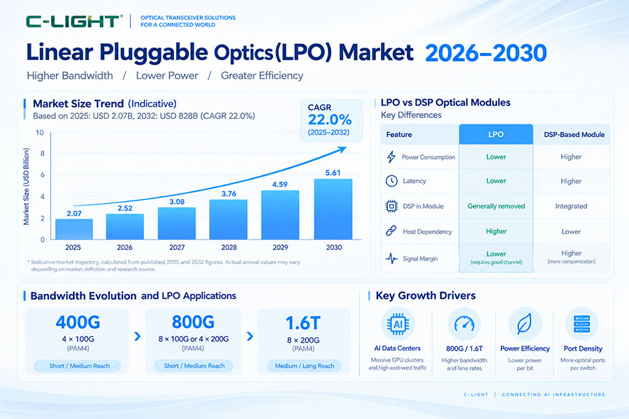
800G LPO: Linear pluggable architecture focused on reducing module power and latency.
7. 1.6T Optical Interconnects
1.6T is the next major bandwidth step for AI cluster networking. Many emerging implementations use eight 200G-class lanes, although the exact architecture depends on the host ASIC, SerDes, optical engine, and module design.
The transition from 800G to 1.6T creates new requirements for:
Higher electrical bandwidth
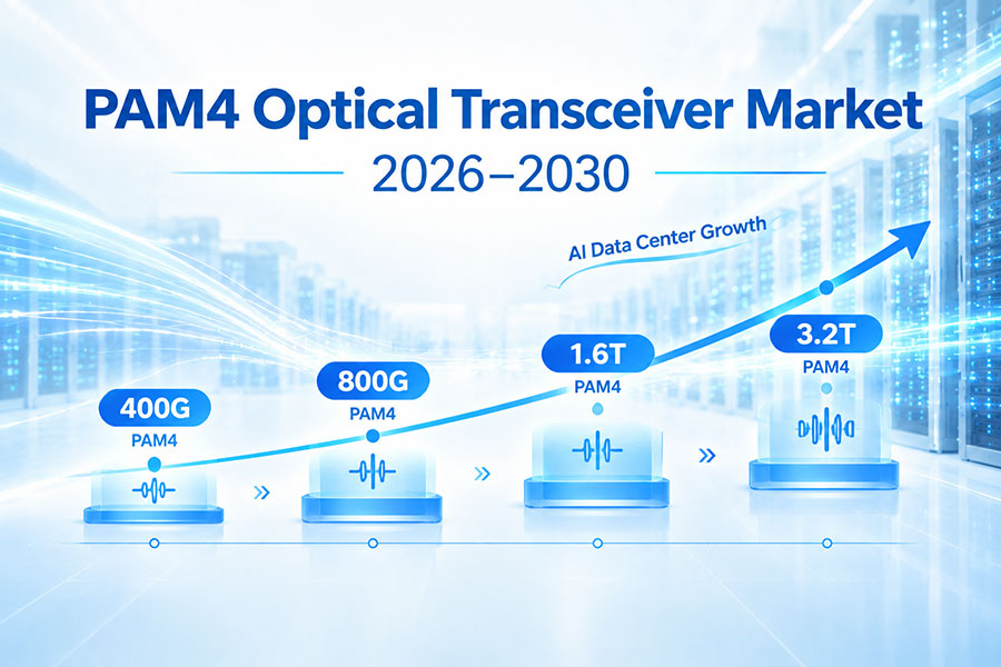
Advanced PAM4 signaling
Improved optical component performance
Higher-density packaging
Thermal management
Lower power per bit
Improved signal integrity
8. PAM4 Signaling in AI Optical Networks
PAM4 is widely used in modern high-speed optical interconnects. It uses four signal levels to encode two bits per symbol, allowing higher data rates without simply doubling the signaling frequency.
However, PAM4 has a smaller vertical eye opening than NRZ and is therefore more sensitive to noise, distortion, insertion loss, crosstalk, and other channel impairments.
For AI cluster networks, maintaining sufficient signal quality requires coordinated design across the host SerDes, PCB, connectors, optical module, fiber, and receiver.
9. DAC, AOC and AEC for AI Cluster Connectivity
Not every AI cluster connection requires an optical transceiver. DAC, AOC, and AEC technologies can provide efficient short-reach connectivity depending on distance, power budget, cost, and system architecture.
| Technology | Main Characteristic | Typical AI Application |
|---|---|---|
| DAC | Passive copper connection | Very short switch-to-switch links |
| AEC | Active electrical cable | Extended short-reach connections |
| AOC | Optical cable with integrated modules | Rack and cluster interconnects |
| Optical Transceiver | Modular optical interface | Switch, rack and fabric connectivity |
The appropriate technology depends on actual link distance and system requirements rather than data rate alone.
10. Optical Transceiver Form Factors
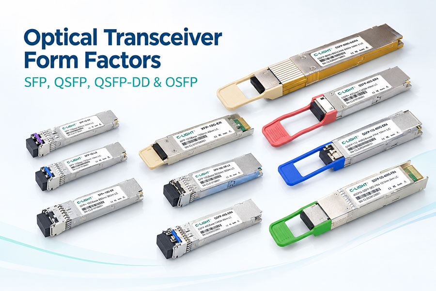
AI cluster networks use several optical transceiver form factors. Lower-speed networks commonly use SFP-family modules, while higher-speed AI fabrics increasingly use QSFP-DD, QSFP112, and OSFP platforms.
| Form Factor | Common Applications |
|---|---|
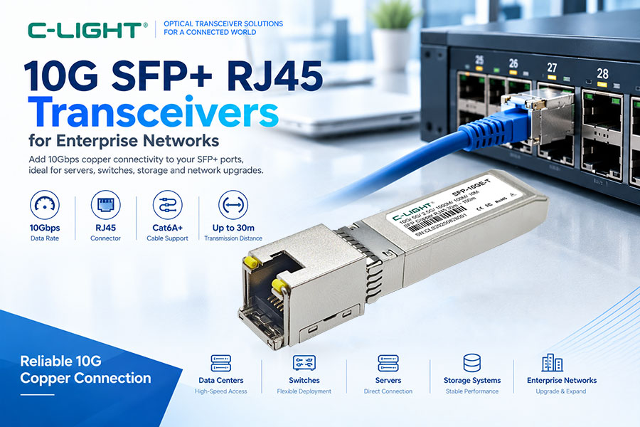
| SFP / SFP+ | Enterprise and lower-speed network connections |
| SFP28 | 25G server and network connectivity |
| QSFP28 | 100G data-center networking |
| QSFP56 | 200G networking |
| QSFP-DD | 400G and higher-density optical networking |
| QSFP112 | 400G and emerging high-speed applications |
| OSFP | 800G and next-generation high-density networks |
11. Optical Reach and Fiber Selection
AI cluster optical connectivity can use multimode or single-mode fiber depending on transmission distance and optical architecture.
MMF: Common for short-reach SR applications.
SMF: Used for DR, FR, LR and longer optical connections.
OM3 / OM4: Common multimode fiber types in data centers.
OM5: Supports specific multimode wavelength-division applications.
OS2: Widely used for single-mode data-center and telecom connectivity.
Fiber selection should be evaluated together with module reach, wavelength, connector type, insertion loss, and the complete link budget.
12. Optical Link Budget for AI Networks
A reliable optical link requires sufficient margin between transmitter output power and receiver sensitivity after accounting for fiber, connectors, splices, and passive components.
The basic link-budget relationship can be expressed as:
Received Optical Power = Transmitter Output Power − Total Link Loss
The resulting received power must remain above the receiver sensitivity with an appropriate engineering margin.
At 800G and 1.6T, optical power and BER margins become increasingly important because higher-speed PAM4 links have tighter performance requirements.
13. LPO Optical Transceivers in AI Networks
Linear Pluggable Optics (LPO) are designed to reduce signal-processing functions inside the optical module. Compared with conventional retimed optical modules, LPO architectures can move more of the signal-conditioning responsibility toward the host switch ASIC or SerDes.
Potential advantages include:
Lower optical module power
Reduced module thermal load
Potentially lower latency
Simplified module signal architecture
The tradeoff is greater dependence on the electrical channel and host SerDes. PCB loss, connector quality, package characteristics, optical components, and signal integrity must be carefully controlled.
14. LPO vs Conventional Retimed Optics
| Feature | LPO | Retimed Optics |
|---|---|---|
| Module DSP | Reduced or removed | Typically included |
| Module Power | Potentially lower | Generally higher |
| Latency | Potentially lower | Higher due to additional processing |
| Host SerDes Dependence | Higher | Lower |
| Signal Integrity Requirement | More demanding | More processing margin |
| Interoperability | Requires careful validation | More established |
15. Optical Transceiver Power and Thermal Management
Power efficiency is a critical consideration in AI clusters because a large network may contain thousands of high-speed optical ports.
Optical module power contributes directly to switch thermal load. Higher-power modules can increase the cooling requirements of densely populated switches.
Important power-consuming components can include:
DSP
Laser or VCSEL
EML
Driver
TIA
FEC and related processing
Module management electronics
For this reason, power per bit is often more useful than module power alone when comparing different generations of optical interconnects.
16. Silicon Photonics for AI Optical Interconnects
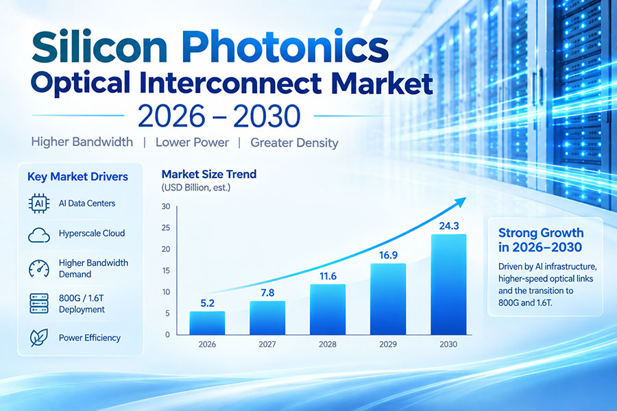
Silicon photonics integrates multiple optical functions into a photonic integrated circuit. Depending on the architecture, it can integrate waveguides, modulators, multiplexers, splitters, and photodetectors.
Silicon photonics is particularly relevant to high-density optical systems because integration can reduce the number of discrete optical components and support multi-channel architectures.
It can be used with different laser and packaging approaches and should not be treated as synonymous with LPO. Silicon photonics describes an optical integration technology, while LPO describes a signal-processing and module architecture.
17. Co-Packaged Optics and Optical Engines
As switch ASIC bandwidth increases, the electrical distance between the ASIC and front-panel optical modules becomes more challenging.
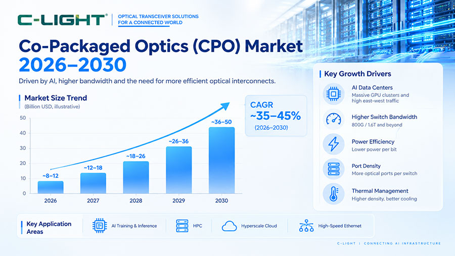
Optical engines and co-packaged optics can move optical functionality closer to the switching silicon, potentially reducing electrical channel loss and improving bandwidth density.
These technologies are particularly relevant to future high-radix AI switches, although pluggable optics remain important because they provide modularity, field replacement, and flexible deployment.
18. Ethernet and InfiniBand AI Networks
Ethernet and InfiniBand are both important networking technologies for AI clusters. Their implementation depends on the system architecture, switching design, software ecosystem, congestion-management requirements, and application workload.
Optical transceivers can be used in both networking environments when the physical-layer specifications and module interoperability requirements are satisfied.
19. Congestion and Network Performance
AI training can generate synchronized traffic patterns such as all-reduce and all-to-all communication. Large numbers of GPUs may transmit data simultaneously, creating temporary traffic bursts and congestion.
Network performance is influenced by:
Bandwidth
Latency
Jitter
Packet loss
Congestion
Topology
Oversubscription
Flow-control mechanisms
Optical bandwidth alone cannot guarantee application performance. The complete network architecture must be designed to handle the traffic patterns generated by distributed AI workloads.
20. Testing AI Optical Interconnects
High-speed optical modules should be validated under realistic host and environmental conditions before large-scale deployment.
Important testing parameters include:
Optical output power
Receiver sensitivity
Transmitter and receiver eye quality
Bit error rate
Pre-FEC and post-FEC performance
Temperature performance
Module power consumption
Host electrical channel performance
Interoperability
For PAM4 systems, testing should also consider equalization, channel loss, crosstalk, and other high-speed electrical impairments.
21. How to Select Optical Transceivers for AI Clusters
Optical module selection should start with the network architecture rather than the transceiver data rate alone.
Determine port speed: Identify whether the network requires 400G, 800G, 1.6T, or another rate.
Define transmission distance: Select SR, DR, FR, LR, or another architecture according to the actual link.
Select fiber: Determine whether MMF or SMF is required.
Choose the form factor: Check OSFP, QSFP-DD, QSFP112, or other host-port requirements.
Check power limits: Confirm that module power fits the switch thermal envelope.
Validate interoperability: Test the module with the target switch ASIC, NIC, and host platform.
Check management: Verify CMIS or other required management interfaces.
Evaluate BER and FEC: Confirm sufficient link margin under actual operating conditions.
22. AI Cluster Cabling Considerations
High-density AI clusters require careful physical-layer planning. Increasing port counts can quickly create complex fiber and cable-management requirements.
MPO/MTP connectors are commonly used for parallel optical connections, while LC duplex connections remain important for many single-mode and duplex optical architectures.
Cabling design should account for polarity, bend radius, insertion loss, cable routing, patch-panel density, airflow, and serviceability.
23. Optical Interconnects from Rack to Data Center
AI clusters typically require multiple types of physical connectivity. Very short connections may use DAC, while AEC and AOC can address other short-reach requirements. Optical transceivers provide modular connectivity across rack and fabric layers, while coherent optical systems can connect geographically separated data centers.
This creates a layered interconnect ecosystem rather than a single technology serving every link.
24. AI Cluster Networking Roadmap
| Generation | Networking Focus | Optical Technology |
|---|---|---|
| 400G | Large-scale data-center deployment | SR, DR, FR, LR and related optics |
| 800G | AI and high-density switching | SR8, DR8, 2xFR4, LPO and related solutions |
| 1.6T | Next-generation AI fabrics | 200G-class lane architectures and advanced optical engines |
| Beyond 1.6T | Higher bandwidth and density | Advanced photonics, co-packaged and near-packaged optics |
25. Future Trends in AI Optical Interconnects
The evolution of AI networking is likely to continue toward higher bandwidth, greater optical integration, lower power consumption, and tighter integration between switching silicon and photonics.
800G deployment expansion
1.6T optical interconnect adoption
Higher-speed SerDes
LPO and other linear architectures
Silicon photonics
Optical engines
CPO and NPO
Higher-density fiber connectivity
Improved power efficiency
Advanced optical testing
26. Conclusion
AI cluster networking depends on a combination of high-performance switches, GPUs, NICs, fiber infrastructure, and high-speed optical interconnects. Optical transceivers provide the scalable connectivity required between servers, switches, racks, and data-center fabrics.
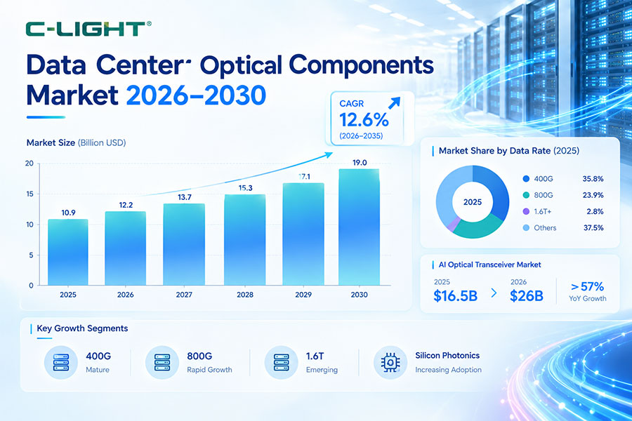
400G remains an important deployment generation, while 800G is becoming increasingly important for AI clusters and 1.6T is emerging as the next step in network bandwidth. At the same time, LPO, silicon photonics, optical engines, CPO, and NPO are creating new approaches to improve power efficiency, bandwidth density, and signal integrity.
The most effective AI network design therefore considers bandwidth, reach, latency, power, thermal performance, cabling, interoperability, and total system architecture together.
 >
>

 >
>
 >
>
 >
>
 >
>
 >
>
 >
>
 >
>