TEL:+86 132 6656 7067





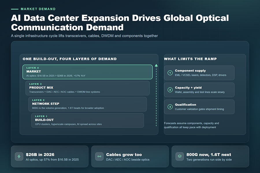
Artificial intelligence is changing the bandwidth requirements of modern data centers. Large GPU clusters, distributed AI training systems, high-performance computing platforms, and hyperscale cloud infrastructure generate increasingly demanding traffic between processors, memory systems, storage networks, and switching equipment. As these environments scale, 400G connectivity is giving way to broader 800G deployment, while 1.6T interfaces are emerging as the next step in high-density network design.
The transition from 800G to 1.6T represents more than a doubling of nominal link bandwidth. It affects the electrical interfaces inside switches, optical module architecture, signal integrity, thermal management, fiber connectivity, and the way network capacity is distributed across racks and data center facilities.
Optical transceivers remain essential for connections that require high bandwidth over distances beyond the practical reach of passive copper. At shorter distances, DAC and active electrical cable technologies continue to provide alternatives. Meanwhile, onboard optics and co-packaged optics are attracting attention as network designers seek to reduce electrical channel losses and improve power efficiency.
1. Why 800G and 1.6T Connectivity Are Becoming Important
AI computing systems place unusually high demands on network infrastructure. During distributed training, large volumes of data move between GPUs and other accelerator resources. The network must support high aggregate bandwidth, predictable latency, and efficient communication across large numbers of endpoints.
Traditional data center architectures were designed around a mixture of server access, storage traffic, and general-purpose cloud workloads. AI clusters introduce different traffic patterns, including intensive east-west communication between accelerators and high-bandwidth links between leaf, spine, and core switching layers.
As GPU counts and switch capacities increase, network operators need more bandwidth per port and more aggregate capacity within each rack or fabric. Moving from 400G to 800G and then toward 1.6T can increase the capacity of individual connections and help reduce the number of physical interfaces required for a given bandwidth target.
| Connectivity Generation | Aggregate Link Rate | Network Development Focus |
|---|---|---|
| 400G | 400 Gb/s | Established high-speed data center and AI network connectivity |
| 800G | 800 Gb/s | Higher switch-port bandwidth and larger AI cluster fabrics |
| 1.6T | 1.6 Tb/s | Next-generation high-density switching and accelerator connectivity |
| 3.2T and beyond | Future aggregate interface generations | Continued development of electrical and optical integration |
Industry research published by Goldman Sachs in April 2026 identified the migration from 800G toward 1.6T as an important stage in optical networking development, with subsequent transitions toward 3.2T and higher-capacity interfaces. The timing of deployment will vary by cloud provider, switch platform, application, and supply-chain readiness.
2. The Technical Architecture Behind 800G and 1.6T Links
High-speed optical connectivity depends on coordinated operation between the switch ASIC, host electrical interface, optical module, fiber plant, and receiving device. Increasing the optical link rate requires improvements across this complete signal path.
Many 800G and 1.6T architectures use PAM4 signaling. PAM4 represents four signal levels and carries two bits per symbol, allowing more information to be transmitted per symbol than traditional NRZ signaling. This higher information density supports faster interfaces, but it also creates stricter requirements for signal integrity and error management.
Lane count and lane rate are central to the architecture. An 800G interface may use eight lanes operating at approximately 100 Gb/s per lane or four lanes operating at approximately 200 Gb/s per lane, depending on the electrical and optical implementation. A common 1.6T architecture uses eight lanes operating at approximately 200 Gb/s per lane.
| Interface Architecture | Lane Configuration | Approximate Aggregate Rate | Typical Signaling Context |
|---|---|---|---|
| 400G 8-lane | 8 × 50 Gb/s | 400 Gb/s | PAM4 |
| 800G 8-lane | 8 × 100 Gb/s | 800 Gb/s | PAM4 |
| 800G 4-lane | 4 × 200 Gb/s | 800 Gb/s | Higher-speed PAM4 electrical and optical implementations |
| 1.6T 8-lane | 8 × 200 Gb/s | 1.6 Tb/s | Next-generation PAM4 interfaces |
These lane configurations are architectural examples rather than a complete list of standardized implementations. The actual electrical and optical lane mapping depends on the module specification, host interface, modulation implementation, and system design.
3. 800G Optical Connectivity Supports Large-Scale AI Networks
800G optical connectivity is becoming an important building block for high-performance data center networks. It provides twice the aggregate bandwidth of a 400G link and supports higher-capacity connections between switches, racks, and data center network layers.
Different optical configurations address different reach and fiber requirements. Short-reach multimode solutions are used for suitable in-building links, while single-mode options support longer connections and higher-density network designs.
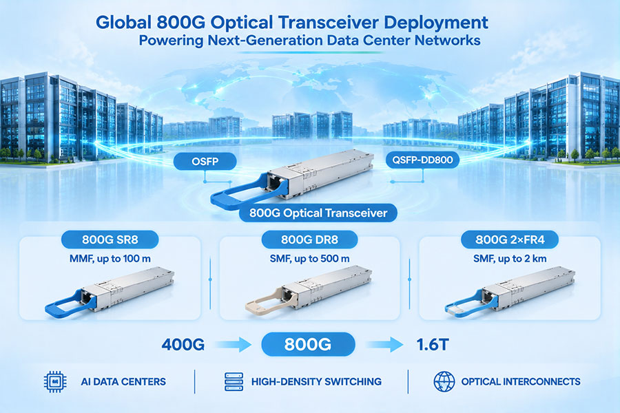
| 800G Optical Configuration | Fiber Type | Representative Reach | Typical Application |
|---|---|---|---|
| 800G SR8 | Multimode fiber | Up to 100 m | Short-reach data center connections |
| 800G DR8 | Single-mode fiber | Up to 500 m | Switch-to-switch and rack-level optical links |
| 800G 2×FR4 | Single-mode fiber | Up to 2 km | Longer data center and campus interconnections |
| 800G VR8 | Multimode fiber | Up to 50 m | Very short-reach high-density connections |
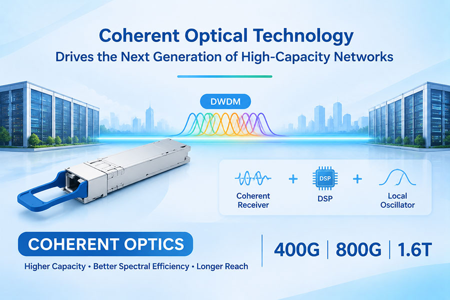
| 800G coherent ZR/ZR+ | Single-mode fiber | Application- and system-dependent | Metro and data center interconnection |
These distances represent common product classes or representative configurations, not guaranteed reach for every implementation. Fiber grade, connector loss, optical budget, FEC, host compatibility, and operating conditions must be verified for each link.
For AI infrastructure, 800G modules are particularly relevant to high-capacity Ethernet and InfiniBand environments. However, Ethernet and InfiniBand are distinct networking technologies. A module's support for one does not automatically establish compatibility with every implementation of the other.
4. 1.6T Connectivity Introduces a New Bandwidth Density Level
As switch ASIC bandwidth increases, 1.6T optical connectivity provides a path to higher port capacity without requiring a proportional increase in the number of physical connections. This is particularly relevant to large AI clusters where switch front-panel space, rack density, cooling capacity, and fiber management are increasingly constrained.
A common 1.6T optical architecture uses eight 200G electrical lanes and an optical engine designed to support the corresponding aggregate data rate. The OSFP1600 form factor is one of the packaging directions associated with this generation.
The OSFP-RHS design is also relevant to high-density equipment layouts. RHS means Reduced Height Sink, referring to a reduced-height heat-sink design intended for specific host-system thermal and mechanical requirements. It should not be assumed that every RHS module is interchangeable with every OSFP or OSFP1600 host cage. Mechanical, thermal, electrical, and management compatibility must be confirmed against the host platform.
Representative 1.6T optical configurations include:
1.6T DR8: A parallel single-mode optical architecture designed for short-reach high-bandwidth connections.
1.6T 2DR4: A two-port 800G-oriented optical arrangement within a 1.6T aggregate module architecture, depending on the product implementation.
1.6T 2FR4: A two-port 800G-oriented architecture using four-wavelength FR4 optical interfaces per port in supported designs.
Exact optical lane mapping, connector configuration, wavelength plan, reach, and host electrical interface must be taken from the individual product specification. Similar product names do not guarantee identical optical architecture.
5. Optical Transceivers, DAC, AEC, AOC, and ACC Serve Different Distances
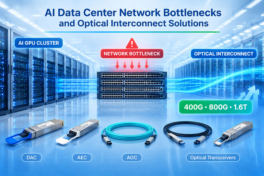
High-speed data center connectivity is not based on optical transceivers alone. Copper and active cable technologies remain important because different network connections have different distance, power, latency, and cost requirements.
The choice between optical modules and high-speed cables should be based on the physical connection, host interface, signal-integrity requirements, and deployment environment.
| Connectivity Type | Transmission Medium | Main Characteristics | Typical Deployment |
|---|---|---|---|
| DAC | Passive copper | No optical conversion; low power and simple construction | Very short connections within racks |
| AEC | Active copper | Uses active signal conditioning or retiming, depending on design | Short-reach high-speed rack and equipment connections |
| AOC | Integrated optical fiber cable | Optical transmission with permanently attached cable assemblies | Short- and medium-distance equipment connections |
| ACC | Active copper | Active signal conditioning without necessarily using the same retiming architecture as AEC | Selected short-reach high-speed links |
| Optical transceiver | Optical fiber with pluggable modules | Separate optical modules and fiber cabling | Rack-to-rack, row-to-row, and longer data center links |
DAC is often suitable when the connection is very short and the host electrical channel can support the required data rate. AEC and ACC introduce active electronics to extend or condition electrical links within their specified operating range. AOC integrates optical conversion into a cable assembly, while pluggable optical transceivers provide more flexibility in fiber selection, reach, and network maintenance.
At 800G and 1.6T, cable selection requires careful attention to connector type, host electrical interface, supported lane rate, cable length, power consumption, and platform compatibility. A cable that supports a particular aggregate rate on one host platform should not automatically be assumed to work on another.
6. PAM4, DSP, and FEC Enable Higher-Speed Optical Links
Moving to 800G and 1.6T increases the demands placed on high-speed electrical and optical signal transmission. PAM4 modulation helps increase data density, while digital signal processing and forward error correction support reliable operation under increasingly challenging signal conditions.
In PAM4 signaling, four amplitude levels represent two bits per symbol. Compared with NRZ, this allows a higher bit rate at a given symbol rate, but the smaller separation between adjacent signal levels makes the system more sensitive to noise, distortion, and other channel impairments.
DSP performs functions such as equalization, signal conditioning, and compensation for transmission impairments. The exact processing architecture varies by module type and application.
FEC adds redundant information that allows the receiver to detect and correct a defined range of transmission errors. At higher data rates, FEC is an important part of maintaining link reliability, but it also has implementation-specific latency and power implications.
| Technology | Primary Function | Importance at 800G and 1.6T |
|---|---|---|
| PAM4 | Encodes two bits per symbol using four signal levels | Increases information density per signaling event |
| DSP | Processes and equalizes high-speed signals | Supports signal integrity at higher lane rates |
| FEC | Detects and corrects transmission errors | Improves error performance within specified operating limits |
| High-speed SerDes | Converts data between parallel and serial electrical interfaces | Enables higher-bandwidth communication between ASICs and modules |
These technologies must operate as part of a coordinated host-to-module channel. A high-performance optical engine cannot compensate for every limitation in a poorly designed electrical path, unsuitable connector, or incompatible host interface.
7. Thermal Management and Power Efficiency Become More Important
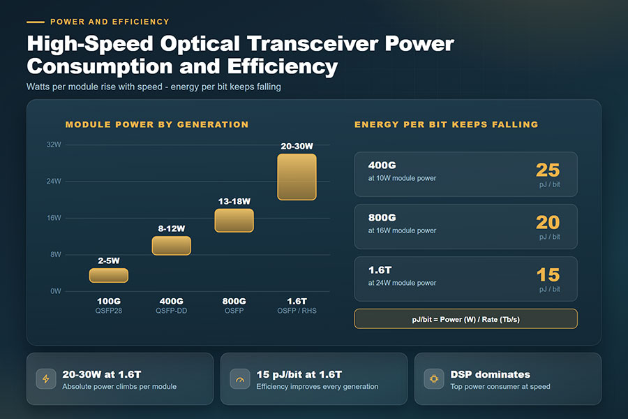
Higher bandwidth density increases the importance of thermal and power management. Optical modules contain laser sources, drivers, photodetectors, DSP components, and power-management circuits. As lane rates and integration levels increase, the thermal design of the module and host system becomes more demanding.
In large AI data centers, hundreds or thousands of high-speed optical connections may operate within a relatively compact space. Even modest differences in module power consumption can affect total rack power, cooling requirements, and operating costs.
Important design considerations include:
Module power consumption: Higher-speed modules can require more electrical power, depending on architecture and implementation.
Heat-sink design: The module must transfer heat effectively to the host cooling environment.
Airflow: Switch airflow direction and system-level cooling design affect module operating temperature.
Thermal interface: Mechanical contact and heat-transfer characteristics influence cooling performance.
Liquid cooling compatibility: Host-level liquid cooling may be used in some platforms, but module compatibility depends on the complete mechanical and thermal design.
Power efficiency: Network operators increasingly evaluate energy consumption per transmitted bit rather than bandwidth alone.
OSFP-RHS packaging is one approach used in specific high-density host environments. Its reduced-height heat-sink design addresses particular mechanical and thermal constraints, but it is not a universal cooling solution. Module selection must follow the host manufacturer's thermal specifications and validated operating conditions.
8. NPO and CPO Are Changing the Future of Optical Integration
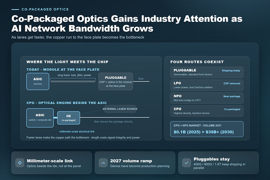
Traditional pluggable optical modules connect to switch ASICs through high-speed electrical traces and host connectors. As electrical lane rates increase, these connections can consume more power and become increasingly difficult to manage because of insertion loss and signal-integrity limitations.
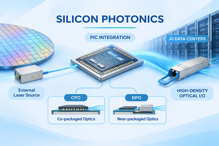
Near-Packaged Optics (NPO) and Co-Packaged Optics (CPO) are being developed to bring optical engines closer to switching or computing silicon. Shortening the electrical path can help reduce signal losses and improve the potential power efficiency of high-bandwidth systems.
| Architecture | Optical Placement | Potential Advantages | Engineering Considerations |
|---|---|---|---|
| Pluggable optics | Removable module at the equipment front panel | Serviceability, flexibility, and established deployment practices | Electrical channel length and module thermal limits |
| NPO | Optical engine positioned near the main ASIC | Shorter electrical paths and potential power improvements | Packaging, serviceability, and system integration |
| CPO | Optical engines integrated closely with the switch or compute package | Potentially lower electrical I/O power and higher bandwidth density | Laser management, optical packaging, repair, and manufacturing complexity |
These architectures are not interchangeable module types. NPO and CPO involve changes to system-level packaging and optical integration, whereas pluggable transceivers remain removable modules connected through standardized host interfaces.
Pluggable optics will continue to serve many data center applications because of their flexibility and established maintenance model. NPO and CPO are additional architectural options for platforms where bandwidth density and electrical I/O power become major constraints.
9. Fiber Connectivity and Cabling Must Scale with Port Bandwidth
Higher-speed optical modules increase the importance of structured fiber infrastructure. A network containing large numbers of 800G and 1.6T ports may require extensive MPO/MTP connectivity, LC patching, trunk cables, fiber distribution panels, and careful cable routing.
The optical connector must match the transceiver interface and the intended fiber architecture. Parallel optical modules often use multi-fiber connectors, while duplex or wavelength-multiplexed interfaces may use LC connectors. The exact connector arrangement depends on the module specification.
High-density fiber management is important for several reasons:
Maintaining correct transmit and receive polarity.
Reducing insertion loss at connectors and mating points.
Preventing excessive bend radius and cable stress.
Supporting easier identification and maintenance.
Providing sufficient space for airflow and equipment access.
Allowing future network expansion without extensive recabling.
Connector cleanliness is particularly important at high optical data rates. Dust and contamination can increase insertion loss or cause unstable link performance. Inspection and cleaning procedures should therefore be included in installation and maintenance processes.
10. 800G and 1.6T Connectivity in AI Network Architectures
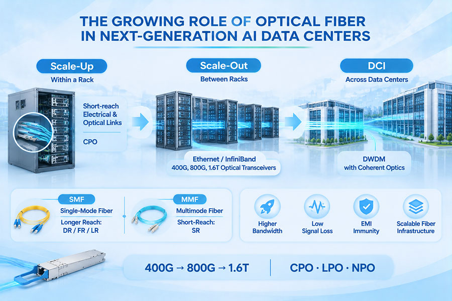
AI data center networks commonly use high-bandwidth switching fabrics to connect large groups of accelerators. The network topology may include connections within a server, between servers in a rack, between racks, and across multiple data center buildings.
Different network layers have different requirements. Short electrical connections may be suitable within a server or rack, while optical links become increasingly important as distances and aggregate bandwidth increase.
| Network Layer | Typical Connectivity Requirement | Potential Technology Options |
|---|---|---|
| GPU-to-GPU within a server | Very high bandwidth and low latency | Platform-specific electrical interconnects and integrated links |
| Server-to-top-of-rack switch | Short-reach high-speed connectivity | DAC, AEC, AOC, and optical transceivers |
| Rack-to-rack | Higher bandwidth across greater physical distances | 800G optical modules, AOC, and structured fiber |
| Leaf-to-spine switching | High aggregate fabric bandwidth | 800G and emerging 1.6T optical interfaces |
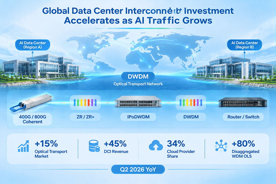
| Data center interconnection | Campus or metro-scale connectivity | Single-mode optics and coherent solutions where appropriate |
Actual network design depends on the selected accelerator platform, switch architecture, topology, and required oversubscription ratio. A 1.6T link is not automatically the best choice for every connection. The right interface should be selected according to the traffic pattern, link distance, port density, and total system cost.
11. Interoperability and Testing Are Essential for High-Speed Deployment
As optical interfaces move toward 800G and 1.6T, interoperability becomes increasingly important. A module must meet the electrical, optical, mechanical, and management requirements of its target host system.
Form-factor compatibility alone is insufficient. Two modules that appear physically similar may differ in electrical lane mapping, modulation, firmware, power class, thermal behavior, or management implementation.
Before deployment, network operators and equipment suppliers should verify the following areas:
Host interface: Confirm electrical lane count, lane rate, and supported signaling.
Optical interface: Check wavelength, fiber type, connector, optical power, and reach.
Protocol support: Verify Ethernet or InfiniBand compatibility for the intended application.
Management interface: Confirm CMIS or other required management specifications and diagnostic functions.
Thermal operation: Validate module temperature under the host platform's airflow and cooling conditions.
Interoperability: Test the module with the actual switch, NIC, or accelerator platform.
Link performance: Evaluate BER, FEC behavior, optical power, and link stability.
Production testing should also cover optical transmitter and receiver performance, electrical characteristics, power consumption, temperature behavior, and digital diagnostic monitoring. For high-density AI infrastructure, testing under realistic host conditions is especially important because a module's standalone performance does not always represent its behavior in the final system.
12. C-LIGHT 800G and 1.6T Optical Connectivity Portfolio
As data center operators upgrade from 400G to 800G and prepare for 1.6T infrastructure, optical transceivers and high-speed cables must support different connection distances and host architectures.
C-LIGHT provides high-speed optical connectivity products for data centers, AI clusters, cloud networks, and high-performance computing environments.
C-LIGHT 800G OSFP Optical Transceiver – Supports multiple configurations, including VR8 up to 50 m, SR8 up to 100 m, DR8 up to 500 m, and 2×FR4 up to 2 km. The product portfolio also includes selected 800ZR and 800ZR+ coherent configurations.
C-LIGHT 1.6T OSFP-RHS Optical Transceiver – Uses an 8×200G PAM4 architecture with integrated DSP and FEC. The product family includes 2DR4 and 2FR4 configurations for next-generation high-density data center connectivity.
C-LIGHT 800G AEC Cable – An active electrical connectivity option for compatible short-distance high-speed connections in AI and data center environments.
C-LIGHT 800G AOC Cable – Provides integrated optical cable connectivity for high-bandwidth links where a fixed optical cable assembly is suitable.
C-LIGHT DAC, AEC, ACC, and AOC Solutions – A broader high-speed cable portfolio supporting different electrical and optical interconnection requirements.
C-LIGHT Optical Transceiver Portfolio – Covers multiple data rates, form factors, and optical transmission applications, including 400G, 800G, 1.6T, and DWDM DCO solutions.
For 1.6T deployment, the selected module must match the host's OSFP1600 electrical and mechanical requirements. For 800G links, the correct optical configuration should be selected according to the required distance, fiber type, connector, and network protocol.
DAC, AEC, ACC, and AOC products address different physical connection requirements. They should be selected based on cable length, host compatibility, signal integrity, power consumption, and installation conditions rather than aggregate data rate alone.
13. The Next Stage of Optical Communication Development
The move toward 800G and 1.6T is part of a broader transformation in optical communication. Increasing AI workloads and cloud infrastructure capacity are driving development across optical components, high-speed electronics, photonic integration, and network architecture.
Several trends are likely to shape future connectivity systems:
Higher electrical lane rates: Continued development of SerDes technology will support higher aggregate bandwidth in future switch and accelerator platforms.
Advanced optical integration: Silicon photonics and other photonic integration approaches may improve optical engine density and manufacturing scalability.
Improved power efficiency: Module, DSP, and system-level improvements will help manage the energy requirements of high-bandwidth networks.
Expanded optical integration: NPO and CPO will continue to develop for systems requiring high bandwidth density and shorter electrical paths.
Higher-density fiber infrastructure: MPO/MTP connectivity, structured cabling, and automated fiber management will become increasingly important.
More flexible network architectures: Ethernet, InfiniBand, and emerging AI networking designs will continue to influence optical interface requirements.
Progress will depend on more than the availability of faster optical modules. Switch ASIC development, electrical channel design, optical component performance, manufacturing capacity, interoperability, and cooling infrastructure must advance together.
14. Conclusion
800G and 1.6T connectivity are shaping the next phase of optical communication development. The growth of AI computing, hyperscale data centers, and high-performance networking is increasing demand for greater bandwidth density, improved signal integrity, and more efficient interconnect architectures.
800G optical transceivers are supporting the expansion of high-capacity data center networks, while 1.6T solutions are moving toward the next generation of switch and accelerator platforms. DAC, AEC, ACC, and AOC technologies continue to serve important roles in short-distance connectivity, while pluggable optical modules provide flexible fiber-based connections across larger network environments.
At the same time, PAM4, DSP, FEC, improved thermal design, silicon photonics, NPO, and CPO are changing how high-speed links are implemented. The successful deployment of these technologies requires coordinated development across electrical interfaces, optical components, fiber infrastructure, and system-level engineering.
As network bandwidth requirements continue to grow, 800G and 1.6T connectivity will remain important technologies for building scalable AI data centers and next-generation optical communication infrastructure.
For 800G and 1.6T optical transceivers, high-speed cables, and customized connectivity requirements, Contact C-LIGHT for product information and technical support.
 >

 >
 >
 >
 >
 >
 >
 >