TEL:+86 132 6656 7067





High-speed optical connectivity depends on two important signal-processing components: the SerDes inside the host ASIC and the Optical DSP commonly found inside a pluggable transceiver. Both work with high-speed electrical data, but they serve different roles in the overall communication system. SerDes establishes the electrical data interface between chips and optical modules, while Optical DSP performs additional signal conditioning and, in some architectures, optical-domain compensation. Their relationship becomes particularly important in 400G, 800G, and 1.6T networks, where lane rates, electrical channel loss, power consumption, and signal integrity increasingly influence system design.
1. What Is SerDes?
SerDes stands for Serializer/Deserializer. It is a high-speed electrical interface circuit that converts parallel data into serial data for transmission and converts received serial data back into parallel data at the other end.
In a network switch, router, NIC, or accelerator, the ASIC processes data internally across parallel digital interfaces. The SerDes converts this data into high-speed serial electrical signals that can travel across PCB traces, connectors, cables, or an optical module's electrical interface.
On the transmit side, the serializer combines parallel data into a serial stream. On the receive side, the deserializer reconstructs parallel data from the incoming serial stream.
Modern SerDes implementations also include substantial analog and digital signal-processing capabilities. Depending on the generation and architecture, these may include transmit pre-emphasis, continuous-time linear equalization (CTLE), feed-forward equalization (FFE), decision-feedback equalization (DFE), clock and data recovery (CDR), and adaptive calibration.
Typical SerDes functions
Serialization: Converts parallel data into high-speed serial electrical signals.
Deserialization: Reconstructs parallel data from received serial signals.
Clock and data recovery: Recovers timing information from incoming serial data.
Equalization: Compensates for electrical channel loss and inter-symbol interference.
Signal conditioning: Adjusts transmit and receive characteristics to maintain signal integrity.
Lane management: Supports the electrical lanes required by the host interface.
SerDes is therefore more than a basic data converter. It is a high-speed electrical transceiver subsystem that directly influences the signal quality and reach of the electrical channel.
2. What Is an Optical DSP?
An Optical DSP is a digital signal processor designed for the signal-processing requirements of an optical communication system. It is commonly integrated into high-speed optical transceivers, particularly DSP-based pluggable modules and coherent optical modules.
On the transmit side, the Optical DSP receives electrical data from the host interface, processes the signal according to the module architecture, and prepares it for conversion into an optical waveform. Depending on the implementation, it may perform digital equalization, pre-compensation, lane processing, modulation-related processing, and other functions.
On the receive side, the optical front end converts incoming light into an electrical signal. The Optical DSP processes the resulting waveform to recover data and compensate for supported signal impairments.
Typical Optical DSP functions
Transmit equalization: Shapes the electrical waveform before optical modulation.
Receive equalization: Compensates for selected distortions in the received electrical signal.
Clock recovery: Supports timing recovery and signal synchronization.
Signal conditioning: Improves waveform quality for the optical transmission system.
Lane processing: Supports lane mapping, alignment, and gearbox functions where implemented.
Optical impairment compensation: In coherent systems, processes effects such as chromatic dispersion, polarization-related impairments, and phase noise.
FEC support: May include forward error correction functions in architectures that integrate FEC into the module DSP.
Not every Optical DSP performs all these functions. A short-reach PAM4 transceiver and a coherent ZR or ZR+ module have different processing requirements. The exact DSP architecture depends on the optical interface, modulation format, reach, and system design.
3. SerDes vs Optical DSP: Main Differences
| Technical Factor | SerDes | Optical DSP |
|---|---|---|
| Full Name | Serializer/Deserializer | Optical Digital Signal Processor |
| Primary Role | Converts parallel and serial electrical data | Processes signals for optical transmission and reception |
| Typical Location | Host ASIC, NIC, switch chip, or other high-speed interface IC | Optical transceiver or optical communication subsystem |
| Signal Domain | Primarily electrical | Digital processing of electrical representations of optical-link data |
| Serialization | Core function | May contain SerDes interfaces, but this is not its defining role |
| Deserialization | Core function | May contain SerDes interfaces, but this is not its defining role |
| Electrical Equalization | Transmit and receive equalization for electrical channels | May perform additional electrical signal equalization inside the module |
| Optical Impairment Compensation | Not its primary responsibility | Can perform advanced optical signal compensation, especially in coherent systems |
| Clock Recovery | Commonly included in the SerDes receiver | May perform additional timing and synchronization functions |
| FEC | Not an inherent SerDes function; may interface with host PCS/FEC blocks | May integrate FEC in supported transceiver architectures |
| Primary Application | High-speed chip-to-chip and host-to-module electrical links | Optical transceiver signal processing and optical communication |
The distinction is functional rather than absolute. A modern Optical DSP can contain internal SerDes interfaces, while a modern host SerDes can perform sophisticated digital equalization. Their functions can overlap at the signal-processing level, but their positions and responsibilities in the complete link remain different.
4. How SerDes and Optical DSP Work Together
In a conventional DSP-based optical transceiver, the host SerDes and module DSP form two connected stages of the electrical signal path. The host SerDes handles the electrical interface between the ASIC and module, while the module DSP performs additional processing before or after optical conversion.
Transmit direction
Host ASIC → Host SerDes → High-Speed Electrical Signal
Module-side processingElectrical Interface → Optical DSP → DAC / Analog Signal Chain (where applicable) → Driver
Optical transmissionLaser or Modulator → Optical Fiber
The host ASIC first generates the data stream. Its SerDes converts the data into serial electrical lanes and drives the signal toward the optical module. The module DSP then performs the processing required by the optical architecture. The resulting electrical waveform drives the laser or optical modulator to generate the outgoing optical signal.
Receive direction
Optical Fiber → Photodetector → TIA
Module-side processingAnalog Front End / ADC → Optical DSP (where implemented)
Host-side processingElectrical Interface → Host SerDes → Host ASIC
The photodetector converts incoming light into an electrical current, and the TIA converts that current into a voltage signal. In a DSP-based module, the signal is processed by the module's analog front end and DSP before being delivered to the host electrical interface. The host SerDes then receives and deserializes the electrical data.
The exact division of functions varies by module. Some optical architectures use gearboxes or retimers, while others connect the host SerDes more directly to linear optical circuitry.
5. Equalization: SerDes vs Optical DSP
Equalization is one of the areas where SerDes and Optical DSP functions can overlap. Both may process high-speed electrical signals, but they generally address different portions of the overall channel.
Host SerDes equalization primarily addresses the electrical path between the host ASIC and the next electrical interface. This path may include package traces, PCB routing, connectors, and module electrical contacts.
The Optical DSP can provide additional signal conditioning within the optical module. It may compensate for distortion introduced by the module's internal electrical path and, depending on the optical technology, process impairments associated with optical transmission.
| Equalization Function | Host SerDes | Optical DSP |
|---|---|---|
| Transmit FFE | Commonly used to shape the host electrical output | May provide additional transmit pre-compensation |
| Receive CTLE | Commonly used for electrical channel compensation | May be included in the module analog front end |
| Digital FFE / DFE | May be implemented in the host SerDes receiver | May be implemented in the module DSP |
| Clock and Data Recovery | Recovers timing at the host electrical receiver | May perform module-side retiming or signal synchronization |
| Optical Dispersion Compensation | Not a standard SerDes responsibility | Can be supported by coherent DSP architectures |
| Polarization Compensation | Not a standard SerDes responsibility | Important in coherent optical DSP implementations |
Equalization functions should not be confused with FEC. Equalization compensates for signal distortion, while FEC adds redundancy to transmitted data so that certain errors can be detected and corrected. Their implementation and location depend on the system architecture.
6. SerDes and Optical DSP in LPO Architecture
Linear Pluggable Optics (LPO) changes the traditional division of signal processing between the host and optical module. Instead of relying on a conventional module DSP or retimer for the high-speed transmit and receive paths, LPO uses linear electrical interfaces and places more signal-conditioning responsibility on the host SerDes.
In a typical LPO transmitter, the host SerDes generates the electrical waveform and sends it through a linear interface to the optical driver. The driver controls the laser or modulator without conventional in-module DSP retiming in that signal path.
On the receive side, the photodetector and TIA generate an electrical waveform that is delivered through the linear interface to the host SerDes. The host performs more of the equalization and signal recovery work.
Host ASIC → Host SerDes → Linear Driver → Optical Transmitter → Fiber
Typical LPO receive pathFiber → Photodetector → TIA → Linear Electrical Interface → Host SerDes → ASIC
LPO does not eliminate SerDes. It makes the host SerDes more important because the module no longer performs the same level of conventional digital retiming and signal conditioning.
A DSP-free optical module also does not mean that the complete system contains no DSP functions. The host ASIC still uses digital processing, and its SerDes may include advanced equalization and clock recovery. Other system functions, including PCS and FEC, remain part of the overall data path.
7. Power Consumption and Latency
SerDes and Optical DSP contribute differently to the power budget of a high-speed optical link. Host SerDes power is part of the switch ASIC or NIC power consumption, while the optical DSP contributes to the optical module's power consumption.
In conventional DSP-based optics, the module DSP performs additional signal-processing tasks. This increases module power and generates heat, but it can reduce the signal-processing burden placed directly on the host electrical interface.
In LPO architectures, removing conventional module DSP retiming can reduce module power and processing latency. However, the host SerDes may need to perform more equalization and signal recovery work. Consequently, the total system power benefit depends on the host implementation and electrical channel.
| Performance Factor | Conventional DSP-Based Optics | Linear / LPO Architecture |
|---|---|---|
| Module DSP Power | Present in the high-speed signal path | Conventional module DSP retiming removed from the relevant paths |
| Host SerDes Workload | Shares processing with the module | Handles more end-to-end electrical signal conditioning |
| Module Processing Latency | Includes module DSP pipeline latency | Can reduce in-module digital processing delay |
| Electrical Channel Tolerance | Module processing can compensate for selected impairments | More dependent on host SerDes and channel quality |
| Module Thermal Load | Generally higher due to DSP processing | Potentially lower |
| System-Level Power | Includes host SerDes and module DSP power | Includes host SerDes power under increased processing demands |
A lower-power optical module does not automatically mean a lower-power network system. Engineers should evaluate the host ASIC, SerDes, optical module, cooling system, and total electrical channel together.
8. SerDes vs Optical DSP in 400G, 800G, and 1.6T Networks
As Ethernet and AI infrastructure move toward higher port speeds, both SerDes and Optical DSP technologies must support faster electrical lanes, more demanding signal integrity, and increasingly dense optical connectivity.
400G connectivity
Many 400G interfaces use four or eight electrical lanes, depending on the host and module architecture. Common implementations include 8 × 50G-class PAM4 electrical lanes and 4 × 100G-class PAM4 lanes. The host SerDes establishes the electrical lane interface, while the module DSP may perform additional processing or gearbox functions.
800G connectivity
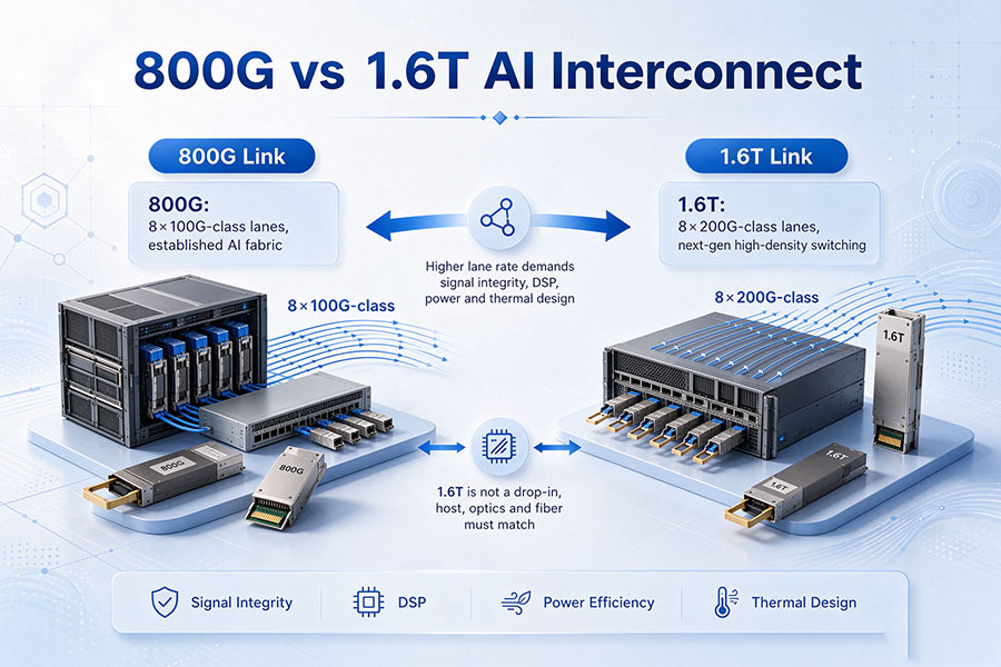
800G optical modules commonly use eight approximately 100G-class electrical lanes. The SerDes generation determines the electrical signaling capability between the switch ASIC and module. The Optical DSP handles additional module-side processing when the architecture requires it.
1.6T connectivity
1.6T optical interfaces commonly move toward eight approximately 200G-class electrical lanes. These interfaces require higher-bandwidth SerDes technology, improved channel design, and more demanding signal processing.
The host SerDes and Optical DSP must be designed for the same electrical and optical interface requirements. A higher SerDes lane rate alone does not guarantee that an optical module will support the corresponding data rate or transmission reach.
| Network Generation | Common Electrical Lane Configuration | SerDes Role | Optical DSP Role |
|---|---|---|---|
| 400G | 4 × 100G-class or 8 × 50G-class | Provides host electrical lanes | Performs module processing where required |
| 800G | 8 × 100G-class | Supports higher-rate electrical interfaces | Supports module-side signal conditioning and optical processing |
| 1.6T | 8 × 200G-class in common architectures | Supports next-generation high-speed electrical lanes | Handles the processing required by the specific optical implementation |
These are representative architecture examples rather than universal lane mappings. Actual configurations depend on the applicable Ethernet or optical interface standard and the transceiver design.
9. Electrical SerDes vs Coherent Optical DSP
The distinction between SerDes and Optical DSP becomes even clearer in coherent optical transmission. A coherent optical transceiver must process more than the electrical interface between the host and module. It must also recover information encoded in the amplitude and phase of the received optical signal.
A coherent receiver uses optical components such as a local oscillator laser, optical hybrid, balanced photodetectors, and TIAs to generate electrical signals. ADCs digitize these signals, and the coherent DSP performs advanced digital processing to recover the transmitted information.
Depending on the coherent architecture, DSP functions may include:
Chromatic dispersion compensation.
Polarization demultiplexing and polarization-mode dispersion compensation.
Frequency offset estimation and carrier recovery.
Phase recovery and phase-noise compensation.
Adaptive equalization and signal reconstruction.
Modulation and demodulation processing.
FEC processing where integrated into the coherent subsystem.
The host SerDes still provides the electrical interface to the coherent module. It does not replace the coherent DSP's optical signal-processing functions.
This is why coherent 400ZR, ZR+, and other long-distance optical systems require specialized DSP capabilities beyond ordinary host electrical serialization and deserialization.
10. Compatibility and System Design Considerations
SerDes and Optical DSP compatibility must be evaluated across the complete electrical and optical link. A transceiver's nominal data rate and physical form factor do not fully describe its electrical interface or processing architecture.
Important design considerations include:
SerDes lane rate: Confirm that the host ASIC supports the required electrical signaling rate and lane configuration.
Electrical interface: Verify the applicable host-to-module interface and its signal requirements.
Channel loss: Evaluate PCB insertion loss, return loss, connector discontinuities, and crosstalk.
Equalization capability: Confirm host and module equalization functions, especially for linear optical architectures.
DSP architecture: Identify whether the module uses a full DSP, partial retiming, or a linear signal path.
FEC configuration: Confirm the location and compatibility of PCS/FEC functions at both link endpoints.
Optical interface: Verify wavelength, modulation format, fiber type, connector, and transmission distance.
Power and cooling: Evaluate module power, host SerDes power, airflow, and thermal limits.
Platform interoperability: Validate the complete switch or NIC and transceiver combination.
A module with a DSP and a linear module may use the same OSFP or QSFP-DD form factor but have different electrical requirements. Compatibility must be established through the host interface specification, module datasheet, platform support, and actual system validation.
11. C-LIGHT Optical Transceiver Connectivity
High-speed optical connectivity requires coordinated operation between the host ASIC, SerDes, optical module, and fiber infrastructure. The choice of DSP-based or linear optical architecture affects the division of signal-processing responsibilities, but it does not change the need to match the optical interface and host platform.
C-LIGHT provides optical transceiver solutions for data center, enterprise, and telecommunications networks. The C-LIGHT Optical Transceiver portfolio provides a starting point for evaluating optical modules across different speeds and applications.
For 400G, 800G, and 1.6T deployments, module selection should account for host SerDes capability, electrical lane mapping, DSP architecture, optical reach, wavelength, fiber type, connector, power consumption, and thermal requirements.
Compatibility testing is particularly important when integrating third-party optical modules into switches and NICs. The complete electrical and optical link should be validated under the intended platform configuration.
For optical transceiver selection, platform compatibility, and customized connectivity requirements, Contact C-LIGHT.
12. Conclusion
SerDes and Optical DSP perform different but closely related roles in high-speed optical communication. SerDes converts parallel and serial electrical data and manages the electrical channel between the host ASIC and connected devices. Optical DSP performs additional signal processing within the optical transceiver, supporting electrical waveform conditioning, optical signal recovery, and advanced optical impairment compensation.
Their functions can overlap in areas such as equalization and clock recovery. Modern SerDes devices already include advanced signal-processing capabilities, while Optical DSPs may integrate their own SerDes interfaces. However, the two components are not interchangeable.
In conventional DSP-based optical modules, the host SerDes and module DSP share the signal-processing workload. In LPO architectures, more of that workload shifts to the host SerDes, reducing module processing overhead while increasing electrical channel and host compatibility requirements.
As networks advance from 400G to 800G and 1.6T, understanding the relationship between SerDes and Optical DSP is essential for selecting compatible transceivers, managing power consumption, maintaining signal integrity, and building reliable high-bandwidth optical networks.
 >

 >
 >
 >
 >
 >
 >
 >