TEL:+86 132 6656 7067





High-speed optical transceivers traditionally rely on digital signal processors (DSPs) to compensate for electrical and optical signal impairments. As data rates increase to 400G, 800G, and beyond, the power and thermal requirements of these processing circuits become increasingly important in high-density data center environments.
Linear Pluggable Optics (LPO) and linear receiver architectures offer alternative ways to distribute signal processing between the optical module and the host switch or network interface card (NIC). Both reduce reliance on conventional DSP processing, but they do not remove it in the same way. LPO uses linear operation on both transmit and receive paths, while a linear-receiver configuration can retain transmit-side retiming and remove DSP processing from the receive path.
Understanding this distinction helps network designers evaluate module power, signal integrity, latency, interoperability, and system-level performance.
1. What Is Linear Pluggable Optics (LPO)?
Linear Pluggable Optics is an optical transceiver architecture that removes the conventional DSP or retimer from the module's high-speed signal path. Instead of performing extensive digital signal processing inside the transceiver, LPO relies more heavily on the host switch ASIC or NIC SerDes to provide signal equalization and compensation.
A conventional retimed optical module processes electrical signals through a DSP before optical transmission and after optical reception. LPO changes this arrangement by using a more direct, linear electrical-to-optical and optical-to-electrical signal path.
A typical LPO module includes:
Optical transmitter: Converts the electrical input into an optical signal through the laser and modulation components.
Linear driver: Drives the optical modulator or light source without a conventional module DSP performing full transmit retiming.
Photodetector: Converts incoming optical signals into electrical signals.
Linear transimpedance amplifier (TIA): Amplifies the received electrical signal while preserving its waveform characteristics for the host receiver.
Host SerDes: Performs much of the equalization and signal conditioning normally distributed between the module and host.
Removing the module DSP can reduce module power consumption, heat generation, and processing latency. However, the host ASIC must have sufficient signal-processing capability to manage the complete electrical and optical channel.
2. What Is a Linear Receiver?
A linear receiver is a receiver-side architecture that amplifies and forwards the incoming electrical waveform without performing the full digital retiming and signal regeneration normally associated with a DSP-based receiver.
In an optical transceiver, the optical signal is first converted into an electrical signal by a photodetector. A transimpedance amplifier then converts the detector current into a usable voltage signal. In a linear receiver design, the amplified signal is passed toward the host SerDes, which performs the required receiver-side equalization and signal recovery.
The key characteristic is that the module receiver does not perform the conventional DSP-based retiming function. The host therefore assumes more responsibility for recovering the incoming signal.
3. LPO vs Linear Receiver: Understanding the Architecture
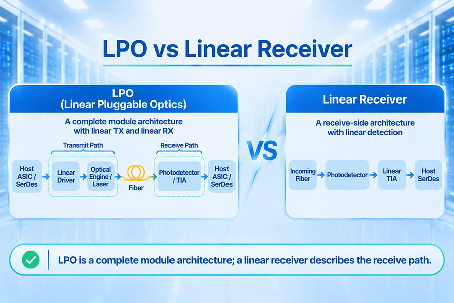
The main difference is the scope of linear operation. LPO describes a complete pluggable optical architecture with linear transmit and receive paths. A linear receiver describes only the receive-side signal path.
In practical optical module discussions, the comparison often refers to LPO versus an LRO-style module that combines a retimed transmitter with a linear receiver.
LPO Signal Path
In an LPO link, the host ASIC drives the optical module through a linear transmit path. The module converts the electrical signal into an optical signal without conventional DSP-based retiming. At the receiving end, the optical signal is converted back into an electrical waveform and passed through a linear receiver to the destination host.
Both ends rely heavily on host SerDes capabilities for signal conditioning and recovery.
Linear Receiver or LRO Signal Path
In an LRO-style architecture, the module retains transmit-side DSP or retiming while using a linear receive path. The transmitter therefore provides a retimed optical signal, while the receiving host performs more of the signal recovery work.
This arrangement offers a middle ground between a fully retimed module and a fully linear LPO link.
4. Key Differences Between LPO and Linear Receiver Architecture
| Comparison Factor | LPO | Linear Receiver / LRO |
|---|---|---|
| Architecture | Linear transmit and receive paths | Retimed transmit path and linear receive path |
| Transmit-side DSP | Removed from the module signal path | Retained for transmit-side processing |
| Receive-side DSP | Removed from the module signal path | Removed from the receive path |
| Signal conditioning | Primarily handled by host SerDes and linear module components | Shared between transmit-side module processing and host receiver |
| Module power | Generally lower | Generally higher than LPO but lower than a comparable fully retimed module |
| Module latency | Generally lower | Higher than LPO because transmit-side processing remains |
| Host requirements | High capability required on both transmit and receive sides | Strong receive-side host capability required |
| Signal integrity | Depends heavily on the complete end-to-end channel | Transmit-side retiming provides additional signal conditioning |
| Interoperability | Requires carefully validated host-module combinations | Can offer a compromise in interoperability and signal conditioning |
| Design objective | Minimize module power and processing latency | Reduce receiver-side DSP power while retaining transmit retiming |
These differences describe typical architecture behavior. Actual power savings, latency, reach, and interoperability depend on the module implementation, host SerDes, electrical channel, optical interface, and system configuration.
5. DSP Placement and Signal Processing
The location of digital signal processing is one of the most important distinctions between conventional retimed optics, LPO, and LRO.
In a traditional fully retimed module, the DSP performs signal conditioning on both transmit and receive paths. It can compensate for channel impairments, retime signals, and support functions such as equalization and forward error correction, depending on the module architecture.
In LPO, conventional module DSP processing is removed from both directions. The host ASIC or NIC takes on a larger share of the equalization and signal recovery tasks.
In LRO, transmit-side retiming remains inside the module, while the receive-side DSP function is removed. This reduces processing on one side without making the entire module fully linear.
| Signal Path | Fully Retimed Optics | LPO | LRO |
|---|---|---|---|
| Host to optical transmitter | Module DSP / retiming | Linear module path | Module DSP / retiming |
| Optical transmitter | DSP-driven electrical interface | Linear driver | DSP-driven electrical interface |
| Optical receiver | DSP-based receiver processing | Linear receiver | Linear receiver |
| Optical receiver to host | Retimed electrical output | Linear electrical output | Linear electrical output |
The exact division of equalization, clock recovery, and other signal-processing functions depends on the implementation. Removing a module DSP does not mean that all signal processing disappears from the system.
6. Power Consumption and Thermal Performance
Power efficiency is a major reason for the development of linear optical architectures. Conventional high-speed optical modules may require substantial power for DSP processing, signal conditioning, and optical conversion.
LPO removes the conventional DSP from the module signal path, which can reduce module power consumption and simplify thermal management. This is particularly attractive in high-density switches where hundreds of optical ports may operate simultaneously.
LRO retains transmit-side processing but removes the receive-side DSP function. Its power consumption is therefore generally between fully retimed optics and LPO, although the actual result depends on the implementation.
Power planning should consider more than the module specification. Important factors include:
Host ASIC and SerDes power consumption.
Module driver and TIA power requirements.
DSP power on the transmit side, where applicable.
Optical transmitter and receiver efficiency.
Switch airflow and cooling capacity.
Total system power across all active optical ports.
Because LPO transfers more signal-processing responsibility to the host, evaluating module power alone may not provide a complete picture of system-level energy efficiency.
7. Latency and Signal Recovery
Removing DSP-based retiming from the optical module can reduce the processing delay associated with the module. LPO therefore offers a lower-latency signal path compared with a fully retimed module using comparable interfaces.
LRO removes receive-side DSP processing but retains transmit-side retiming. Its module processing latency is generally higher than LPO, while potentially lower than a fully retimed architecture.
However, end-to-end latency is determined by the complete link, including:
Host ASIC SerDes processing.
Electrical channel characteristics.
Module driver and receiver circuitry.
Optical transmission and propagation distance.
DSP or retimer processing where present.
FEC implementation and system-level data handling.
For AI clusters and high-performance computing environments, small differences in link latency can matter when large numbers of communication operations occur across multiple accelerators. System-level benchmarking is therefore more useful than evaluating module latency in isolation.
8. Signal Integrity and Host Compatibility
Linear optical architectures place greater importance on electrical channel quality and host SerDes performance. In a fully retimed module, the DSP can compensate for a wider range of signal impairments. When that processing is removed, the host and module must operate together as a carefully engineered end-to-end channel.
For LPO, both transmit and receive paths require sufficient host-side signal conditioning. For LRO, the receive-side host still needs to recover a linear signal, but transmit-side retiming provides additional conditioning before optical transmission.
Key engineering considerations include:
Host ASIC transmit equalization capability.
Host receiver equalization and decision feedback equalization support.
PCB trace length and insertion loss.
Connector and module electrical interface performance.
Signal reflections, crosstalk, and channel noise.
Optical link budget and receiver sensitivity.
BER performance under expected operating conditions.
Interoperability testing is particularly important because two modules with the same nominal data rate may not perform identically when connected to different host ASICs or electrical channel designs.
9. Reach and Application Considerations
Linear architectures are especially relevant to high-speed data center connections where power consumption and latency are important design priorities. However, removing DSP processing reduces the amount of signal compensation available inside the module, making link reach and channel quality important considerations.
Fully retimed modules generally provide greater flexibility for challenging electrical channels and a broader range of deployment conditions. LPO is more dependent on optimized host electrical interfaces and validated link configurations. LRO provides an intermediate approach by retaining transmit-side retiming.
| Application Requirement | Architecture to Evaluate | Primary Consideration |
|---|---|---|
| Lowest module power | LPO | Host SerDes capability and end-to-end channel quality |
| Reduced receive-side DSP power | LRO | Linear receiver compatibility and receive-channel margin |
| Strong signal conditioning in both directions | Fully retimed optics | DSP power, thermal requirements, and link flexibility |
| High-density short-reach data center links | LPO or LRO | Validated switch and module combinations |
| More challenging channel conditions | Fully retimed optics or validated LRO | Signal integrity and available compensation |
No architecture has a universal reach advantage across all products. Supported distances must be evaluated using the actual optical specification, fiber type, host electrical channel, and link validation results.
10. LPO and Linear Receiver Applications in 400G and 800G Networks
At 400G and 800G, the number of high-speed electrical lanes and the signal integrity requirements make DSP architecture an important part of optical module design.
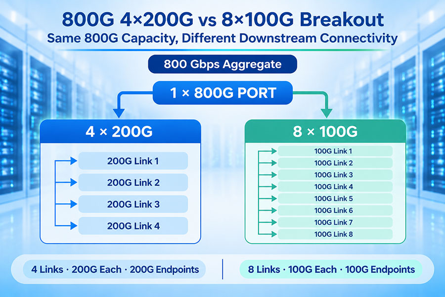
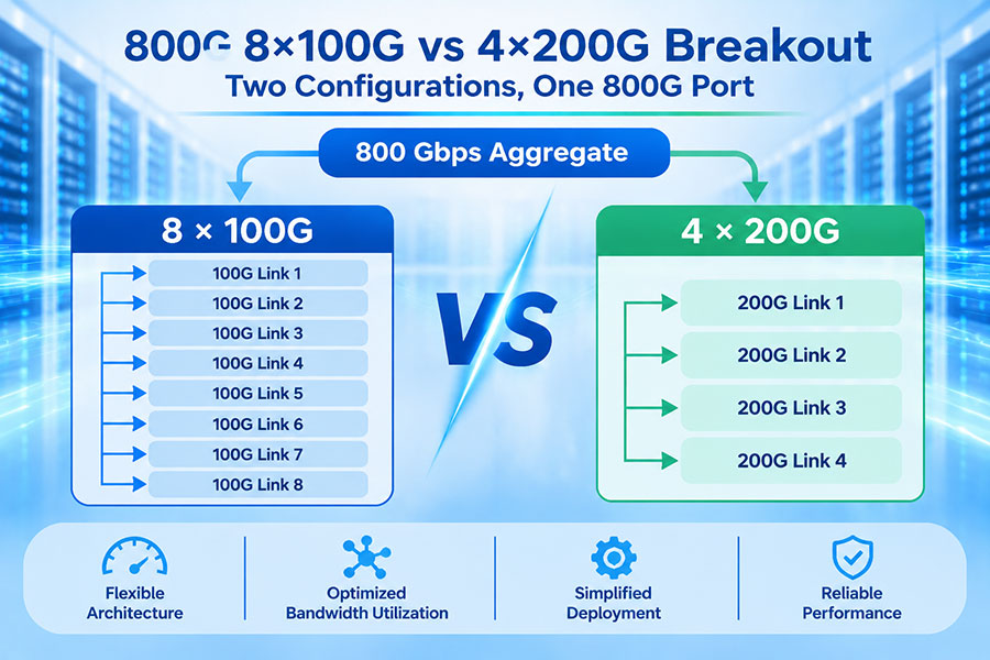
For example, an 800G optical interface may use eight electrical lanes operating at approximately 100G per lane, or four lanes operating at approximately 200G per lane, depending on the host interface and module architecture. PAM4 signaling is widely used in these high-speed interfaces.
As lane rates increase, the electrical channel becomes more challenging to manage. Host SerDes performance, PCB design, module circuitry, and optical link characteristics must be considered together.
In 400G and 800G environments, LPO and LRO are relevant to short-reach data center connectivity where reducing power and latency can provide system-level benefits. Their suitability depends on whether the switch ASIC or NIC can support the required linear channel performance.
For next-generation 1.6T platforms, the same architectural questions become even more important as electrical lane rates, optical density, power budgets, and thermal requirements continue to evolve.
11. Testing and Validation Requirements
Linear optical modules require comprehensive validation because more of the signal-processing responsibility is shared across the host and optical link. Testing should evaluate the complete system rather than the module alone.
Important validation areas include:
BER testing: Measures bit error performance under defined operating conditions.
Eye diagram analysis: Evaluates signal quality, timing margin, and amplitude characteristics.
Receiver sensitivity: Verifies the minimum optical input level required to meet the specified performance.
Transmitter performance: Checks optical output characteristics and signal quality.
Electrical channel validation: Measures insertion loss, return loss, and other relevant channel characteristics.
Interoperability testing: Validates operation with the intended switch ASIC, NIC, firmware, and optical module combinations.
Thermal testing: Evaluates module and host behavior across the intended operating temperature range.
Testing should use the relevant interface specifications and system requirements. A module that passes standalone optical tests may still require additional host-level validation before deployment in an LPO or LRO configuration.
12. How to Choose Between LPO and Linear Receiver Architecture
The choice depends on the system's power targets, host SerDes capabilities, signal integrity margin, deployment distance, and interoperability requirements.
When to Consider LPO
The switch ASIC or NIC has sufficiently capable transmit and receive SerDes.
The electrical channel is carefully designed and validated.
Lower module power and latency are major priorities.
The deployment uses compatible short-reach optical links.
The complete host-to-host link can meet the required BER and reliability targets.
When to Consider LRO
Reducing receive-side DSP power is a priority.
Transmit-side retiming is desirable for signal conditioning.
The host receiver can handle the linear receive signal.
A compromise between fully retimed optics and LPO is preferred.
The module and host combination has been validated for the intended application.
When to Retain Fully Retimed Optics
The host electrical channel requires additional signal compensation.
Broad interoperability is a major requirement.
The deployment has more challenging channel or reach conditions.
System design prioritizes signal conditioning over minimum module power.
13. C-LIGHT Optical Connectivity for High-Speed Data Centers
The transition toward LPO and linear receiver architectures is part of a broader shift in high-speed optical connectivity. As data center switches move toward 400G, 800G, and 1.6T interfaces, optical module selection must account for electrical interface design, host compatibility, thermal performance, and link-level validation.
C-LIGHT provides optical transceiver and fiber connectivity products for data center and high-speed networking applications, including:
400G OSFP optical transceivers: High-speed optical connectivity options for compatible data center switching platforms. View 400G OSFP Products.
800G OSFP optical transceivers: Optical connectivity for high-bandwidth data center and AI network applications. View 800G OSFP Products.
1.6T OSFP-RHS products: Next-generation optical connectivity for compatible high-density switching systems. View 1.6T OSFP-RHS Products.
DAC and AOC assemblies: Short-reach connectivity solutions for suitable server and switch configurations. View DAC and AOC Products.
MPO/MTP fiber assemblies: High-density fiber connectivity for parallel optical interfaces and structured cabling. View MPO/MTP Products.
When evaluating LPO or LRO solutions, customers should confirm the exact module architecture rather than relying only on the form factor or data rate. Host compatibility, transmit and receive signal paths, optical specifications, and validation results are essential to selecting a suitable product.
C-LIGHT provides optical transceiver and fiber connectivity solutions for data center and AI networking applications. Contact our team to discuss module specifications, host compatibility, and optical link requirements.
14. Conclusion
LPO and linear receiver architectures reduce the amount of conventional DSP processing performed inside optical transceivers, but they represent different levels of signal-path linearity.
LPO removes conventional module DSP processing from both transmit and receive paths, relying heavily on host SerDes capabilities. A linear-receiver architecture, commonly implemented as LRO or RTLR, retains transmit-side retiming while using a linear receive path.
LPO generally offers the lowest module power and processing latency, while LRO provides a compromise between power efficiency and transmit-side signal conditioning. Fully retimed optics remain relevant where additional signal compensation and broader interoperability are important.
For 400G, 800G, and future 1.6T data center networks, the best architecture depends on the complete electrical and optical channel. Host capability, signal integrity, thermal performance, and interoperability testing should all be considered before selecting a linear optical solution.
 >

 >
 >
 >
 >
 >
 >
 >