TEL:+86 132 6656 7067





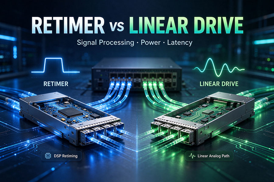
High-speed optical links require electrical signals to travel between a host ASIC and an optical transmitter or receiver without losing the signal quality needed for reliable data transmission. Traditional retimed optics use dedicated signal-processing circuitry to recover and regenerate electrical signals inside the module. Linear Drive Optics takes a different approach, using linear analog components to maintain a more direct connection between the host SerDes and optical front end. The choice affects module power, latency, electrical channel design, and system interoperability.
1. What Is a Retimer?
A retimer is an active electronic device that receives a high-speed electrical data signal, recovers its timing, and retransmits a regenerated signal. Its main purpose is to reduce the accumulation of timing-related signal degradation as data travels through an electrical channel.
High-speed signals passing through PCB traces, connectors, cables, and other electrical interfaces experience insertion loss, reflections, crosstalk, and timing distortion. A retimer helps restore the signal at an intermediate point so that the next section of the link receives a cleaner electrical signal.
In optical transceivers, retiming is commonly implemented as part of a DSP-based signal-processing architecture. Depending on the design, the DSP may perform equalization, clock and data recovery, signal conditioning, and other functions in addition to retiming.
Typical retimed optical signal path
Host ASIC SerDes → Module DSP / Retimer → Optical Driver → Laser → Fiber
Receive direction:Fiber → Photodetector → TIA → Module DSP / Retimer → Host ASIC SerDes
This arrangement gives the optical module responsibility for a substantial part of the electrical signal-conditioning process. The host and optical front end are separated by a module-level processing stage rather than relying entirely on one continuous linear electrical channel.
2. What Is Linear Drive Optics?
Linear Drive Optics (LDO) uses a more direct electrical interface between the host SerDes and optical front end. Instead of relying on a conventional module DSP or retimer to recover and regenerate the signal, the architecture uses linear analog components to drive the optical transmitter and process the received electrical waveform.
A linear optical module typically includes a linear driver, laser or modulator, photodetector, and linear transimpedance amplifier (TIA). These are active components. Linear Drive does not mean that the optical module is passive or contains no electronics.
The main architectural change is the removal of conventional module-level DSP retiming from the relevant signal path. More of the equalization and signal-conditioning responsibility moves to the host ASIC SerDes.
Typical linear-drive signal path
Host ASIC SerDes → Linear Driver → Laser / Modulator → Fiber
Receive direction:Fiber → Photodetector → Linear TIA → Host ASIC SerDes
Linear Drive is an architectural approach rather than one specific module form factor. Linear Pluggable Optics (LPO) applies this principle to removable front-panel optical modules. Linear-drive concepts can also be used in other optical integration approaches, depending on the system design.
3. Retimer vs Linear Drive: Main Technical Differences
| Technical Factor | Retimed Optics | Linear Drive Optics |
|---|---|---|
| Signal Processing | Uses module-level DSP or retiming circuitry | Uses a more direct linear analog signal path |
| Signal Recovery | Module recovers and regenerates the electrical signal | Greater reliance on host SerDes signal recovery and equalization |
| Transmit Interface | DSP or retimer processes the host electrical signal before optical conversion | Linear driver connects the electrical input to the optical transmitter |
| Receive Interface | Module DSP or retimer processes the received electrical signal | Linear TIA delivers the received waveform toward the host |
| Module Power | Generally higher because of additional digital processing | Potentially lower due to simplified module electronics |
| Processing Latency | Includes module retiming and DSP processing | Can reduce module processing latency |
| Host SerDes Dependency | More signal conditioning is handled inside the module | Greater responsibility for host SerDes equalization and signal recovery |
| Electrical Channel | Module retiming separates portions of the electrical channel | Combined host-to-module channel performance is more critical |
| Interoperability | Established retimed module interfaces support broad deployment | Requires careful host and module electrical qualification |
| Thermal Design | Includes heat from module DSP and supporting circuits | Can reduce module heat generation, while host SerDes power remains relevant |
| Typical Priority | Signal conditioning and electrical channel isolation | Lower module power, lower processing latency, and simplified signal paths |
These are general architectural differences. Actual power, latency, and signal performance depend on the data rate, DSP implementation, host ASIC, module design, and electrical channel.
4. How Retiming Changes the Electrical Signal Path
The primary purpose of a retimer is to restore signal timing and retransmit data across a new electrical segment. This is especially useful when the original signal has traveled through a channel with significant insertion loss or timing degradation.
A retimed optical module creates a signal-processing boundary between the host interface and optical front end. The module receives the electrical signal, performs the required recovery and conditioning, and generates a new signal for the optical transmitter. On the receive side, it processes the electrical output from the photodetector and TIA before delivering data to the host.
Linear Drive removes this conventional module-level regeneration stage. The host SerDes must therefore be capable of handling the combined electrical channel characteristics and the linear behavior of the optical module.
This does not mean that the linear architecture has no equalization. Host SerDes circuits can include transmitter equalization, receiver equalization, and other signal-processing functions. The difference is where those functions are implemented and how much responsibility is assigned to the host.
5. Power Consumption and Energy Efficiency
DSP and retiming circuitry can contribute significantly to the power consumption of high-speed optical modules. As optical interfaces move toward higher lane rates, the processing requirements of module electronics become an important part of the total power budget.
Linear Drive reduces the need for conventional module-level DSP processing. By using a linear driver and TIA, a suitable design can lower module power consumption and reduce heat generated inside the transceiver.
The total system power calculation is more complex. A linear architecture places greater demands on the host SerDes and may require additional host-side equalization or calibration. Therefore, lower module power does not automatically translate into an identical reduction in switch power.
| Power Factor | Retimed Optics | Linear Drive Optics |
|---|---|---|
| Module DSP | Present in conventional fully retimed implementations | Conventional module DSP retiming is removed from the relevant paths |
| Driver and TIA | Required | Required, typically with linear operation |
| Host SerDes | Performs host-side signal processing | Handles a greater share of channel equalization and recovery |
| Module Heat | Includes DSP-related thermal load | Potentially reduced module thermal load |
| System-Level Power | Includes module DSP and host SerDes power | Includes linear module power and host SerDes requirements |
6. Latency and Signal Integrity
A retimer adds a signal-processing stage to the electrical path. Its clock recovery and data regeneration functions contribute processing latency, although the exact delay depends on the device and implementation.
Linear Drive can reduce this processing overhead because it avoids conventional module-level DSP retiming. This is useful in applications where low-latency connectivity is important, including high-performance computing and AI cluster networks.
However, fewer processing stages do not automatically produce a more reliable link. Linear systems require sufficient signal margin across the complete electrical channel. PCB insertion loss, return loss, connector discontinuities, crosstalk, and host equalization settings can all affect performance.
Retimed optics provide a degree of signal isolation between the host and optical front end. Linear Drive trades some of that isolation for a simpler module signal path. The correct choice depends on whether the host platform can reliably manage the resulting electrical channel.
7. Retimed Optics, Linear Drive, LPO, and LRO
These terms are related but describe different aspects of optical interconnect architecture. Retimed optics describes a signal-processing arrangement. Linear Drive describes a way of operating the electrical interface. LPO and LRO identify particular pluggable optical implementations.
| Architecture | Transmit Path | Receive Path | General Description |
|---|---|---|---|
| Fully Retimed Optics | Retimed | Retimed | Module performs signal processing on both directions |
| LPO | Linear | Linear | Pluggable optical module without conventional DSP retiming on either data path |
| LRO / RTLR | Retimed | Linear | Retimed transmit with linear receive |
LPO is a common implementation of Linear Drive in front-panel optical modules. It uses linear analog components and relies more heavily on the host SerDes.
LRO, often described as Retimed Transmit and Linear Receive (RTLR), retains transmit-side retiming while using a linear receive path. It provides an intermediate architecture for applications that want some of the benefits of linear reception without removing all module-level retiming.
Linear Drive should not be treated as another name for LPO in every context. The term can describe a broader design approach, including optical engines in different physical integration arrangements.
8. Host ASIC and SerDes Compatibility
Host compatibility is one of the most important considerations when deploying Linear Drive optics. In a retimed design, the module performs more signal recovery internally. In a linear design, the host ASIC must support the electrical channel presented by the module.
The host SerDes needs adequate equalization capability, signal margin, and operating flexibility. Its performance must be evaluated together with the PCB layout, connector, module electrical interface, and optical front-end characteristics.
Key engineering checks
ASIC support: Confirm that the host switch or NIC supports the intended linear or retimed architecture.
SerDes capability: Verify supported lane rates, transmitter equalization, receiver equalization, and signal recovery functions.
Electrical channel: Evaluate insertion loss, return loss, crosstalk, PCB trace length, and connector performance.
Module linearity: Confirm that the driver and TIA meet the required electrical interface performance.
FEC behavior: Verify that the host and link configuration use compatible FEC requirements.
Optical interface: Check wavelength, fiber type, connector, transmission distance, and optical power budget.
System validation: Test the actual switch, module, firmware, and link configuration under the intended operating conditions.
9. Applications in AI Data Centers and High-Speed Networks
AI data centers use large numbers of high-speed optical links to connect GPU servers, switches, and other network equipment. As port speeds and aggregate bandwidth increase, the power consumed by optical modules becomes an important part of the overall network energy budget.
Retimed optics remain useful where electrical channel compensation, signal conditioning, and deployment flexibility are priorities. Their module-level DSP provides a processing boundary that can simplify some host-to-module integration challenges.
Linear Drive is attractive in systems where the host ASIC has sufficiently capable SerDes circuitry and the electrical channel can be carefully controlled. Reducing module DSP processing can help lower optical module power and latency, particularly across large numbers of short-reach links.
Neither approach is universally suitable for every data center link. Reach, lane rate, electrical loss, optical performance, system architecture, and maintenance requirements all influence the selection.
10. C-LIGHT Optical Transceiver Solutions
Retimed and linear-drive architectures change how signals are processed inside an optical interconnect, but the fundamental optical-link requirements remain important. Network engineers still need to select the appropriate data rate, wavelength, fiber type, connector, transmission distance, and optical power budget.
C-LIGHT offers optical transceiver solutions for data center, enterprise, and telecommunications networks. The C-LIGHT Optical Transceiver portfolio provides a product entry point for high-speed optical connectivity requirements.
When selecting 400G, 800G, or other high-speed transceivers, customers should verify the actual module signal-processing architecture rather than assuming that every product with the same form factor supports Linear Drive or LPO operation.
For platform compatibility, customized optical connectivity, and application-specific transceiver requirements, Contact C-LIGHT.
11. Conclusion
Retimer-based optics and Linear Drive Optics use different approaches to managing high-speed electrical signals. Retimed architectures recover and regenerate signals within the optical module, helping isolate electrical channel impairments and providing a more established host-module interface. Linear Drive removes conventional module-level DSP retiming from the relevant paths and relies more heavily on the host SerDes.
Linear Drive can reduce module power and signal-processing latency, making it attractive for suitable AI and high-performance data center networks. Its performance depends on the electrical channel, host SerDes capability, module linearity, and system-level validation.
Retimed optics remain valuable where signal conditioning and interoperability are important. Linear Drive is a compelling option when the host and optical module are designed to operate as a qualified linear system. The decision should be based on the complete electrical and optical link rather than module power or form factor alone.
 >

 >
 >
 >
 >
 >
 >
 >