TEL:+86 132 6656 7067





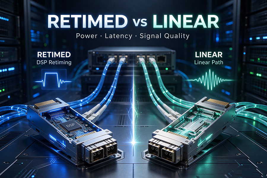
High-speed optical connectivity depends on more than the optical transmitter, receiver, and fiber interface. The way electrical signals are processed inside an optical module directly affects power consumption, latency, signal integrity, and host compatibility. Retimed and linear optical modules represent two different approaches to this signal-processing challenge. Retimed designs use module-level digital signal processing to recover and regenerate electrical signals, while linear designs simplify the module electronics and rely more heavily on the host ASIC's SerDes.
1. What Is a Retimed Optical Module?
A retimed optical module uses a DSP or dedicated retiming circuitry to process high-speed electrical signals between the host system and optical components. The module performs signal conditioning and clock recovery functions to help restore signal quality before transmitting or delivering data across the electrical interface.
In a conventional fully retimed architecture, signal processing is performed on both the transmit and receive paths. On the transmit side, the module receives an electrical signal from the host, processes it, and drives the optical transmitter. On the receive side, the photodetector and transimpedance amplifier convert the incoming optical signal into an electrical signal, which is then processed before being delivered to the host.
This arrangement creates a more clearly defined electrical interface between the host and the optical module. The module takes responsibility for a substantial part of the signal-conditioning process rather than requiring the host to manage the entire electrical path.
Typical retimed signal path
Host ASIC SerDes → Module DSP/CDR → Optical Driver → Laser → Optical Fiber
Receive direction:Optical Fiber → Photodetector → TIA → Module DSP/CDR → Host ASIC SerDes
The exact internal implementation varies by module generation and design. Some products integrate multiple signal-processing functions into one DSP, while others use additional analog or clock-recovery circuitry. The key architectural characteristic is that the module performs retiming rather than operating as a purely linear electrical interface.
2. What Is a Linear Optical Module?
A linear optical module uses a simpler electrical signal path without conventional module-level DSP retiming in the relevant transmit and receive paths. Instead of fully recovering and regenerating the electrical signal inside the module, it uses linear analog components to connect the host electrical interface more directly to the optical transmitter and receiver.
Typical linear modules use a linear laser driver on the transmit side and a linear transimpedance amplifier (TIA) on the receive side. The host ASIC SerDes performs more of the equalization and signal-conditioning work that would otherwise be handled by the module DSP.
Typical linear signal path
Host ASIC SerDes → Linear Driver → Laser → Optical Fiber
Receive direction:Optical Fiber → Photodetector → Linear TIA → Host ASIC SerDes
Linear does not mean that the module contains no active electronics or signal conditioning. The laser driver, TIA, gain control, and analog equalization circuits may still be present. The distinction is that the conventional digital retiming function is removed from the relevant module signal path.
Linear Pluggable Optics (LPO) is the best-known example of this architecture. It retains the mechanical advantages of a pluggable optical transceiver while shifting more electrical signal-processing responsibility to the host.
3. Retimed vs Linear Optical Modules: Main Differences
| Technical Factor | Retimed Optical Module | Linear Optical Module |
|---|---|---|
| Signal Processing | Uses module-level DSP or retiming circuitry | Uses a more direct linear electrical signal path |
| Transmit Path | Electrical signal is processed and retimed before optical conversion | Linear driver drives the optical transmitter |
| Receive Path | Received electrical signal is processed and retimed inside the module | Linear TIA delivers the signal toward the host receiver |
| DSP Placement | Inside the optical module for the retimed paths | More processing responsibility is placed on the host ASIC |
| Module Power | Generally higher due to module DSP processing | Potentially lower due to simplified module electronics |
| Latency | Includes module signal-processing latency | Can reduce module processing latency |
| Host Dependency | Relatively more signal conditioning is performed inside the module | Greater dependence on host SerDes and electrical-channel performance |
| Signal Integrity | Module retiming helps isolate the host and optical electrical channels | End-to-end electrical channel quality becomes more critical |
| Interoperability | Generally offers a more established host-module interface model | Requires carefully qualified host and module combinations |
| Diagnostics | May provide DSP-related signal monitoring and diagnostics | Module-level DSP diagnostics may be unavailable; host and system telemetry become more important |
| Typical Application | Broad data center, enterprise, telecom, and long-reach applications | Suitable high-speed, short-reach, power-sensitive systems |
These are general architectural tendencies, not universal performance guarantees. Actual power, latency, interoperability, and diagnostic capabilities depend on the module design, host ASIC, electrical interface, optical specification, and system implementation.
4. DSP Retiming and Host SerDes Responsibilities
The most important difference between retimed and linear modules is where electrical signal recovery and equalization take place. A high-speed electrical signal can experience attenuation, reflections, crosstalk, and timing distortion as it travels through PCB traces, connectors, and module interfaces.
A retimed module uses its internal signal-processing circuitry to recover and regenerate the signal. This provides a degree of separation between the host electrical channel and the optical component interface. The host does not need to compensate for every impairment across the complete path to the optical driver or receiver.
A linear module removes much of this internal processing. The host SerDes must therefore handle a more demanding electrical channel, including the effects of the host PCB, connector, module interface, and linear analog circuitry.
The module performs more signal recovery and regeneration, helping isolate electrical channel impairments on either side of the module.
The host and module operate through a more direct linear interface, making host SerDes capability and channel quality central to link performance.
This is why a linear module cannot automatically replace a retimed module simply because both have the same data rate, connector, and mechanical form factor. The host electrical interface must support the intended linear architecture.
5. Power Consumption and Energy Efficiency
DSP processing is an important contributor to the power consumption of high-speed optical modules. As data rates increase, digital signal processing, clock recovery, equalization, and associated circuitry can account for a significant portion of module power.
Linear modules reduce this internal processing burden by using simpler analog circuitry. In suitable systems, this can lower module power consumption and reduce the amount of heat generated inside the optical module.
However, module power alone does not determine total system energy efficiency. A linear architecture may require more capable host SerDes circuitry, additional equalization resources, or more demanding electrical-channel design. These factors should be included when evaluating the total power of a switch or network platform.
| Power Consideration | Retimed Module | Linear Module |
|---|---|---|
| Module DSP Power | Required for retimed signal paths | Conventional module DSP retiming is removed from the relevant paths |
| Analog Circuitry | Driver, TIA, and supporting circuits | Linear driver, TIA, and supporting circuits |
| Host SerDes Workload | More limited by the module's signal-conditioning boundary | Greater equalization and signal-conditioning responsibility |
| Thermal Profile | More heat generated within the module by DSP processing | Potentially lower module heat generation |
| System-Level Evaluation | Include module DSP and host SerDes power | Include linear module power and additional host SerDes requirements |
6. Latency and Signal Quality
Retiming introduces additional signal-processing stages. DSP operations, clock recovery, equalization, and associated internal processing contribute to module latency. For applications that are sensitive to link latency, reducing these processing stages can be beneficial.
Linear modules can provide a shorter signal-processing path because they avoid conventional module DSP retiming. This makes them attractive for latency-sensitive AI and high-performance computing interconnects.
However, lower module latency does not automatically mean better end-to-end link performance. A linear link still needs sufficient signal margin, stable operation, and acceptable bit error rate. If the host electrical channel is poorly designed or insufficiently equalized, the link may experience degraded signal quality despite having fewer processing stages.
Retimed modules generally provide greater flexibility in managing electrical signal impairments because the module performs more recovery and regeneration. Linear modules exchange some of that isolation for lower processing complexity.
7. Retimed, LPO, and LRO: Understanding the Three Architectures
Retimed and linear are broad descriptions of signal-processing approaches. Within pluggable optics, three configurations are particularly relevant: fully retimed optics, Linear Pluggable Optics (LPO), and Linear Receive Optics (LRO).
| Architecture | Transmit Path | Receive Path | Signal-Processing Arrangement |
|---|---|---|---|
| Fully Retimed Optics | Retimed | Retimed | Module DSP/retiming on both directions |
| LPO | Linear | Linear | No conventional module DSP retiming on either path |
| LRO / RTLR | Retimed | Linear | Retimed transmit with linear receive |
LRO is often described as a half-retimed architecture. It retains transmit-side retiming while using a linear receive path. This provides an intermediate signal-processing arrangement between fully retimed optics and LPO.
The distinction is important when evaluating specifications. A product described as linear receive optics is not necessarily a fully linear LPO module. Engineers should check both transmit and receive paths rather than relying on a general label such as DSP-free or retimerless.
8. Compatibility and Interoperability Considerations
Retimed and linear optical modules may use familiar form factors such as OSFP and QSFP-DD, but mechanical compatibility does not establish electrical or functional compatibility. A module may physically fit into a switch cage while still being unsupported by the host platform.
Retimed modules generally provide a more established electrical boundary between the host and optical subsystem. This can make deployment across qualified platforms more straightforward, although the exact module specification and host compatibility requirements must still be checked.
Linear modules require closer coordination between the optical module and the host SerDes. Electrical channel loss, equalization capability, transmitter settings, receiver sensitivity, signal margin, and FEC behavior all influence whether a link operates reliably.
Key compatibility checks
Host ASIC: Confirm that the switch or NIC ASIC supports the required linear or retimed interface.
Electrical channel: Check PCB insertion loss, return loss, crosstalk, connector characteristics, and channel reach.
SerDes capability: Verify the host's transmitter and receiver equalization functions and supported operating modes.
Optical specification: Confirm wavelength, fiber type, connector, reach, and optical power budget.
FEC configuration: Ensure that host and link-layer FEC requirements are aligned.
Thermal and power limits: Check module power class, cooling capability, and chassis restrictions.
Interoperability testing: Validate the actual host, module, firmware, and link configuration before deployment.
9. Where Retimed and Linear Modules Are Used
Retimed optical modules
Retimed modules are widely suited to network environments that prioritize signal conditioning, interoperability, and flexible deployment. They are used in data center switching, enterprise networking, telecom transport, and other high-speed optical links where the host electrical channel may not be optimized for direct linear operation.
Linear optical modules
Linear modules are particularly relevant to short-reach, high-density data center connections where power and latency are major design considerations. AI clusters and high-performance computing networks are potential applications because they require large numbers of high-speed optical links and place significant pressure on system power budgets.
Their deployment depends on the capabilities of the host ASIC and the quality of the electrical design. A linear architecture is most suitable when the switch platform, module, and electrical channel have been engineered and validated as a complete system.
10. C-LIGHT Optical Transceiver Solutions
The choice between retimed and linear optical architectures does not change the basic optical-link requirements. Data rate, transmission distance, wavelength, fiber type, connector interface, optical power budget, and host compatibility remain essential selection factors.
C-LIGHT provides optical transceiver solutions for data center, enterprise, and telecommunications applications. Relevant product families can be found in the C-LIGHT Optical Transceiver portfolio, including high-speed optical modules for 400G and 800G network connectivity.
When evaluating a transceiver for a retimed or linear application, customers should confirm the module's actual DSP architecture and the host platform's supported electrical interface. A conventional 400G or 800G optical transceiver should not be assumed to support LPO simply because it uses the same form factor or optical standard.
For customized optical connectivity requirements, module compatibility validation, and application-specific solutions, Contact C-LIGHT.
11. Conclusion
Retimed and linear optical modules differ primarily in where high-speed electrical signal processing takes place. Retimed modules use internal DSP or retiming circuitry to recover and regenerate signals, providing greater electrical-channel isolation and a more established host-module interface model. Linear modules simplify the internal signal path, reduce conventional module DSP processing, and rely more heavily on the host SerDes.
Linear optics can reduce module power and processing latency, making it attractive for power-sensitive AI and data center networks. However, it requires careful host electrical-channel design, signal-integrity validation, and interoperability testing.
Fully retimed optics, LPO, and LRO each provide a different balance of signal conditioning, power, latency, and host dependency. The correct choice depends on the complete system architecture rather than the optical module's data rate or form factor alone.
 >

 >
 >
 >
 >
 >
 >
 >