TEL:+86 132 6656 7067





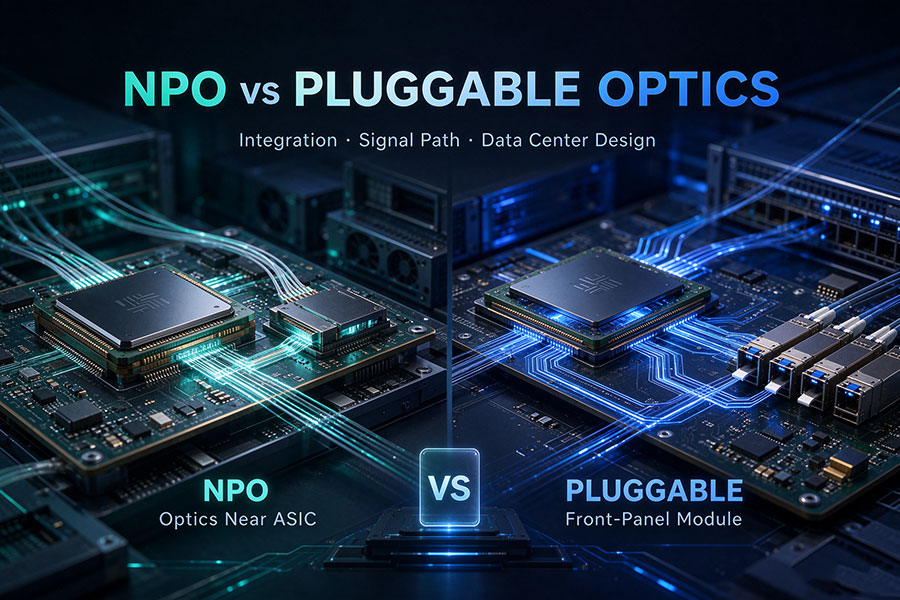
As switch ASIC bandwidth increases, the electrical connection between the switching chip and optical interfaces becomes a major consideration in data center hardware design. Traditional pluggable optics place transceivers at the front panel, requiring high-speed electrical signals to travel across the host board. Near-Packaged Optics (NPO) moves optical engines closer to the switch ASIC, reducing the electrical distance while retaining a separate optical subsystem.
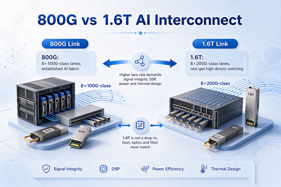
This architectural change is particularly relevant to AI data centers, where 800G and 1.6T network interfaces increase demands on signal integrity, port density, power efficiency, and cooling. NPO offers a different integration approach from conventional pluggable transceivers, but it also changes how optical components are assembled, accessed, tested, and maintained.
The central distinction is physical integration: pluggable optics prioritize front-panel accessibility and replaceability, while NPO prioritizes shorter electrical connections between the switch ASIC and optical engines.
1. What Are Pluggable Optics?
Pluggable optics are conventional optical transceiver modules installed in cages or ports located along the front panel of network equipment. The module converts electrical signals from the switch ASIC into optical signals for transmission over fiber, and converts incoming optical signals back into electrical signals.
Common pluggable form factors include:
SFP and SFP28: Used in lower-speed Ethernet and other optical networking applications.
QSFP28: Commonly used for 100G optical interfaces.
QSFP-DD: Supports high-density 400G and selected 800G applications.
OSFP: Designed for high-speed networking, including 800G and 1.6T implementations.
In a conventional architecture, the switch ASIC communicates with the front-panel transceiver through electrical traces on the package substrate and printed circuit board (PCB). Depending on the implementation, the electrical channel may require retiming and signal conditioning within the optical module.
Simplified architecture. The electrical path and signal-processing functions depend on the switch and transceiver implementation.
The main advantage is serviceability. A failed transceiver can generally be removed and replaced without replacing the entire switch or disturbing unrelated optical ports. Operators can also select different optical modules according to reach, wavelength, fiber type, and network application.
However, placing optical modules at the front panel creates a relatively long electrical path between the switch ASIC and the optical interface. As electrical lane rates increase, this channel becomes more difficult to manage because of insertion loss, reflections, crosstalk, and other signal-integrity limitations.
2. What Is Near-Packaged Optics (NPO)?
Near-Packaged Optics is an optical integration architecture that places optical engines close to the switch ASIC, typically on a shared high-performance substrate or interposer, while keeping the optical engines physically separate from the ASIC package itself.
Unlike front-panel pluggable transceivers, NPO does not rely on a long high-speed electrical connection extending across the main PCB to the equipment's front panel. The shorter electrical connection helps reduce channel loss and the signal-conditioning burden associated with long electrical traces.
A typical NPO implementation includes:
Switch ASIC: Performs packet switching and network processing.
Electrical engine: Contains the electronic circuitry required to drive and receive high-speed signals.
Photonic integrated circuit (PIC): Performs optical functions such as modulation and photodetection.
Optical engine: Integrates the relevant optical and electrical components for signal conversion.
Fiber interface: Connects the optical engine to the external fiber network.
Thermal structure: Provides heat dissipation for the ASIC and nearby optical components.
Conceptual NPO arrangement. The optical engine remains a separate component near the ASIC rather than sharing its package.
In NPO designs, the optical engine and switch ASIC can be developed and tested as separate components before being assembled onto the common substrate. This provides a different integration and manufacturing approach from CPO, where the optical engine is integrated within the same package architecture as the ASIC.
NPO implementations vary across vendors and industry proposals. The exact substrate, socket arrangement, optical-engine design, electrical interface, and maintenance model should be verified for each platform.
3. NPO vs Pluggable Optics: Key Technical Differences
Both architectures provide optical connectivity for high-speed switches, but their physical placement creates different electrical, mechanical, and operational characteristics.
| Technical Dimension | Pluggable Optics | Near-Packaged Optics |
|---|---|---|
| Optical engine location | Front-panel transceiver cage | Close to the switch ASIC on a shared substrate or interposer |
| Electrical path | Extends through the host package and PCB to the front panel | Shorter connection between ASIC and optical engine |
| ASIC integration | Separate from the front-panel module | Near the ASIC, but not necessarily in the same package |
| Optical interface | Front-panel module and fiber connector | Fiber attachment associated with the NPO assembly |
| Signal integrity | Longer electrical channel requires careful loss and equalization management | Shorter electrical channel can reduce signal-conditioning requirements |
| Power efficiency | May require additional electrical compensation and retiming | Potentially lower electrical interconnect power |
| Port density | Limited by front-panel space, module dimensions, and cooling | Can support denser optical integration around the ASIC |
| Replacement method | Generally field-replaceable at the front panel | Depends on socket, assembly, and system service design |
| Thermal design | Module heat is managed near the front panel | Optical-engine heat is managed close to the switch ASIC |
| System integration | Modular and relatively independent | Requires closer coordination of ASIC, substrate, optical engine, and fiber assembly |
| Deployment maturity | Established across a broad range of networking platforms | Emerging architecture with platform-specific implementations |
The main engineering benefit of NPO is the reduction in electrical distance. It should not be interpreted as a universal guarantee of lower total system power or better application throughput. The result depends on the complete electrical and optical design, including the ASIC, optical engine, thermal solution, and network configuration.
4. Electrical Signal Path and Signal Integrity
At high data rates, the electrical connection between the switch ASIC and optical engine becomes increasingly sensitive to PCB material properties, connector transitions, trace geometry, and channel loss. The longer the electrical path, the more difficult it can become to maintain the signal quality required by high-speed SerDes interfaces.
Traditional pluggable optics place the optical interface at the front panel. This provides convenient access but requires the electrical signal to travel through the host board before reaching the module.
NPO moves the optical engine closer to the ASIC, reducing the length of the high-speed electrical channel. A shorter path can reduce insertion loss and the need for aggressive equalization or additional retiming, depending on the implementation.
| Signal Integrity Factor | Pluggable Optics | NPO |
|---|---|---|
| PCB trace length | Typically longer | Typically shorter |
| Insertion loss | Requires compensation for the longer electrical channel | Can be reduced through shorter electrical routing |
| Electrical transitions | Includes board routing and front-panel module interface | Uses a more integrated substrate or interposer connection |
| Equalization requirements | Depend on the host channel and transceiver architecture | Can be simplified by reducing electrical channel loss |
| Design focus | Host PCB, connector, cage, and module interface | Substrate, interposer, ASIC interface, and optical-engine integration |
Shorter electrical routing does not eliminate the need for signal-integrity engineering. NPO still requires a suitable electrical interface, controlled impedance, low-loss connections, and validated compatibility between the ASIC and optical engine.
5. Power Consumption and Thermal Management
Power efficiency is one of the reasons NPO is attracting attention in high-bandwidth data center switching. As switch capacity increases, the electrical power required to drive signals across longer host channels can become a significant part of the system's overall energy budget.
By positioning the optical engine closer to the ASIC, NPO can reduce the electrical distance and potentially lower the power needed for signal conditioning. The actual benefit depends on the implementation and whether additional circuitry is required within the optical engine or host system.
Thermal design, however, becomes more integrated. Unlike front-panel modules, which have a relatively distinct physical location, NPO optical engines are positioned close to a high-power switching ASIC.
Important thermal considerations include:
Heat transfer between the ASIC, substrate, and optical engine.
Operating temperature limits of lasers, photonic components, and electronic drivers.
Cooling access around densely arranged optical engines.
Thermal expansion and mechanical stress across the substrate and interposer.
Fiber routing and connector placement around cooling structures.
For high-density AI switches, liquid cooling or other advanced thermal solutions may be considered depending on system power and mechanical design. NPO does not automatically require liquid cooling, nor does it guarantee a particular reduction in energy consumption.
6. Maintenance, Reliability, and Manufacturing
Serviceability is one of the clearest differences between front-panel pluggable optics and NPO. Conventional transceivers are designed to be inserted and removed from equipment cages, allowing operators to replace individual modules in the field.
NPO uses a more integrated assembly. Although some designs may use sockets or separate optical-engine assemblies that support removal during manufacturing, rework, or maintenance, this does not automatically provide the same hot-swappable service model as a front-panel transceiver.
| Operational Factor | Pluggable Optics | NPO |
|---|---|---|
| Field replacement | Generally straightforward module replacement | Depends on the optical-engine mounting and service architecture |
| Failure isolation | Individual transceiver can often be isolated and replaced | May require more extensive system-level diagnosis |
| Manufacturing | Module and switch can be manufactured and tested separately | Requires tighter coordination of substrate and optical-engine assembly |
| Optical alignment | Managed within the transceiver and its fiber interface | Requires precise fiber attachment and optical-engine integration |
| Repair strategy | Module replacement is a common service approach | May involve optical-engine replacement, board repair, or system replacement |
| Lifecycle planning | Individual modules can be upgraded or replaced independently | More closely tied to the switch platform and its assembly design |
Reliability must be evaluated at both component and system levels. Optical-engine qualification, thermal cycling, fiber attachment, mechanical stability, and electrical interface reliability all contribute to the overall service life of an NPO system.
7. NPO vs OBO vs CPO: Optical Integration Levels
NPO sits between on-board optics and co-packaged optics in the broader progression toward closer optical integration. These architectures differ primarily in the physical relationship between the optical engine and the switch ASIC.
| Architecture | Optical Engine Location | Electrical Connection | Primary Characteristic |
|---|---|---|---|
| Pluggable Optics | Front-panel module cage | ASIC to PCB traces to module | Field replaceability and flexible module selection |
| OBO | On the same PCB as the ASIC package | ASIC package to PCB-mounted optical engine | Shorter electrical connection than front-panel optics |
| NPO | Near the ASIC on a shared substrate or interposer | Short electrical connection through the common substrate | Closer integration while retaining a separate optical subsystem |
| CPO | Integrated within the ASIC's common package architecture | Very short package-level electrical connection | High integration and reduced electrical distance |
The important distinction between NPO and CPO is that NPO keeps the optical engine separate from the ASIC package, whereas CPO integrates the optical engine and switching ASIC within a common package architecture.
OBO also differs from NPO. OBO places optics on the same PCB as the packaged ASIC, while NPO uses a closer shared substrate or interposer arrangement. The exact terminology and mechanical implementation can vary across industry proposals and vendors.
8. NPO Applications in 800G and 1.6T AI Data Centers
AI clusters require high-bandwidth connections between GPU servers, network switches, and other infrastructure. As the number of accelerators increases, network switches must support greater aggregate bandwidth and higher port density.
Traditional pluggable optics remain attractive because of their established form factors, broad availability, and serviceability. However, the electrical channel between a high-capacity switch ASIC and front-panel optics becomes more challenging as lane speeds increase.
NPO is being explored as an alternative for systems where shorter electrical paths and closer integration can help address these constraints.
Potential application areas include:
800G Ethernet switching: High-bandwidth optical interfaces for AI and hyperscale data center fabrics.
1.6T switching platforms: Future high-capacity switches requiring more demanding electrical and optical integration.
AI scale-out networks: High-density connections between GPU racks and network switching systems.
Large-scale data center fabrics: Switch architectures where front-panel density, electrical reach, and thermal design become limiting factors.
It is important to distinguish the data rate from the integration architecture. An 800G or 1.6T interface describes bandwidth, while NPO describes the physical placement of the optical engine. The same nominal bandwidth can be implemented using different optical integration approaches.
Industry work on NPO electrical interfaces and optical integration continues to evolve. Designers should verify the applicable interface specifications, optical-engine configuration, and interoperability requirements rather than assuming that different NPO implementations are automatically interchangeable.
9. How to Choose Between NPO and Pluggable Optics
The choice depends on the equipment's bandwidth requirements, operational model, thermal envelope, manufacturing strategy, and long-term maintenance plan.
Pluggable optics are generally suitable when:
Front-panel access and field replacement are important.
The platform already supports established QSFP-DD or OSFP transceiver interfaces.
Different optical reaches and wavelengths need to be selected independently.
Operators require flexible upgrades without changing the complete switch design.
The electrical channel between the ASIC and front panel can meet the required signal-integrity limits.
NPO may be suitable when:
Very high switch bandwidth makes the electrical path to front-panel optics increasingly challenging.
Reducing electrical channel length is a major design objective.
The switch platform supports a closely integrated optical-engine architecture.
Higher optical density is required within a compact switch design.
The system manufacturer can support the associated manufacturing, thermal, fiber-routing, and maintenance requirements.
For network operators, the evaluation should cover the entire lifecycle rather than only the initial power or bandwidth figures. Component availability, failure isolation, spare inventory, repair procedures, and compatibility with the existing fiber infrastructure can all affect the practical value of each architecture.
10. Conclusion
NPO and pluggable optics provide two different approaches to optical connectivity in high-speed data center networks. Pluggable optics prioritize modularity, front-panel accessibility, and straightforward field replacement. NPO moves optical engines closer to the switch ASIC, shortening the electrical connection and creating opportunities for improved signal integrity, power efficiency, and integration density.
For 800G and 1.6T AI networking platforms, NPO offers an important architectural direction as electrical channel constraints become more demanding. However, it also requires closer coordination of optical engines, substrates, fiber interfaces, cooling, and maintenance processes.
Pluggable optics remain a practical choice for many existing and future data center deployments because of their flexible service model and established ecosystem. The appropriate architecture depends on the switch platform, target bandwidth, electrical channel, operational requirements, and total system design.
For high-speed optical connectivity, including 400G, 800G, and 1.6T transceiver solutions, visit the C-LIGHT optical transceiver portfolio. For product compatibility and network connectivity requirements, Contact C-LIGHT.
 >

 >
 >
 >
 >
 >
 >
 >