TEL:+86 132 6656 7067





As data center switch bandwidth increases, the physical distance between the switching ASIC and optical engine becomes an increasingly important part of system architecture. Traditional pluggable optics place transceivers at the front panel, while newer integration approaches move optical conversion closer to the switching silicon to reduce high-speed electrical channel length.
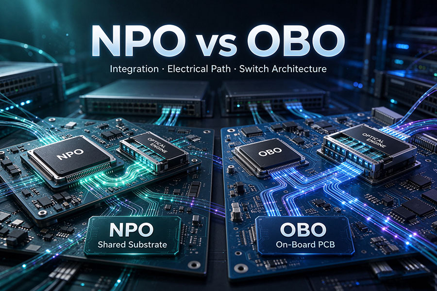
Two approaches in this transition are On-Board Optics (OBO) and Near-Packaged Optics (NPO). OBO mounts optical engines directly on the system printed circuit board (PCB), typically near the switch ASIC. NPO takes integration further by placing the ASIC package and optical engines on a shared high-performance substrate or interposer, depending on the implementation.
Both approaches aim to reduce the electrical distance between electronic and optical components. Their main difference is how the ASIC and optical engine are physically connected, which affects signal integrity, power consumption, packaging complexity, thermal management, and maintenance.
1. What Is On-Board Optics (OBO)?
On-Board Optics is an optical integration architecture in which optical engines are mounted directly on the system PCB rather than installed in front-panel transceiver cages.
The switch ASIC remains in its own semiconductor package, while the optical engines are positioned nearby on the same circuit board. High-speed electrical signals travel from the ASIC package through PCB traces to the optical engines, where they are converted into optical signals for transmission over fiber.
A typical OBO implementation includes:
Switch ASIC: Processes network packets and provides high-speed electrical interfaces.
ASIC package: Connects the switching silicon to the system PCB.
PCB electrical routing: Carries high-speed signals between the ASIC package and optical engines.
Electrical engine (EIC): Provides the electronic functions required to drive or receive high-speed signals.
Photonic integrated circuit (PIC): Performs optical modulation, detection, and other photonic functions.
Fiber interface: Connects the optical engine to external fiber-optic infrastructure.
Conceptual architecture: the ASIC and optical engine are separate components mounted on the same system PCB.
OBO shortens the electrical connection compared with front-panel pluggable optics because the optical engine can be positioned close to the ASIC. However, the high-speed electrical channel still travels through the PCB.
This arrangement offers an intermediate integration approach: it reduces the distance between electronic and optical components without requiring the optical engine to share a dedicated high-performance substrate with the ASIC package.
2. What Is Near-Packaged Optics (NPO)?
Near-Packaged Optics places optical engines closer to the switch ASIC through a more integrated packaging arrangement. Rather than mounting the optical engine independently on the main system PCB, NPO commonly uses a high-performance substrate or interposer to support the ASIC package and nearby optical engines.
The purpose is to create a shorter and more controlled electrical connection between the switching silicon and optical conversion components.
A representative NPO architecture includes:
Switch ASIC package: Contains the main switching silicon and its package-level electrical connections.
High-performance substrate or interposer: Provides the electrical routing between the ASIC package and optical engines.
Optical engine: Combines the relevant electronic and photonic components for optical signal conversion.
Fiber attachment: Provides the optical path between the engine and external fiber infrastructure.
System PCB: Supports the overall assembly and connects it to the remaining switch electronics.
Conceptual NPO arrangement. High-speed ASIC-to-optical-engine connections are routed through the shared high-performance substrate rather than relying on long main-PCB traces.
In this architecture, the optical engine can remain a separate component from the ASIC package. Some NPO implementations use socketed or separately assembled optical engines, allowing the electronic and optical components to be tested independently before final integration.
The exact definition of NPO can vary among industry proposals and vendors. Some designs emphasize a shared substrate, while others use different interposer or near-package assembly arrangements. The actual package structure and serviceability should therefore be confirmed against the specific platform design.
3. NPO vs On-Board Optics: Key Technical Differences
The main distinction between NPO and OBO is the substrate used to connect the optical engine to the switch ASIC. OBO relies on the main system PCB, while NPO uses a closer high-performance substrate or interposer arrangement.
| Technical Dimension | On-Board Optics (OBO) | Near-Packaged Optics (NPO) |
|---|---|---|
| Optical engine location | Mounted on the system PCB near the ASIC | Positioned near the ASIC on a shared high-performance substrate or interposer |
| ASIC connection | Through PCB traces | Through a shorter substrate-level electrical connection |
| Electrical path | ASIC package to PCB to optical engine | ASIC package to shared substrate to optical engine |
| PCB high-speed routing | Used for the ASIC-to-optical-engine connection | Can be avoided for the primary high-speed ASIC-to-engine connection |
| Electrical channel | Shorter than traditional front-panel pluggables | Typically shorter and more tightly controlled than OBO |
| Signal integrity | Depends on PCB material, routing, transitions, and channel loss | Benefits from substrate-level electrical routing and shorter channel length |
| Power efficiency | Potential improvement over front-panel optics | Potential further improvement through reduced electrical channel loss |
| Integration density | Limited by PCB placement and routing constraints | Can provide closer and denser optical-engine integration |
| Thermal design | Optical engines distributed across the system PCB | Optical engines located closer to the high-power ASIC package |
| Manufacturing | Requires board-level optical-engine assembly and testing | Requires tighter coordination of ASIC packaging, substrate, and optical-engine assembly |
| Maintenance | Depends on the mounting and fiber-interface design | Depends on whether the optical engine is socketed, removable, or permanently assembled |
| Integration complexity | Board-level integration | More demanding substrate-level integration |
Neither architecture has a universal advantage in every system. NPO can provide a shorter electrical path, but its benefits depend on substrate design, optical-engine implementation, thermal management, and manufacturing capability.
4. Electrical Signal Path and Signal Integrity
Electrical channel quality is a major reason for moving optical engines closer to the switch ASIC. As SerDes lane rates increase, PCB traces become more challenging because electrical signals experience insertion loss, reflections, crosstalk, and frequency-dependent attenuation.
In an OBO design, the signal travels from the ASIC package through the system PCB to the optical engine. Even when the optical engine is placed close to the ASIC, PCB routing remains part of the high-speed electrical channel.
In an NPO design, the high-speed connection can be routed through a shared high-performance substrate or interposer. This reduces reliance on the main PCB for the ASIC-to-optical-engine connection and allows tighter control of the electrical path.
| Signal Integrity Factor | OBO | NPO |
|---|---|---|
| Routing medium | Main system PCB | High-performance substrate or interposer |
| Electrical distance | Shortened compared with front-panel optics | Generally further reduced through substrate-level integration |
| Insertion loss | Depends on PCB channel length and material properties | Can benefit from a shorter, more controlled electrical channel |
| Impedance control | PCB traces, vias, and component transitions | Substrate routing and package-level transitions |
| Design focus | Board routing and optical-engine placement | Substrate design, package interfaces, and optical-engine placement |
A shorter channel can reduce the equalization and signal-conditioning burden, but it does not eliminate electrical design challenges. Substrate materials, impedance discontinuities, package transitions, crosstalk, and manufacturing tolerances remain important.
5. Power Consumption and Thermal Management
Reducing electrical channel length can improve energy efficiency because high-speed electrical signals require less compensation when the channel is shorter and better controlled. This is particularly important in high-capacity switches, where many optical interfaces operate simultaneously.
OBO can reduce the electrical distance compared with conventional front-panel optics. NPO can further reduce the channel length by using a more integrated substrate arrangement.
However, total system power depends on more than the electrical connection. Optical drivers, receivers, laser sources, switching ASICs, retimers where used, and cooling systems all contribute to the overall power budget.
Thermal management also becomes more demanding as optical engines move closer to the ASIC. The ASIC may generate substantial heat, and nearby photonic components can have their own temperature sensitivity and operating limits.
Key design considerations include:
Heat transfer between the switching ASIC and optical engines.
Thermal isolation or temperature control for sensitive optical components.
Airflow or liquid-cooling arrangements around densely integrated assemblies.
Thermal expansion across the PCB, substrate, and package materials.
Long-term reliability under repeated operating-temperature changes.
NPO may reduce electrical interconnect power, but the resulting system must still meet the cooling and reliability requirements of the complete switch platform.
6. Manufacturing, Reliability, and Maintenance
OBO and NPO also create different manufacturing and service requirements. OBO uses board-mounted optical engines, which means the optical components must be assembled and tested as part of the system PCB process.
NPO introduces a more specialized substrate and packaging arrangement. The ASIC package and optical engines must be electrically and mechanically compatible with the shared substrate. Depending on the implementation, separate testing before final assembly can help identify component-level defects.
| Operational Factor | OBO | NPO |
|---|---|---|
| Assembly | Optical engines mounted on the system PCB | Optical engines integrated through a high-performance substrate |
| Testing | Board-level and optical-engine validation | Separate component testing may be possible before final substrate assembly |
| Mechanical complexity | PCB mounting and fiber attachment | Substrate, package, optical-engine, and fiber-interface coordination |
| Repair | Depends on board-level mounting and rework capability | Depends on socketing and optical-engine replacement design |
| Failure isolation | Requires diagnosis of board-mounted components and electrical paths | Requires diagnosis across the ASIC, substrate, and optical-engine assembly |
| Upgrade flexibility | Limited by board design and component compatibility | Depends on the platform's modularity and substrate architecture |
It is important not to assume that every NPO optical engine is field-replaceable or that every OBO design requires complete board replacement. Both depend on the actual mechanical interface, assembly process, and maintenance strategy.
7. OBO vs NPO vs Pluggable Optics vs CPO
OBO and NPO are part of a broader progression toward closer integration of optical and electronic components. Comparing all four architectures makes their relative positions clearer.
| Architecture | Optical Engine Position | Electrical Connection | Integration Level |
|---|---|---|---|
| Pluggable Optics | Front-panel transceiver cage | ASIC package through PCB to front-panel module | Lowest integration |
| OBO | On the system PCB near the ASIC | ASIC package through PCB traces to optical engine | Board-level integration |
| NPO | Near the ASIC on a shared high-performance substrate or interposer | Short substrate-level electrical connection | Near-package integration |
| CPO | Integrated within the ASIC's common package architecture | Short package-level electrical connection | Co-packaged integration |
Pluggable optics prioritize module replacement and flexibility. OBO moves optical conversion onto the board. NPO brings the optical engine closer through a shared substrate. CPO integrates the optical engine and switching ASIC within a common package architecture.
These approaches should not be treated as mandatory stages in a single migration path. Different switch platforms may adopt different architectures according to bandwidth requirements, manufacturing capabilities, thermal constraints, and operational priorities.
8. Applications in 800G and 1.6T Data Center Networks
The demand for higher switching capacity in AI data centers is increasing pressure on the electrical interfaces between switch ASICs and optical engines. As 800G and 1.6T networking platforms develop, the available PCB routing space, electrical channel loss, module power, and front-panel density become important system-level constraints.
OBO and NPO offer different ways to address these challenges.
800G switching platforms: OBO and NPO architectures can be evaluated where conventional front-panel electrical channels become difficult to support at the required density and power envelope.
1.6T switching platforms: Higher electrical lane rates increase the importance of substrate design, short electrical paths, and optical-engine integration.
AI scale-out networks: High-bandwidth optical connectivity between GPU racks and network switches makes port density and system power important design factors.
Hyperscale data centers: Large switch deployments can benefit from improvements in aggregate interconnect power and physical integration.
It is important to distinguish optical data rate from packaging architecture. An 800G or 1.6T interface defines the nominal transmission capacity, while OBO and NPO define how the optical engine is physically integrated with the switching system.
Actual system performance depends on the switch ASIC, electrical interface, optical engine, network topology, fiber infrastructure, and workload traffic pattern.
9. How to Select Between OBO and NPO
The decision should be based on the complete switch platform rather than the optical engine's physical position alone.
OBO may be appropriate when:
The platform requires board-level optical integration without a shared high-performance ASIC substrate.
The PCB electrical channel can support the required lane rate and signal-integrity limits.
The manufacturer has an established board-level assembly and testing process.
The optical-engine placement and fiber routing fit the system's mechanical design.
The overall power and cooling requirements can be met with the selected architecture.
NPO may be appropriate when:
Reducing the ASIC-to-optical-engine electrical path is a major design objective.
The platform supports a suitable high-performance substrate or interposer.
Higher optical density is required around the switching ASIC.
The manufacturer can support the associated packaging and thermal requirements.
The optical-engine replacement and maintenance strategy is clearly defined.
Before selecting either architecture, engineers should evaluate electrical channel loss, SerDes compatibility, optical performance, fiber attachment, thermal limits, component reliability, manufacturing yield, and long-term maintenance costs.
10. Conclusion
NPO and On-Board Optics are two approaches to moving optical engines closer to high-performance switch ASICs. OBO mounts the optical engine on the main system PCB, reducing the distance compared with front-panel pluggable optics while retaining PCB-based high-speed electrical routing.
NPO uses a more integrated substrate or interposer arrangement to connect the ASIC package and optical engine. This can further shorten the electrical path and improve signal integrity and interconnect power efficiency, but it introduces additional packaging, thermal, and manufacturing considerations.
For 800G and 1.6T data center switches, both architectures are relevant to the evolution of high-density optical connectivity. The best choice depends on electrical channel requirements, optical-engine design, system power, thermal performance, manufacturing capability, and maintenance strategy.
For conventional high-speed optical connectivity, including 400G, 800G, and 1.6T transceiver solutions, visit the C-LIGHT optical transceiver portfolio. For product compatibility and network connectivity requirements, Contact C-LIGHT.
 >

 >
 >
 >
 >
 >
 >
 >