TEL:+86 132 6656 7067





As optical networking moves toward 400G, 800G, and 1.6T interfaces, reducing transceiver power consumption and signal-processing latency has become an important design objective. Linear Pluggable Optics (LPO) is one architecture addressing this challenge by removing conventional DSP-based retiming from the module's high-speed signal path and relying more heavily on the host ASIC's SerDes capabilities.
The term linear transmitter is closely related to this architecture, but it describes a narrower part of the optical communication system. A linear transmitter focuses on how the electrical signal drives the optical transmission components. LPO describes a broader pluggable module architecture that considers both transmit and receive paths.
Understanding this difference is important when evaluating optical transceivers, because a module with a linear transmitter is not automatically a complete LPO solution. The receiver architecture, retiming functions, host electrical interface, and end-to-end signal behavior must also be considered.
1. What Is Linear Pluggable Optics (LPO)?
Linear Pluggable Optics is a high-speed optical transceiver architecture that removes the conventional DSP or retimer from the module's high-speed data path. Instead of performing extensive digital signal processing inside the transceiver, LPO relies on the host switch ASIC or NIC SerDes to provide much of the required signal equalization and conditioning.
In a conventional retimed optical module, the incoming electrical signal passes through a DSP that performs functions such as equalization, clock recovery, and signal regeneration. The receive path also uses digital processing to recover the incoming signal before returning it to the host.
LPO changes this division of responsibility. Its high-speed signal path uses linear analog components, including a linear transmitter driver and a linear transimpedance amplifier (TIA), while the host system handles more of the signal conditioning.
A typical LPO module contains:
Optical source: A laser or other suitable optical source for generating the transmitted light.
Modulator: Converts the electrical drive signal into optical modulation where the selected transmitter architecture requires a separate modulator.
Linear driver: Amplifies and drives the electrical signal toward the optical transmitter while preserving its waveform characteristics.
Photodetector: Converts incoming optical signals into electrical signals.
Linear TIA: Amplifies the photodetector current while preserving the received signal characteristics for the host receiver.
Management circuitry: Supports module monitoring, identification, control, and other required management functions.
The defining feature is not the absence of all electronics. LPO still contains active analog components and management circuitry. Its distinction is the absence of conventional DSP-based retiming in the module's high-speed data path.
2. What Is a Linear Transmitter?
A linear transmitter is a transmit-side architecture in which the electrical signal is amplified and delivered to the optical source or modulator while preserving its amplitude information and waveform characteristics. The objective is to avoid unnecessary digital regeneration within the transmitter path.
In a high-speed PAM4 optical interface, the electrical signal carries multiple amplitude levels. A linear driver must maintain sufficient signal fidelity so that the optical transmitter can reproduce the intended modulation accurately.
A simplified linear transmitter path includes:
Host SerDes: Generates the high-speed electrical data signal.
Electrical interface: Carries the signal from the host to the optical module.
Linear driver: Provides the required electrical drive while maintaining waveform characteristics.
Optical transmitter: Converts the electrical signal into a modulated optical signal.
Depending on the implementation, the optical transmitter may use a directly modulated laser or an externally modulated laser arrangement. The specific driver, laser, and modulator design depends on the transmission rate, optical interface, and module architecture.
Importantly, the term linear transmitter alone does not specify what happens in the receiver path. It does not establish whether the module contains a DSP, whether the receiver is linear or retimed, or where clock recovery and equalization are performed across the complete link.
3. LPO vs Linear Transmitter: Key Differences
The main difference is architectural scope. A linear transmitter describes the transmit-side signal path, while LPO defines a broader pluggable optical solution in which both transmission and reception are designed around a linear, non-retimed high-speed signal path.
| Technical Dimension | LPO | Linear Transmitter |
|---|---|---|
| Definition | Complete linear pluggable optical module architecture | Transmit-side signal architecture or component arrangement |
| Scope | Transmit and receive signal paths | Optical transmission path |
| DSP architecture | No conventional module DSP retimer in the high-speed data path | Does not independently define the module's complete DSP architecture |
| Transmit components | Linear driver and optical transmitter | Linear driver and optical transmitter |
| Receive architecture | Uses a linear receive path, typically with a linear TIA | Not defined by the transmitter term |
| Signal processing | Relies heavily on host SerDes capabilities for signal conditioning | Describes the transmit-side handling of the signal |
| Module power | Can reduce power by removing module DSP-based retiming | Power savings depend on the complete module design |
| Latency | Removes module DSP retiming latency from the high-speed path | Cannot establish complete link latency by itself |
| Interoperability | Requires compatibility across host, module, electrical channel, and optical link | Requires suitable electrical and optical interface compatibility |
| System classification | A complete pluggable optics architecture | A transmitter implementation characteristic |
4. Signal Path: Conventional DSP Transceiver vs LPO
The difference becomes clearer when the electrical and optical signal paths are examined. A conventional DSP-based transceiver processes and retimes the signal within the module. An LPO architecture removes that module-level DSP stage and relies on the host's high-speed SerDes and associated signal-conditioning capabilities.
Conventional DSP-based optical module:
The module DSP performs digital signal processing and retiming before the optical transmission stage.
LPO optical module:
The module does not contain a conventional DSP retiming stage in its high-speed transmit path.
On the receive side, the conventional module typically uses a DSP-based processing stage after the photodetector and TIA. In an LPO implementation, a linear TIA delivers the received electrical waveform toward the host SerDes, which performs much of the required equalization and signal recovery.
The actual signal-processing partition depends on the implementation and applicable interface specification. It is therefore important to distinguish the simplified block diagrams from the complete electrical and optical link budget.
5. Power Consumption and Latency
One of the main reasons for developing LPO is the increasing power demand of high-speed optical connectivity. As switch port speeds move from 400G to 800G and beyond, the number of optical modules in a data center can create substantial aggregate power consumption.
In conventional retimed modules, the DSP can account for a significant portion of module power. Removing this component can reduce electrical power consumption and thermal dissipation.
| Performance Factor | DSP-Based Transceiver | LPO |
|---|---|---|
| Module DSP | Present in the conventional retimed architecture | Removed from the high-speed data path |
| Power consumption | Higher due to module-level digital processing | Potentially lower due to simplified signal processing |
| Thermal dissipation | Includes heat generated by the DSP | Reduced module heat contribution is possible |
| Processing latency | Includes module DSP processing and retiming delay | Eliminates module DSP retiming delay |
| Signal compensation | More processing is performed within the module | Greater dependence on host SerDes and linear analog components |
| Host requirements | More flexibility from module-level signal conditioning | Requires strong host equalization and signal integrity |
A linear transmitter by itself does not guarantee the same system-level power or latency benefits as LPO. A module may use a linear transmit stage while retaining other digital processing functions elsewhere in its signal path.
Actual power savings depend on the data rate, optical technology, driver and TIA design, management circuitry, host implementation, and operating conditions. Similarly, removing module DSP processing reduces one source of latency but does not eliminate propagation delay, host processing, or other system delays.
6. Signal Integrity and Host Compatibility
Removing the DSP from the module changes where signal conditioning takes place. In a conventional retimed design, the module provides additional opportunities to compensate for electrical channel degradation. In LPO, the host ASIC's transmit and receive capabilities become more important because the electrical and optical channel must operate successfully without conventional module-level retiming.
Several factors influence LPO link performance:
Host SerDes capability: Transmit equalization and receive equalization must support the intended electrical and optical channel.
PCB channel loss: Connector transitions, PCB traces, vias, and other electrical discontinuities affect signal integrity.
Driver linearity: The transmitter driver must preserve the signal's required amplitude characteristics.
TIA performance: The receive-side analog front end must provide adequate bandwidth, noise performance, and linearity.
Optical link budget: Transmitter output, receiver sensitivity, fiber attenuation, and other optical impairments must remain within the supported limits.
Host-module interoperability: The host SerDes and optical module must be validated as a complete electrical and optical link.
These requirements can make LPO deployment more dependent on the exact switch ASIC, NIC, module design, and firmware configuration. A module that works in one platform should not automatically be assumed to deliver the same performance in another.
7. Can a Linear Transmitter Be Used in a DSP-Based Optical Module?
Yes. The terms linear transmitter and LPO should not be treated as mutually exclusive module categories. A transceiver can use a linear transmitter stage while retaining DSP processing elsewhere in the module.
For example, an optical module could use a linear driver on the transmit side but retain a DSP or retiming function on the receive side. Another design could use digital processing on the transmit path while using a linear receiver. These architectures distribute signal processing differently and should not automatically be classified as fully linear LPO.
This is why evaluating only the transmitter driver is insufficient. Engineers need to examine both directions of the signal path and identify whether digital retiming remains inside the module.
Related architectures include:
Fully retimed optics: Uses module-level digital signal processing and retiming in the applicable transmit and receive paths.
LPO: Uses linear transmit and receive paths without conventional module DSP retiming in the high-speed data path.
LRO: Linear Receive Optics, an intermediate architecture that retains a retimed transmit path while using a linear receive path.
These distinctions are particularly relevant when evaluating high-speed optical modules for AI clusters, GPU networks, and data center switching systems.
8. Applications in 400G, 800G, and 1.6T Optical Networks
Higher-speed interfaces increase the importance of power efficiency, signal integrity, and thermal management. LPO is particularly relevant to short-reach data center connectivity where host SerDes capabilities and controlled electrical channels can support a linear optical architecture.
| Optical Network Generation | Typical Electrical Signaling | Architecture Considerations |
|---|---|---|
| 400G | Commonly 4 × 100G-class PAM4 lanes | Linear driver and receiver design, host compatibility, and optical reach |
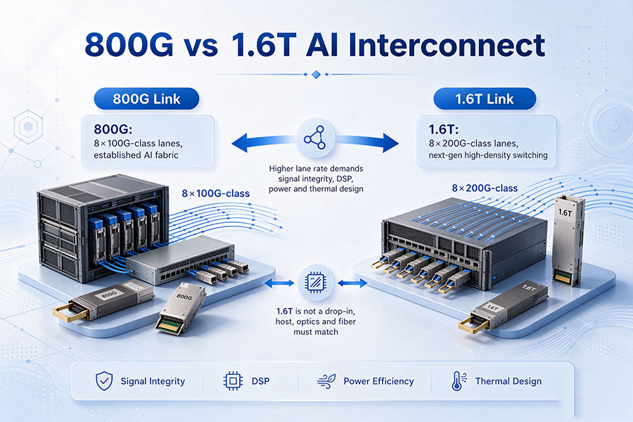
| 800G | Commonly 8 × 100G-class PAM4 lanes | Higher aggregate bandwidth, module power, thermal density, and multi-lane signal integrity |
| 1.6T | Commonly 8 × 200G-class PAM4 lanes in relevant architectures | 224G-class electrical interfaces, tighter signal-integrity requirements, and evolving linear optics specifications |
These are representative lane architectures rather than universal definitions for every optical module. The actual interface must be verified against its applicable Ethernet standard, optical specification, electrical host interface, and module implementation.
Potential deployment areas include:
GPU-to-GPU and GPU-server connectivity in AI infrastructure.
Short-reach server-to-switch links in high-density data centers.
Leaf-to-spine connections where the host and optical module support the required linear interface.
High-speed Ethernet fabrics in hyperscale computing environments.
Selected InfiniBand and other high-performance networking platforms with validated LPO support.
For these applications, the optical interface must be selected according to transmission distance, wavelength, fiber type, connector, host platform, and link budget. Relevant product options can be found in the C-LIGHT optical transceiver portfolio.
9. How to Evaluate LPO and Linear Transmitter Solutions
When evaluating an optical module described as linear, the first step is to establish whether the term refers only to the transmitter or to the complete module architecture.
A practical technical evaluation should include:
Identify the signal-processing architecture: Confirm whether the module contains a DSP, CDR, or other retiming function in either high-speed direction.
Review the transmit path: Check the driver architecture, output characteristics, optical source, and modulation method.
Review the receive path: Confirm whether the module uses a linear TIA, a limiting receiver, or a DSP-based receive architecture.
Verify host compatibility: Confirm that the switch ASIC or NIC supports the required SerDes configuration and equalization capabilities.
Check electrical and optical specifications: Validate lane rate, signaling format, optical reach, transmitter power, receiver sensitivity, and link budget.
Perform interoperability testing: Validate the complete host-to-module-to-fiber-to-module-to-host link under the intended operating conditions.
For high-speed LPO applications, testing should also consider bit error rate, electrical eye characteristics, optical performance, thermal behavior, and operation across supported host configurations.
10. Conclusion
LPO and linear transmitter are related terms, but they describe different levels of optical communication architecture. A linear transmitter refers to the transmit-side electrical-to-optical signal path, whereas LPO defines a complete pluggable module architecture that uses linear transmit and receive paths without conventional module DSP retiming in the high-speed data path.
A linear transmitter may be used in an LPO module, but it does not independently establish that the complete transceiver is an LPO solution. The receiver architecture, DSP placement, host SerDes capabilities, and end-to-end link performance must also be considered.
As 400G, 800G, and 1.6T optical networks evolve, the distinction becomes increasingly important for power optimization, thermal management, signal integrity, and platform interoperability. Selecting the right optical architecture requires evaluating the complete electrical and optical link rather than relying on a single component description.
For optical transceiver requirements, high-speed connectivity, and platform compatibility support, Contact C-LIGHT.
 >

 >
 >
 >
 >
 >
 >
 >