TEL:+86 132 6656 7067





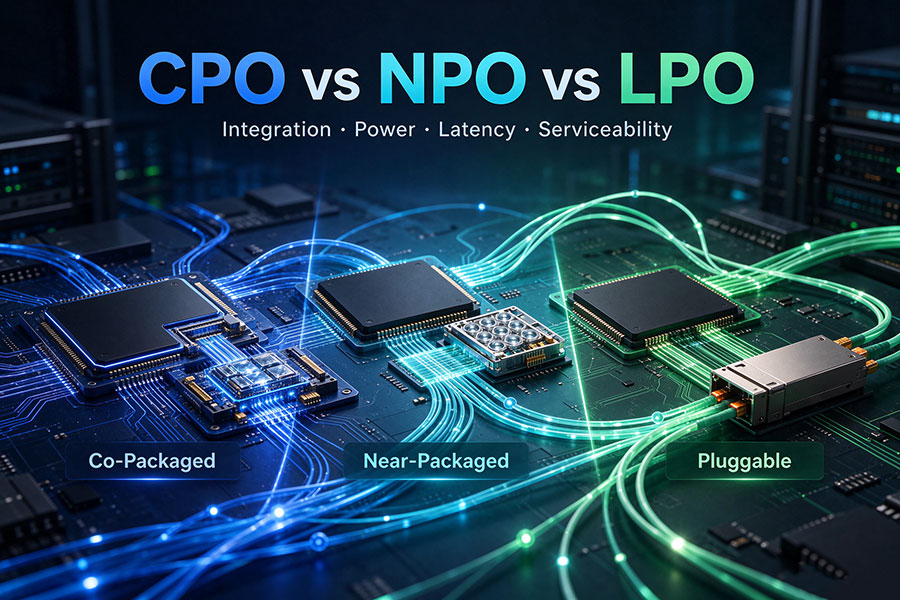
As AI data center switches move toward higher aggregate bandwidth, the electrical connection between switching silicon and optical interfaces is becoming a major system-design constraint. Co-Packaged Optics (CPO), Near-Packaged Optics (NPO), and Linear Pluggable Optics (LPO) address this challenge through different integration strategies. Their differences affect signal integrity, power distribution, thermal management, optical density, field maintenance, and the way network equipment is designed.
1. What CPO, NPO, and LPO Mean
CPO, NPO, and LPO are often discussed together because each aims to improve the efficiency of high-speed optical connectivity. However, they do not describe exactly the same engineering dimension. CPO and NPO primarily describe where optical engines are positioned relative to the host ASIC, while LPO describes a pluggable optical architecture that changes how electrical signal processing is divided between the host and the module.
The distinction matters when evaluating vendor roadmaps. A system with optical engines close to a switch ASIC is not automatically CPO. Likewise, removing a conventional DSP from a front-panel module does not make it NPO. Architecture classification depends on physical placement, packaging boundaries, and signal-processing implementation.
2. CPO: Optical Engines Integrated with the ASIC Package
Co-Packaged Optics integrates optical engines with the host ASIC within a common package structure. Instead of routing high-speed electrical signals across a substantial section of the switch PCB to reach front-panel transceivers, the electrical connection between the ASIC and optical engine is kept within the package-level assembly.
This approach targets one of the major limitations of high-bandwidth switch platforms: the increasing electrical cost of moving signals between the switching chip and optical interfaces. Shorter electrical paths can reduce channel loss and the amount of electrical compensation required, creating opportunities for higher bandwidth density and improved energy efficiency.
Potential advantages of CPO
Short electrical interconnects: Optical conversion takes place close to the switching silicon, reducing the distance traveled by high-speed electrical signals.
High bandwidth density: Optical interfaces can be integrated around the ASIC package rather than being limited entirely by conventional front-panel module layouts.
Power optimization opportunities: A shorter electrical channel can reduce some signal-conditioning requirements, although total system power depends on the complete implementation.
Support for future switch bandwidth: CPO is particularly relevant to designs targeting very high aggregate switch capacity and dense AI network fabrics.
Engineering and operational challenges
CPO creates a tighter relationship between the ASIC, optical engines, package substrate, fiber attachment, and cooling system. Optical coupling accuracy, packaging yield, thermal interaction, laser architecture, and long-term reliability all become important design considerations.
Maintenance is another major consideration. A conventional front-panel transceiver can usually be replaced independently. An optical engine integrated into a package is not normally serviced in the same way. Some designs may use external or replaceable laser sources, but this does not make the complete optical engine equivalent to a hot-swappable front-panel module.
3. NPO: Moving Optical Engines Closer Without Full Co-Packaging
Near-Packaged Optics places optical engines close to the host ASIC while retaining a separate optical component and packaging boundary. The optical engine may be mounted on the host board or incorporated into a closely integrated board-level assembly, depending on the implementation.
NPO addresses the electrical-distance problem without requiring the same degree of package-level integration as CPO. The connection between the ASIC and optical engine is shorter than in a conventional front-panel architecture, but the optical subsystem remains distinct from the ASIC package.
Why NPO is attracting attention
Reduced electrical reach: Shorter PCB traces between the ASIC and optical engine can ease high-speed channel design.
Greater integration flexibility: The optical subsystem remains separate from the ASIC package, allowing different mechanical and assembly approaches.
Potential power savings: Reduced electrical-channel loss and simplified signal-conditioning requirements may improve system efficiency.
Intermediate integration level: NPO provides a design path between front-panel pluggables and fully co-packaged optical engines.
NPO still requires careful coordination between board layout, power delivery, optical fiber routing, thermal management, and service access. Its maintainability depends on whether the optical engine is socketed, replaceable, or permanently integrated into the board assembly. The NPO label alone does not guarantee field replacement.
Terminology can also vary among vendors and industry groups. When evaluating an NPO platform, engineers should examine the actual package boundary, optical-engine mounting method, electrical interface, and maintenance procedure rather than relying on the architecture name alone.
4. LPO: Linear Signal Processing in a Pluggable Module
Linear Pluggable Optics retains the familiar front-panel optical module form factor but changes the signal-processing architecture. A conventional DSP-based optical module performs substantial signal conditioning and retiming internally. LPO removes the conventional module DSP retiming function from the high-speed data path and uses linear electrical components, placing greater responsibility on the host ASIC SerDes and the overall electrical channel.
The optical module remains physically removable. This is a significant operational difference from many CPO and NPO implementations. Network operators can retain a front-panel module replacement model while pursuing lower module power and latency.
Potential advantages of LPO
Lower module power: Removing or simplifying DSP-based retiming can reduce power consumption within the optical module.
Reduced processing latency: A simpler signal path can avoid some module-side digital processing delay.
Familiar service model: LPO maintains a pluggable module architecture, supporting individual module replacement.
Less disruptive mechanical integration: The host platform can retain a front-panel optical interface, provided it is designed and qualified for the LPO implementation.
Why host compatibility becomes more demanding
LPO depends heavily on the electrical performance of the host SerDes, PCB traces, connectors, module driver, and receiver path. A module that works in one switch platform may not deliver the same performance in another platform if their electrical channel characteristics differ.
System-level validation is therefore essential. Engineers need to assess insertion loss, return loss, crosstalk, equalization capability, signal margin, FEC behavior, and interoperability across the complete host-to-module link. Lower module power does not automatically mean that every LPO implementation will consume less power at the system level.
LPO should also be distinguished from Linear Receive Optics (LRO). LRO commonly describes a half-retimed arrangement in which the transmit path remains retimed while the receive path uses linear processing. The exact implementation should be confirmed from the module and platform specifications.
5. CPO vs NPO vs LPO: Main Technical Differences
| Technical Factor | CPO | NPO | LPO |
|---|---|---|---|
| Full Name | Co-Packaged Optics | Near-Packaged Optics | Linear Pluggable Optics |
| Optical Engine Location | Within the ASIC package structure | Near the ASIC, but separately packaged | Front-panel pluggable module |
| Integration Level | Highest of the three | High, with a separate optical subsystem | Conventional pluggable mechanical architecture |
| Electrical Path | Very short, package-level connection | Short board-level connection | Host PCB channel to front-panel module |
| Module DSP | Architecture-dependent; package-level signal design | Architecture-dependent | Conventional module DSP retiming is removed from the high-speed path |
| Power Optimization | High potential through package-level integration | Potential reduction through shorter electrical paths | Potential reduction through simplified module signal processing |
| Latency | Can reduce electrical and signal-conditioning overhead | Can reduce electrical-channel overhead | Can reduce module DSP-related latency |
| Cooling | Closely coupled to ASIC and package thermal design | Board-level and ASIC-adjacent thermal planning | Module and host airflow or liquid-cooling design |
| Field Replacement | Generally more complex than module replacement | Depends on mounting and service design | Individual pluggable modules can be replaced |
| Host Dependency | Strong package and platform co-design | Strong board-level integration and qualification | Strong host SerDes and electrical-channel dependency |
| Typical Design Priority | Bandwidth density and electrical-path minimization | Shorter electrical reach with separate optical packaging | Lower module power while retaining pluggability |
The table describes general architectural tendencies rather than fixed performance guarantees. Power, latency, cooling requirements, and serviceability vary with ASIC generation, optical-engine design, signal-processing partitioning, and system implementation.
6. Electrical Reach, Signal Integrity, and Power Consumption
The electrical channel between the host ASIC and optical conversion point is one of the most important differences among these architectures. As signaling rates increase, PCB insertion loss, connector discontinuities, crosstalk, and equalization requirements become more difficult to manage.
CPO places optical conversion closest to the ASIC, keeping the high-speed electrical connection within the package-level assembly. NPO also shortens the channel, but retains a separate optical engine. LPO keeps the module at the front panel and relies on a carefully controlled linear channel between the host SerDes and module electronics.
This creates three different approaches to the same system problem:
CPO: Reduce the electrical distance through package-level optical integration.
NPO: Reduce the electrical distance through close board-level placement.
LPO: Simplify module-side signal processing while preserving a front-panel optical interface.
Power comparisons must account for more than the optical module itself. A complete evaluation should include ASIC SerDes power, module or optical-engine power, retiming and DSP functions, laser power, cooling infrastructure, power conversion losses, and any additional system components. A lower-power optical engine does not necessarily translate into the same percentage reduction in total switch power.
7. Thermal Design and Cooling Requirements
Higher optical bandwidth increases the importance of thermal design, but each architecture creates a different thermal boundary.
In CPO systems, optical engines are located close to a high-power ASIC. Their thermal environment is therefore closely linked to package design, cold-plate configuration, heat spreading, and the thermal behavior of neighboring components. The cooling solution must account for both the switching silicon and the optical components.
NPO moves optical engines away from the ASIC package but keeps them on the same board or in a nearby assembly. This provides more separation than CPO, although local airflow, component spacing, and heat transfer from the ASIC remain important.
LPO retains front-panel modules, allowing thermal management through module heatsinks, airflow design, and host chassis cooling. However, removing a DSP does not eliminate thermal constraints. Linear drivers, TIAs, optical devices, and high-speed host electronics still generate heat.
8. Reliability, Maintenance, and Deployment Considerations
Optical integration changes not only the signal path but also the way equipment is assembled, tested, repaired, and upgraded. For operators managing large AI clusters, serviceability can be as important as power efficiency.
| Operational Area | CPO | NPO | LPO |
|---|---|---|---|
| Optical Component Access | Integrated into package-level assembly | Board-level access, implementation-dependent | Front-panel access |
| Replacement Strategy | May involve larger assembly or system-level service | Depends on socketing and mounting design | Individual module replacement |
| Fiber Management | Requires careful package and chassis routing | Requires board-level fiber routing and strain management | Uses established front-panel fiber management practices |
| Manufacturing Focus | Package integration, optical coupling, and assembly yield | Board integration, optical alignment, and mechanical access | Module manufacturing and host-platform qualification |
| Field Troubleshooting | May require system-level diagnostics | Depends on optical-engine accessibility | Module-level diagnostics and replacement are familiar |
Reliability should be evaluated at the system level rather than inferred from integration density. CPO may reduce some electrical interconnect risks while introducing demanding package, fiber-coupling, and thermal requirements. NPO reduces electrical reach but adds board-level optical integration. LPO retains replaceable modules but requires tight control of the host electrical channel and interoperability.
9. Applications in AI Data Centers and High-Speed Networks
AI training clusters create sustained east-west traffic among GPUs, accelerators, and high-performance network switches. As switch capacity increases, the electrical interface between the ASIC and optical links can become a limiting factor in power, density, and signal integrity.
CPO applications
CPO is relevant to highly integrated switch platforms where bandwidth density and shorter electrical connections are major priorities. It is particularly attractive for designs that can justify close coordination between ASIC packaging, optical engines, cooling systems, and network equipment manufacturing.
NPO applications
NPO may suit platforms seeking shorter electrical channels without placing the optical engine inside the ASIC package. It provides a separate optical subsystem, although the exact level of serviceability and mechanical flexibility depends on the implementation.
LPO applications
LPO can be considered for switch platforms with suitable host SerDes capability and carefully controlled electrical channels. It is attractive when lower module power and latency are priorities and operators want to retain front-panel optical module replacement.
These architectures can coexist within the broader data center ecosystem. A network may use different optical approaches at different layers or in different equipment generations rather than adopting one architecture across every link.
10. Where Pluggable Optical Transceivers Fit in This Evolution
CPO, NPO, and LPO do not eliminate the need to select optical connectivity according to data rate, reach, fiber type, wavelength, connector, and host-platform compatibility. Even as optical engines move closer to switching silicon, pluggable transceivers remain important in existing data centers and in network links where modular replacement and deployment flexibility are priorities.
C-LIGHT provides pluggable optical transceiver solutions for high-speed data center and network applications. Relevant product families include:
800G OSFP Optical Transceivers – including SR8, DR8, 2×FR4, and other configurations for AI data centers, cloud networks, and high-performance computing.
1.6T OSFP-RHS Optical Transceivers – designed for next-generation 1.6Tb/s connectivity and high-density network platforms.
400G QSFP-DD Optical Transceivers – covering short-reach data center links as well as extended-reach and DCI applications.
These products are conventional pluggable transceiver families; their product pages should not be interpreted as evidence that a particular model is an LPO, NPO, or CPO optical engine. The distinction is important because an optical module's data rate and form factor do not, by themselves, establish its signal-processing architecture or package integration method.
When selecting a pluggable solution, network engineers should verify the host switch model, supported form factor, electrical interface, optical standard, FEC configuration, power budget, thermal limits, fiber plant, and required transmission distance. For platforms moving toward LPO or more integrated optical architectures, host-specific validation becomes especially important.
11. How to Select the Right Architecture
The appropriate architecture depends on the system's performance targets and operational constraints. A useful selection process starts with the electrical channel and service model rather than assuming that the most integrated design is always the best choice.
Choose CPO when: Package-level integration, high bandwidth density, and reduced electrical reach justify the additional complexity in thermal design, optical coupling, manufacturing, and maintenance.
Evaluate NPO when: The design needs shorter ASIC-to-optics electrical connections but benefits from retaining a distinct optical subsystem outside the ASIC package.
Evaluate LPO when: The host SerDes and electrical channel can support linear operation, and lower module power and latency are priorities without abandoning front-panel pluggability.
Before committing to a platform, engineering teams should request architecture diagrams, electrical channel specifications, optical interface details, thermal data, FEC requirements, service procedures, and system-level test results. Interoperability should be validated using the actual switch hardware, firmware, module or optical engine, and fiber configuration.
12. Conclusion
CPO, NPO, and LPO address different parts of the optical interconnect challenge. CPO integrates optical engines within the ASIC package structure to minimize electrical reach. NPO places separate optical engines close to the ASIC, providing a less tightly integrated package boundary. LPO retains front-panel pluggability while simplifying module-side signal processing and relying more heavily on the host electrical channel.
The decision is not simply about which architecture offers the shortest electrical path or the lowest module power. Bandwidth density, total system energy, thermal design, manufacturing yield, optical coupling, serviceability, and platform interoperability all influence the final choice.
As AI data center networks move toward higher switch capacities, these architectures are likely to coexist. The most suitable solution will depend on the network layer, equipment design, deployment scale, and operational requirements.
For high-speed optical connectivity requirements, product compatibility, or customized transceiver solutions, Contact C-LIGHT.
 >

 >
 >
 >
 >
 >
 >
 >