TEL:+86 132 6656 7067




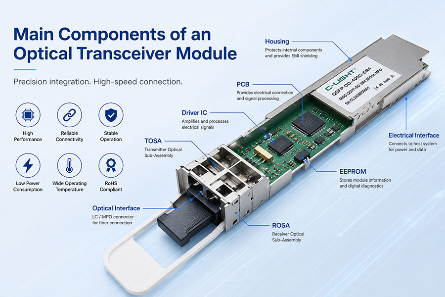
An optical transceiver module is a compact networking device that converts electrical signals into optical signals for transmission and converts received optical signals back into electrical signals. It is widely used in data centers, telecom networks, cloud computing, AI infrastructure, Ethernet, and storage networks.
Although optical transceivers are available in different speeds and form factors, most modules consist of several key components, including optical transmitters, receivers, laser drivers, TIAs, DSPs, optical interfaces, control circuits, and power management components.
1. What Is an Optical Transceiver Module?
An optical transceiver is a device that integrates both a transmitter and a receiver into one module. The transmitter converts electrical data into optical signals, while the receiver converts incoming optical signals back into electrical data.
Common optical transceiver form factors include SFP, SFP+, SFP28, QSFP28, QSFP56, QSFP-DD, OSFP, and other high-speed designs.
Depending on the application, optical transceivers can support data rates from 1G to 10G, 25G, 40G, 100G, 200G, 400G, 800G, and next-generation 1.6T transmission.
2. What Are the Main Components of an Optical Transceiver?
An optical transceiver consists of several optical, electrical, mechanical, and control components. The exact architecture depends on the transmission speed, optical reach, wavelength configuration, and form factor.
2.1 Optical Transmitter
The optical transmitter converts electrical signals into optical signals. The main optical source is usually a semiconductor laser.
Common laser technologies include VCSEL, DFB, EML, and other high-speed laser designs.
The selected laser depends on the application. For example, VCSEL technology is widely used in short-distance multimode applications, while DFB and EML technologies are commonly used for longer-distance single-mode transmission.
2.2 Optical Receiver
The optical receiver detects incoming optical signals and converts them into electrical signals.
Common optical detectors include PIN photodiodes and APD photodiodes. The receiver design depends on the required transmission distance, optical power, sensitivity, and data rate.
2.3 Laser Driver
The laser driver provides the electrical drive signal required by the laser. It controls the laser's modulation and helps maintain stable optical output.
In high-speed optical transceivers, the laser driver must support high-speed electrical signals while maintaining signal integrity and power efficiency.
2.4 TIA
TIA stands for Transimpedance Amplifier. It amplifies the small electrical current generated by the photodetector and converts it into a voltage signal that can be processed by the receiver circuitry.
The performance of the TIA directly affects receiver sensitivity, bandwidth, and overall signal quality.
2.5 DSP
DSP stands for Digital Signal Processor. DSPs are particularly important in advanced optical transceivers such as 400G, 800G, and 1.6T modules.
A DSP can perform functions such as equalization, signal recovery, modulation processing, forward error correction, and compensation for optical transmission impairments.
2.6 MUX and DEMUX
Multi-wavelength optical transceivers use optical multiplexer and demultiplexer components to combine and separate different wavelengths.
For example, a 100G LR4 module uses multiple optical wavelengths that are combined onto a single optical fiber through a MUX and separated at the receiving side through a DEMUX.
CWDM, LAN-WDM, LWDM, and DWDM optical technologies can use different wavelength arrangements and optical filtering architectures.
2.7 Optical Interface
The optical interface connects the internal optical components with the external fiber. It can include lenses, optical coupling structures, filters, isolators, and other optical components.
The optical interface is designed to ensure efficient optical coupling and stable signal transmission between the transceiver and fiber.
2.8 MCU and Control Circuit
The MCU, or microcontroller unit, manages module operation and communication with the host system.
It can monitor operating parameters such as temperature, supply voltage, transmitter optical power, receiver optical power, and laser bias current.
2.9 EEPROM and Module Memory
Optical transceivers include memory for storing module identification and configuration information.
Depending on the module, this information can include part number, serial number, supported data rate, wavelength, vendor information, and diagnostic parameters.
2.10 PCB and Power Management
The printed circuit board connects the electrical, optical, and control components inside the module.
Power-management circuits provide the required voltage levels and help control the module's overall power consumption and thermal performance.
3. How Does an Optical Transceiver Work?
The basic operating process can be divided into two directions: transmission and reception.
Transmit Path
Electrical Signal → DSP/Driver → Laser → Optical Signal → Fiber
The host device sends an electrical signal to the optical module. The driver controls the laser, which converts the electrical signal into an optical signal. The optical signal is then transmitted through the fiber.
Receive Path
Fiber → Photodiode → TIA → DSP/Receiver → Electrical Signal
The receiver detects the incoming optical signal. The photodiode converts it into an electrical current, the TIA amplifies the signal, and the receiver circuitry or DSP processes it before sending the recovered electrical data to the host device.
4. Optical Components vs. Electrical Components
| Component | Function | Category |
|---|---|---|
| Laser | Converts electrical data into optical signals | Optical |
| Photodiode | Converts optical signals into electrical signals | Optical |
| MUX/DEMUX | Combines or separates optical wavelengths | Optical |
| Laser Driver | Controls and drives the laser | Electrical |
| TIA | Amplifies the received electrical signal | Electrical |
| DSP | Processes and recovers high-speed signals | Electrical |
| MCU | Controls monitoring and management functions | Control |
| EEPROM | Stores module information and configuration data | Memory |
| PCB | Connects and supports electronic components | Electrical |
5. Components Used in Different Optical Modules
100G Optical Transceivers
100G optical modules may use technologies such as VCSEL, DFB, or EML depending on the transmission distance and optical architecture.
For example, C-LIGHT 100G modules include solutions such as 100G SR4, DR4, FR4, LR4, ER4, and ZR4 for different data center and telecom applications.
400G Optical Transceivers
400G optical modules typically have more complex optical and electrical architectures than lower-speed modules.
C-LIGHT provides 400G solutions including SR4, DR4, DR8, FR4, LR4, ZR, and ZR+ configurations for data center, AI, DCI, and telecom applications.
Depending on the product, a 400G module may integrate multiple lasers, photodetectors, optical MUX/DEMUX components, high-speed drivers, TIAs, and DSP technology.
800G Optical Transceivers
800G modules are designed for high-bandwidth AI and data center networks. They typically use advanced high-speed electrical and optical components to support multiple optical lanes.
C-LIGHT provides 800G solutions including 800G SR8, DR8, 2×FR4, and ZR+ optical transceivers, as well as 800G DAC and AOC solutions.
6. Optical Components in CWDM and DWDM Transceivers
Wavelength division multiplexing modules require additional optical components to transmit multiple wavelengths through the same fiber.
CWDM
CWDM uses relatively wide wavelength spacing and is commonly used for cost-effective multi-wavelength transmission over moderate distances.
C-LIGHT provides CWDM optical modules and passive CWDM MUX/DEMUX solutions for data center and telecom applications.
DWDM
DWDM uses much narrower wavelength spacing and supports a higher number of optical channels within the same fiber.
C-LIGHT DWDM solutions include high-speed coherent products such as 400G ZR and ZR+ optical transceivers for DCI, metro, and long-distance optical transmission.
7. Why Are DSPs Important in 400G and 800G Modules?
As optical transmission speeds increase, maintaining signal integrity becomes more challenging.
High-speed modules may experience electrical loss, optical impairments, dispersion, noise, and other signal-quality issues. Advanced DSP technology helps process and recover high-speed signals.
This is why DSP architecture is particularly important in modern 400G, 800G, and 1.6T optical transceivers.
8. How Do Optical Transceiver Components Affect Performance?
Transmission Distance
The laser type, optical power, receiver sensitivity, FEC, and optical design all influence the achievable transmission distance.
Bandwidth
High-speed drivers, TIAs, DSPs, lasers, and photodetectors must work together to support the required data rate.
Power Consumption
DSPs, drivers, lasers, and other electronic components contribute to the total power consumption of an optical transceiver.
Thermal Performance
Higher-speed optical modules generate more heat. Thermal management is therefore an important part of the module design.
Reliability
The quality and stability of optical and electronic components directly affect module reliability and long-term network operation.
9. C-LIGHT Optical Transceiver Solutions
C-LIGHT provides optical transceiver solutions covering multiple data rates, wavelengths, transmission distances, and network applications.
100G: SR4, DR4, FR4, LR4, ER4, ZR4 and other solutions.
200G: QSFP56 solutions for high-speed data center and network applications.
400G: SR4, DR4, DR8, FR4, LR4, ZR, and ZR+ optical transceivers.
800G: SR8, DR8, 2×FR4, ZR+, DAC, and AOC solutions.
1.6T: Next-generation optical and high-speed interconnect solutions for AI and hyperscale data centers.
These products are designed for applications including data centers, AI infrastructure, cloud computing, Ethernet, InfiniBand, telecom networks, DCI, and high-performance computing.
10. Conclusion
An optical transceiver is a highly integrated device that combines optical, electrical, control, and mechanical technologies.
The main components include the laser, photodiode, laser driver, TIA, DSP, MUX/DEMUX, optical interface, MCU, EEPROM, PCB, and power-management circuits.
As network speeds increase from 100G to 400G, 800G, and 1.6T, optical transceiver architectures become increasingly sophisticated. The selection and integration of these components directly affect bandwidth, transmission distance, power consumption, thermal performance, and reliability.
With a broad portfolio of high-speed optical transceivers, DAC, AOC, and coherent optical solutions, C-LIGHT supports the evolving requirements of modern data center, AI, DCI, and telecom networks.
11.Main Components of an Optical Transceiver Module Q&A
Q1 What are the main components of an optical transceiver module?
The main components include the laser, photodiode, laser driver, TIA, DSP, MUX/DEMUX, optical interface, MCU, EEPROM, PCB, and power-management circuits.
Q2 What does the laser do in an optical transceiver?
The laser converts electrical data into optical signals that can be transmitted through optical fiber.
Q3 What does a photodiode do?
A photodiode detects incoming optical signals and converts them into electrical signals for further processing by the receiver circuit.
Q4 What is a TIA in an optical transceiver?
TIA stands for Transimpedance Amplifier. It amplifies the small electrical current generated by the photodiode and converts it into a suitable electrical signal for the receiver.
Q5 What is the function of a DSP in an optical transceiver?
A DSP processes high-speed signals and can perform functions such as equalization, signal recovery, forward error correction, and compensation for transmission impairments.
Q6 Do all optical transceivers use a DSP?
No. DSP requirements depend on the module architecture and data rate. Advanced 400G, 800G, and 1.6T modules commonly use sophisticated DSPs, while simpler low-speed modules may use different signal-processing architectures.
Q7 What is the function of MUX and DEMUX?
MUX combines multiple optical wavelengths onto a single fiber, while DEMUX separates the wavelengths at the receiving end. They are commonly used in CWDM, LAN-WDM, LWDM, and DWDM optical modules.
Q8 What is the difference between a PIN and APD photodiode?
Both are optical detectors. APD provides internal optical signal gain and can offer higher receiver sensitivity in suitable applications, while PIN photodiodes generally provide a simpler and lower-power receiver design.
Q9 What components are used in a 400G optical transceiver?
A 400G optical transceiver may include multiple optical transmitters and receivers, laser drivers, TIAs, DSPs, optical coupling components, MUX/DEMUX components, monitoring circuits, and power-management circuitry.
Q10 Are 800G optical transceivers more complex than 100G modules?
Generally, yes. 800G modules require higher-speed electrical and optical components, multiple optical lanes, advanced signal processing, and more sophisticated thermal and power-management designs.
Q11 Why is power consumption important for optical transceivers?
Higher-speed optical modules can consume more power and generate more heat. Low-power component design and effective thermal management are therefore important for high-density data center and AI networking.
Q12 What optical transceiver solutions does C-LIGHT provide?
C-LIGHT provides optical transceiver solutions from 100G to 800G and next-generation 1.6T technologies, including data center, Ethernet, InfiniBand, DWDM, ZR, ZR+, AI networking, and DCI solutions.
 >
>

 >
>
 >
>
 >
>
 >
>
 >
>
 >
>
 >
>