TEL:+86 132 6656 7067




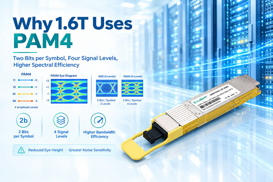
As AI data centers scale toward 1.6T Ethernet, the choice of signal modulation becomes a defining architectural decision. The industry has converged on four-level pulse amplitude modulation (PAM4) as the modulation format for 1.6T optical interconnects. This convergence is not arbitrary—it reflects a careful balance between bandwidth efficiency, signal integrity, power consumption, and manufacturing feasibility.
PAM4 transmits two bits per symbol using four distinct signal levels, doubling the data rate compared to traditional two-level non-return-to-zero (NRZ) signaling at the same symbol rate. For 1.6T systems, this spectral efficiency is essential because it allows engineers to achieve higher aggregate bandwidth without proportionally increasing the symbol rate or the number of parallel lanes.
However, PAM4 introduces significant signal integrity challenges. The four signal levels are packed into the same amplitude swing that NRZ uses for two levels, reducing the eye height by approximately 33% and making PAM4 far more susceptible to noise, jitter, and intersymbol interference. Understanding why 1.6T uses PAM4 requires examining both the bandwidth economics that favor it and the signal processing techniques that make it viable.
1. The Bandwidth Challenge at 1.6T
AI workloads drive unprecedented demand for network bandwidth. Distributed training and large-scale inference require massive data movement between GPUs, servers, and switches. As aggregate switch capacities rise from 51.2T toward 102.4T and beyond, the optical interconnect layer must scale proportionally.
1.6T Ethernet represents a fourfold increase over 400G and a twofold increase over 800G. Achieving this capacity requires either increasing the symbol rate, adding more parallel lanes, or both. Each approach has trade-offs.
Increasing the symbol rate places greater demands on the electrical and optical components. Higher symbol rates require wider bandwidth in drivers, modulators, photodiodes, and transimpedance amplifiers. They also exacerbate signal degradation from jitter, dispersion, and channel loss.
Adding more lanes increases the number of optical channels, fibers, connectors, and packaging complexity. At the scale of modern AI switches, which may support hundreds of optical ports, lane proliferation quickly becomes impractical.
PAM4 offers a middle path: by transmitting two bits per symbol, it doubles the data rate without doubling the symbol rate. This allows 1.6T systems to use 200 Gbps per lane with 8 lanes, rather than requiring 400 Gbps per lane or 16 lanes at 100 Gbps each.
2. PAM4 Fundamentals: Four Levels, Two Bits per Symbol
PAM4 encodes two bits of information into each symbol period by using four distinct amplitude levels. The four levels typically correspond to the bit pairs 00, 01, 10, and 11. At the receiver, the signal is sampled and each sample is mapped back to the nearest of the four levels, recovering two bits of data.
This encoding scheme doubles the spectral efficiency of NRZ. For a given symbol rate, PAM4 delivers twice the bit rate. Alternatively, for a given bit rate, PAM4 requires half the symbol rate of NRZ.
The trade-off is reduced noise margin. With four levels packed into the same peak-to-peak amplitude as NRZ's two levels, the spacing between adjacent levels is one-third that of NRZ. This reduction in eye height makes PAM4 signals more vulnerable to amplitude noise, timing jitter, and reflections.
| Characteristic | NRZ | PAM4 |
|---|---|---|
| Bits per Symbol | 1 | 2 |
| Signal Levels | 2 | 4 |
| Relative Eye Height | 100% | ~33% of NRZ |
| Spectral Efficiency | 1 bit/symbol | 2 bits/symbol |
| SNR Requirement | Lower | Higher (approximately 9.5 dB more than NRZ for equivalent BER) |
| Symbol Rate for 200G/lane | Not practical | ~106 GBaud (with overhead) |
The SNR penalty of PAM4 relative to NRZ is significant. Theoretical analysis shows that under additive white Gaussian noise (AWGN) conditions, PAM4 requires approximately 9.5 dB more SNR than NRZ to achieve the same bit error rate. This penalty is the fundamental cost of doubling spectral efficiency.
3. Why NRZ Cannot Scale to 1.6T
NRZ served Ethernet well from 10G through 400G. At lower data rates, NRZ's simple two-level signaling provided ample noise margin and straightforward signal integrity management. However, as data rates increased, NRZ's limitations became increasingly apparent.
The primary constraint is the bandwidth required for a given data rate. NRZ transmits one bit per symbol, so a 200 Gbps lane requires a 200 GBaud symbol rate. This demands electrical and optical components with bandwidth exceeding 200 GHz, which is difficult and expensive to achieve with practical materials and packaging.
Furthermore, channel loss increases dramatically at higher frequencies. PCB traces, connectors, and cables all exhibit frequency-dependent attenuation that worsens as symbol rates rise. At 200 GBaud, the channel loss becomes prohibitive for NRZ signaling over meaningful distances.
PAM4 alleviates this constraint by halving the symbol rate for a given data rate. A 200 Gbps PAM4 lane operates at approximately 106 GBaud, which is far more manageable for both electrical and optical components. The bandwidth requirements are reduced, and the channel loss at the lower symbol rate is significantly less severe.
4. The Role of PAM4 DSP in 1.6T Systems
PAM4's reduced noise margin necessitates sophisticated signal processing to recover data reliably. This is the role of the PAM4 digital signal processor (DSP), which has become a critical component in 1.6T optical transceivers.
The PAM4 DSP performs several essential functions:
Equalization: Compensates for channel loss and ISI using techniques such as feed-forward equalization (FFE) and decision-feedback equalization (DFE).
Forward Error Correction (FEC): Adds redundancy to the data stream so that errors caused by noise and distortion can be detected and corrected at the receiver.
Clock and Data Recovery (CDR): Extracts timing information from the incoming signal and retimes the data.
Signal Shaping: Applies pre-emphasis and other techniques to optimize the transmitted signal for the channel.
Recent PAM4 DSPs for 1.6T applications are fabricated on advanced CMOS nodes such as 3nm, enabling complex algorithms to be implemented with acceptable power consumption. Broadcom's Taurus BCM83640, for example, is a monolithic 3nm 1.6T PAM4 DSP with an integrated laser driver, designed to support 400 Gbps per lane and lay the groundwork for 3.2T modules.
Marvell's Ara and Nova families similarly target 1.6T and 800G optical transceivers, supporting both Ethernet and InfiniBand applications with 200G PAM4 on both host and line sides.
The DSP's power consumption is a major consideration in AI data centers, where every watt of transceiver power contributes to the total cost of ownership. Advanced CMOS nodes and optimized architectures have helped reduce DSP power, but it remains a significant fraction of module power.
5. SNR Challenges and the Case Against Higher-Order Modulation
Given PAM4's SNR penalty relative to NRZ, one might ask why the industry does not skip directly to PAM6 or PAM8, which offer even higher spectral efficiency. PAM6 transmits approximately 2.58 bits per symbol, and PAM8 transmits 3 bits per symbol, potentially enabling higher data rates at lower symbol rates.
The answer lies in the SNR requirements. Theoretical analysis shows that under AWGN conditions, the SNR gap between PAM4 and PAM6 is approximately 3 dB, and between PAM4 and PAM8 approximately 6 dB. In practical optical systems with limited link budgets, these additional SNR requirements are difficult to meet.
Consider the numbers: with a received SNR of 24 dB, PAM4 can theoretically achieve a bit error rate of 1e-12, while PAM6 can only achieve approximately 1e-6. To achieve reliable operation, PAM6 would require either higher received optical power, stronger FEC, or both—each with cost, power, or latency implications.
| Modulation | Bits per Symbol | Relative SNR Requirement | Symbol Rate for 400G/lane |
|---|---|---|---|
| PAM4 | 2 | Baseline | ~224 GBaud |
| PAM6 | ~2.58 | ~3 dB higher | ~174 GBaud |
| PAM8 | 3 | ~6 dB higher | ~150 GBaud |
The trade-off is clear: PAM6 and PAM8 reduce symbol rate requirements but demand significantly better SNR performance. In practical 1.6T systems, where link budgets are already tight and FEC overhead is constrained by latency requirements, PAM4 offers the best balance of spectral efficiency and implementation feasibility.
6. PAM4 and the Evolution from 400G to 800G to 1.6T
The Ethernet ecosystem has evolved in a way that favors PAM4 continuity across generations. Understanding this progression clarifies why PAM4 remains the standard at 1.6T.
At 400G, early deployments used 8 lanes of 50G PAM4. The 50G PAM4 signaling was well-understood and supported by mature DSP technology. As the industry moved to 800G, the natural evolution was to double the lane rate to 100G PAM4, maintaining the same modulation format and symbol rate family.
For 1.6T, the industry again doubled the lane rate to 200G PAM4. This continuity allowed DSP vendors, optical component manufacturers, and test equipment providers to leverage their investments in PAM4 technology and extend them to higher rates. PAM4 modulation is applied to 1.6TbE, with the baud rate doubling relative to the 800GbE scenario.
Each generation has required incremental improvements in signal integrity, DSP algorithms, and optical component performance, but the fundamental modulation scheme has remained constant. This continuity has accelerated time-to-market and reduced development risk.
An alternative path—switching to PAM6 or PAM8 at 1.6T—would have required a complete re-engineering of DSP algorithms, test methodologies, and optical component specifications. The industry judged this discontinuity to be unnecessary given PAM4's demonstrated scalability.
7. Signal Integrity Considerations for 1.6T PAM4
Operating PAM4 at 200 Gbps per lane (approximately 106 GBaud symbol rate) introduces signal integrity challenges that require careful engineering across the entire link.
7.1 Transmitter Challenges
The transmitter must generate four precisely spaced amplitude levels with sufficient linearity. Laser nonlinearity, modulator nonlinearity, and driver nonlinearity can all distort the signal constellation, reducing the effective eye opening. Advanced DSP techniques, including pre-distortion and nonlinear compensation, help mitigate these effects.
Extinction ratio—the ratio of optical power in the "1" state to the "0" state—becomes more critical in PAM4 systems. With four levels, the outer levels are most vulnerable to compression, and insufficient extinction ratio reduces the separation between levels, degrading BER.
7.2 Channel Challenges
The optical channel introduces dispersion, which causes different frequency components of the signal to travel at different speeds. At 106 GBaud, even small amounts of chromatic dispersion can cause significant ISI. Dispersion compensation, either optical or electronic, is essential.
Fiber nonlinearity, including self-phase modulation and cross-phase modulation, can also degrade PAM4 signals. These effects are more pronounced at higher optical launch powers, creating a trade-off between SNR (which improves with higher power) and nonlinear distortion (which worsens with higher power).
7.3 Receiver Challenges
The receiver must accurately distinguish four signal levels in the presence of noise, ISI, and other impairments. The photodiode and transimpedance amplifier must provide sufficient bandwidth and linearity. Analog-to-digital converters (ADCs) must have enough resolution and speed to capture the signal without significant quantization noise.
Receiver sensitivity for 448 Gbps PAM4 (the lane rate for next-generation 1.6T and 3.2T systems) is approximately 2 dB worse than for 224 Gbps PAM4, requiring improvements in photodiode responsivity, receiver SOA performance, or both.
8. Forward Error Correction and PAM4 Link Budgets
Forward error correction is an integral part of PAM4-based 1.6T systems. FEC adds redundant bits to the data stream, allowing the receiver to correct errors that would otherwise cause link failure. Without FEC, PAM4's reduced noise margin would make reliable operation at 200 Gbps per lane impractical.
Several FEC schemes are used in high-speed Ethernet. KP4 FEC, defined in IEEE 802.3, provides a codeword with approximately 2.7 dB of coding gain. More powerful FEC schemes, such as those with 25% overhead (often denoted as 25% OH SD-FEC), provide higher coding gain at the cost of increased latency and power consumption.
The choice of FEC involves trade-offs among coding gain, latency, power, and implementation complexity. For AI data center applications, where low latency is often critical, there is pressure to minimize FEC overhead. However, reducing FEC strength places greater demands on the optical link budget and component performance.
PAM4's SNR requirements mean that FEC is not optional—it is a fundamental enabler of the technology at 1.6T rates.
9. PAM4 vs. Coherent Detection for 1.6T
Coherent optical transmission, which encodes information in both amplitude and phase of the optical carrier, offers higher spectral efficiency than PAM4. Coherent systems can support higher-order modulation formats such as 16-QAM and 64-QAM, achieving much greater bits per symbol.
However, coherent technology is currently more expensive, more power-hungry, and more complex than direct-detect PAM4 systems. For intra-data-center applications with reaches of 2 km or less, the spectral efficiency advantage of coherent transmission does not justify its cost and complexity.
PAM4 with intensity modulation and direct detection (IM/DD) remains the most cost-effective solution for short-reach AI data center interconnects. Its simplicity, mature ecosystem, and adequate performance for the required distances make it the preferred choice for 1.6T optical interconnects.
10. The Path to 3.2T and Beyond: Is PAM4 Still Viable?
As the industry looks toward 3.2T Ethernet, a critical question arises: can PAM4 scale to 400 Gbps per lane? The answer appears to be yes, but with significant engineering challenges.
Achieving 400 Gbps per lane with PAM4 requires symbol rates of approximately 212 GBaud (after accounting for FEC overhead). This is within reach of advanced DSP and optical component technologies, but the SNR and bandwidth requirements are demanding.
The 400G/lane PAM4 DSP, exemplified by Broadcom's Taurus BCM83640, is designed to support 3.2T optical transceivers and future 204.8T switching capacities. This indicates that the industry expects PAM4 to remain the modulation format of choice well into the 3.2T generation.
Beyond 3.2T, the limits of PAM4 become more apparent. To achieve even higher lane rates with PAM4 would require symbol rates that push the boundaries of semiconductor and optical component technology. At that point, alternative approaches such as coherent detection or higher-order PAM formats (PAM6 or PAM8) may become necessary.
But for 1.6T, and likely for 3.2T, PAM4 offers the best combination of spectral efficiency, implementation feasibility, and ecosystem maturity.
11. Evaluating PAM4 Design Trade-offs for 1.6T Systems
When evaluating PAM4 for a 1.6T system, several factors should be considered to ensure successful implementation.
| Evaluation Factor | What to Confirm |
|---|---|
| Lane Rate | 200G PAM4 per lane for 1.6T (8 lanes) or 400G PAM4 for 3.2T |
| Symbol Rate | Approximately 106 GBaud for 200G per lane, considering FEC overhead |
| FEC Scheme | KP4 or stronger FEC with acceptable latency and power |
| DSP Capability | Equalization, CDR, and error correction performance at target rates |
| Optical Component Bandwidth | Sufficient bandwidth for the symbol rate with adequate roll-off |
| Receiver Sensitivity | Compatible with the link budget and FEC threshold |
| Power Consumption | Total module power including DSP, optics, and laser |
| Thermal Management | Cooling requirements for the module and DSP |
| Interoperability | Compliance with IEEE and OIF standards |
A thorough evaluation should compare PAM4-based 1.6T designs against alternatives, including lower lane rates with more lanes, higher-order modulation formats, and coherent solutions. In most cases, PAM4-based 1.6T will offer the best balance of performance, cost, and ecosystem support.
12. The Future of PAM4 in AI Data Centers
PAM4 has become the de facto modulation format for high-speed optical interconnects from 400G through 1.6T. Its combination of spectral efficiency, implementation feasibility, and ecosystem maturity has made it the standard choice for AI data center networking.
The future of PAM4 depends on the industry's ability to overcome the signal integrity challenges that arise at higher symbol rates. Advances in DSP algorithms, optical component design, and packaging technology will be essential to sustain the PAM4 roadmap toward 3.2T and beyond.
For 1.6T specifically, PAM4 is not merely a choice—it is the enabling technology that makes the data rate practical. Without PAM4's spectral efficiency, achieving 1.6T would require either impractical symbol rates or excessive lane counts. The industry's convergence on PAM4 reflects a collective engineering judgment that its trade-offs are the most favorable for this generation of optical interconnects.
As AI workloads continue to drive bandwidth demand, PAM4 will remain the foundation of high-speed optical networking. Its role in 1.6T systems is a testament to the modulation format's scalability and the engineering community's ability to extract performance from a challenging signal format.
13.Conclusion
1.6T Ethernet uses PAM4 because PAM4 doubles the bits per symbol compared to NRZ, halving the symbol rate required for a given data rate. This reduction in symbol rate is essential for managing channel loss, component bandwidth requirements, and signal integrity at the speeds required for AI data center interconnects.
The choice of PAM4 over NRZ, PAM6, or PAM8 reflects a careful balance. NRZ cannot scale to the symbol rates required for 1.6T. PAM6 and PAM8 offer higher spectral efficiency but demand SNR performance that is difficult to achieve within practical optical link budgets. PAM4 provides the best compromise between efficiency and feasibility.
PAM4 does introduce challenges—reduced eye height, higher SNR requirements, and the need for sophisticated DSP and FEC. However, these challenges are manageable with current technology, and the industry has invested heavily in the PAM4 ecosystem for good reason. For 1.6T and likely for 3.2T, PAM4 is the modulation format that makes high-capacity optical interconnects practical.
 >
>

 >
>
 >
>
 >
>
 >
>
 >
>
 >
>
 >
>