TEL:+86 132 6656 7067




Linear Pluggable Optics (LPO) is an optical transceiver architecture developed to reduce power consumption and latency in high-speed optical links. Unlike conventional DSP-based pluggable optical transceivers, LPO removes the high-power retiming and digital signal processing functions from the module and relies more heavily on the host system's electrical SerDes and linear optical components.
LPO has attracted increasing attention as data center and AI networking systems move toward 800G and 1.6T connectivity. The main architecture uses linear laser drivers on the transmit side and transimpedance amplifiers (TIAs) on the receive side, without a conventional retimer or DSP inside the optical module.
This approach can reduce module power and latency, but it also changes where signal conditioning and channel compensation take place. As a result, LPO performance depends more directly on the host switch ASIC, electrical channel, SerDes, optical engine, and system-level signal integrity.
1. What Is LPO?
LPO stands for Linear Pluggable Optics, also called Linear Pluggable Optical. It is a pluggable optical transceiver architecture in which the module uses relatively simple linear electrical-to-optical and optical-to-electrical components rather than a full retiming DSP inside the transceiver.
A typical LPO transmitter uses a linear laser driver to drive the optical source, while the receiver uses a TIA to convert the photodiode current into an electrical signal. The high-speed signal remains more closely aligned with the host SerDes waveform.
This architecture reduces the amount of digital processing performed inside the optical module and can therefore lower module power consumption and latency.
2. What Are Traditional Optical Transceivers?
Traditional high-speed optical transceivers commonly use a DSP or retimer to process the electrical signal between the host switch and the optical engine.
The DSP can perform functions such as equalization, signal conditioning, retiming, gearbox conversion, PAM4 processing, and other signal-management functions depending on the module architecture.
This processing improves the module's ability to compensate for channel impairments, but the DSP also consumes power and adds processing latency.
3. LPO vs Traditional Optical Transceivers: Basic Difference
| Feature | LPO | Traditional DSP-Based Optical Transceiver |
|---|---|---|
| Module DSP | Normally not used | Common in many high-speed implementations |
| Transmitter | Linear laser driver | DSP / retimer + laser driver or integrated optical engine |
| Receiver | TIA | TIA + DSP / retimer |
| Latency | Very low module processing latency | Higher because of digital processing |
| Module Power | Potentially lower | Generally higher when DSP processing is included |
| Host Dependence | Higher | Lower because more signal conditioning is inside the module |
| Channel Tolerance | More dependent on host electrical channel | DSP can provide additional compensation |
| Typical Application | Short-reach high-speed links | Broad range of optical links |
4. Why Was LPO Developed?
The increasing bandwidth of AI and data center networks has created strong pressure to reduce power per optical bit.
At 800G and 1.6T, a large number of optical ports may operate simultaneously. If every module contains a high-power DSP, the combined module power can become a significant part of the switch's total power consumption.
LPO addresses this issue by moving more of the signal-processing responsibility into the host SerDes and using lower-power linear components inside the optical module.
Marvell's 2024 LPO chipset, for example, combines a 200G-per-lane TIA and laser-driver architecture to enable 800G and 1.6T LPO modules without requiring a conventional DSP inside the optical module.
5. LPO Electrical Architecture
The fundamental LPO architecture is based on a direct high-speed electrical connection between the host SerDes and the optical module's linear driver or receiver circuitry.
On the transmit side, the host generates the high-speed PAM4 electrical signal. The linear driver amplifies or conditions the signal sufficiently to drive the optical transmitter.
On the receive side, the optical receiver detects the signal and the TIA converts the photodiode current into an electrical waveform that is returned to the host SerDes.
This eliminates the traditional digital processing stage between the host SerDes and the optical components.
6. What Does the DSP Do in a Traditional Module?
A conventional high-speed optical DSP can perform several functions that help compensate for electrical and optical channel limitations.
Depending on the design, these functions can include transmitter equalization, receiver equalization, clock recovery, retiming, gearbox functions, modulation processing, forward-error-correction-related processing, and other signal-conditioning functions.
Because these functions are performed inside the module, the host switch can communicate with a wider range of electrical channels and optical module implementations.
7. What Changes When the DSP Is Removed?
Removing the module DSP changes the location of signal processing rather than eliminating the need for signal integrity management.
In LPO, more responsibility is transferred to the switch ASIC, host SerDes, PCB channel, connectors, and linear optical components.
The host must therefore provide sufficient equalization and signal quality to drive the optical module and receive a usable signal from it.
This is one of the most important differences between LPO and conventional DSP-based optics.
8. LPO Linear Laser Driver
The linear laser driver is a key component of an LPO transmitter.
Instead of receiving a heavily processed digital waveform from a module DSP, the linear driver receives the electrical signal directly from the host interface and drives the optical source.
The driver must preserve the amplitude and waveform characteristics required for high-speed PAM4 transmission while providing enough electrical swing and bandwidth for the selected optical transmitter.
Driver linearity and bandwidth therefore have a direct effect on the quality of the resulting optical signal.
9. LPO Receiver and TIA
On the receive side, an LPO module typically uses a photodetector and TIA without a conventional module DSP.
The photodetector converts the optical signal into a photocurrent. The TIA amplifies and converts this small current into an electrical voltage waveform that is sent directly toward the host receiver.
The host SerDes then performs the required electrical signal processing and equalization.
10. LPO and PAM4 Signaling
LPO is closely associated with high-speed PAM4 signaling.
PAM4 uses four signal levels and can represent two bits per symbol. This allows higher data rates to be transmitted at practical symbol rates compared with traditional NRZ signaling.
However, PAM4 has smaller voltage separation between adjacent signal levels. As a result, noise, crosstalk, insertion loss, reflections, and nonlinear distortion have a stronger influence on link performance.
Because LPO provides less signal processing inside the module, the quality of the host electrical channel becomes especially important.
11. 800G LPO
800G is one of the main application areas for LPO.
An 800G LPO module can use eight approximately 100G-class electrical lanes and optical channels. Depending on the optical architecture, the module can use DR8, FR4, 2xFR4, AOC, or other configurations.
OIF demonstrations have included 800G LPO solutions using OSFP and QSFP-DD-family form factors, while vendors have demonstrated both silicon photonics and other optical architectures in LPO designs.
12. 1.6T LPO
LPO has also progressed toward 1.6T optical connectivity.
A 1.6T architecture can use eight approximately 200G-class electrical lanes. This places greater requirements on both the host SerDes and optical engine.
Marvell announced a 200G-per-lane LPO chipset for 800G and 1.6T applications and later demonstrated a 1.6T silicon photonics light engine in an OSFP LPO module.
At 1.6T, the power savings from removing a conventional module DSP can become increasingly important, but so do the requirements for host-side signal integrity and thermal design.
13. LPO Power Consumption
Power reduction is one of the primary reasons for considering LPO.
A conventional DSP consumes power while performing high-speed signal processing. Removing the DSP and retimer from the optical module can reduce module power.
OIF LPO demonstrations have reported substantially lower power for linear architectures than conventional retimed optical links. Individual commercial products have reported module power below 8W for certain 800G LPO designs.
Actual power consumption varies with optical architecture, laser technology, driver, TIA, temperature, and operating conditions, so a specific product datasheet should be used for final comparison.
14. LPO Latency
LPO can reduce module processing latency because the high-speed data does not pass through a full DSP and retiming pipeline inside the optical module.
The remaining latency is primarily associated with the optical path, analog components, electrical interconnects, host SerDes, and system architecture.
Vendor demonstrations have reported sub-nanosecond module latency for some LPO products. Actual end-to-end network latency depends on the complete system rather than the optical module alone.
15. LPO Signal Integrity
Signal integrity is one of the main engineering challenges of LPO.
Because the module provides less digital compensation, the electrical channel between the switch ASIC and module must maintain a sufficiently clean signal.
PCB trace length, insertion loss, connector loss, via transitions, return loss, crosstalk, package parasitics, and impedance discontinuities can all affect the eye quality of a PAM4 signal.
The host SerDes must also provide appropriate equalization to compensate for the remaining channel impairments.
16. Host SerDes Requirements
The host SerDes plays a more important role in LPO than in many conventional DSP-based optical architectures.
The switch ASIC must be capable of driving the electrical channel and recovering the returned PAM4 signal with the required margin.
The host SerDes architecture, transmitter equalization, receiver equalization, channel loss budget, and interoperability with the selected linear driver and TIA all affect the final performance.
For this reason, LPO is often evaluated as a complete ASIC-to-module channel rather than simply as an optical transceiver.
17. LPO Channel Length
The electrical channel between the switch ASIC and LPO module should generally be minimized.
A shorter PCB route reduces insertion loss and other high-frequency impairments.
This makes module cage placement, PCB stack-up, connector design, via optimization, and switch board layout important parts of an LPO platform.
The optical reach of an LPO link can still be hundreds of meters or kilometers depending on the optical design. The critical channel-length issue is primarily the high-speed electrical path between the host and optical engine.
18. Optical Reach of LPO
LPO is not limited to one optical reach.
Short-reach 800G DR8 solutions can be designed for several hundred meters over single-mode fiber. Other LPO architectures can use WDM to provide links around 2km.
However, LPO is generally most attractive for relatively short optical links where the benefits of low power and low latency outweigh the reduced electrical compensation capability.
OIF demonstrations have included 800G linear optical solutions at 10 meters, while commercial LPO examples have included approximately 500m DR8 and 2km FR4-class configurations.
19. LPO vs Traditional DSP for Link Reach
Traditional DSP-based optical transceivers can support a broad range of distances because the DSP provides additional electrical signal processing.
LPO has less compensation inside the module and therefore tends to be more dependent on the host electrical channel.
This does not mean that LPO can only support very short optical links. Rather, the practical LPO reach depends on the optical engine, link budget, host channel, switch SerDes, and selected transmission architecture.
20. LPO and Optical Link Budget
Optical link budget remains important for LPO because the optical side of the connection still consists of a transmitter, fiber, passive losses, and receiver.
The difference is mainly on the electrical side of the module architecture.
For an LPO system, the optical power budget should still consider transmitter output power, receiver sensitivity, fiber attenuation, connector loss, passive optical components, and system margin.
An optical link can therefore have sufficient optical power budget while still failing because of insufficient electrical signal integrity.
21. Electrical Margin vs Optical Margin
One of the important concepts in LPO design is the distinction between optical margin and electrical margin.
Optical margin describes how much received optical power remains above the receiver sensitivity after accounting for link loss.
Electrical margin describes how much signal quality remains after electrical channel impairments such as insertion loss, crosstalk, reflections, and noise.
Traditional DSP-based modules can provide additional electrical compensation. LPO depends more heavily on maintaining sufficient electrical margin in the host channel.
22. LPO and BER
Bit Error Rate is a critical performance metric for LPO systems.
Because LPO uses less digital processing inside the module, the pre-FEC electrical and optical error performance can be more sensitive to channel conditions.
Different vendors have demonstrated low pre-FEC BER in LPO configurations, but BER depends heavily on the complete implementation.
Final system validation should therefore evaluate the actual switch, module, PCB, cable, optical path, and host configuration rather than relying only on the module specification.
23. LPO and FEC
Forward Error Correction (FEC) is normally implemented at an appropriate layer of the network system rather than relying on the optical module DSP alone.
The presence or absence of a module DSP does not automatically determine whether a link uses FEC.
A network system can use LPO while relying on the host ASIC and network protocol architecture for the required FEC functionality.
This is an important distinction because removing the module DSP does not mean that the complete link operates without error correction.
24. LPO and Retimers
A traditional retimed optical transceiver can recover and retransmit the electrical signal inside the module.
LPO removes this module-level retiming function in favor of a more direct linear signal path.
The trade-off is lower module processing power and latency versus greater dependence on the host SerDes and electrical channel.
Some emerging architectures, including linear receive and retimed transmit approaches, attempt to provide an intermediate solution between fully linear and fully retimed designs.
25. LPO vs LRO
LRO, or Linear Receive Optics, is an architecture in which the receiver side remains linear while some retiming or processing capability is retained on the transmit side.
This creates a compromise between a fully linear module and a fully DSP-based module.
The exact definition and implementation of LRO can vary between industry discussions and product architectures, so the specific module datasheet should be checked.
26. LPO vs HRO
HRO, or Half-Retimed Optics, describes another intermediate architecture in which only part of the optical data path uses retiming or digital processing.
The objective is to balance power consumption and signal integrity.
OIF demonstrations have included both LPO and retimed-transmit/linear-receive architectures, showing that the industry is evaluating multiple intermediate solutions between fully DSP-based and fully linear optics.
27. LPO vs Traditional DSP-Based Optics
| Parameter | LPO | Traditional DSP-Based Optics |
|---|---|---|
| Module DSP | No conventional DSP | Commonly included |
| Retiming | No module retimer | Generally available |
| Power | Lower module power potential | Higher due to DSP processing |
| Latency | Very low module latency | Higher processing latency |
| Electrical Channel Requirement | Tighter | More tolerant |
| Host SerDes Dependence | High | Lower |
| System Flexibility | More platform-specific | Broad module compatibility |
| Typical Link | Short-reach high-speed connections | Broad reach and application range |
28. LPO and Silicon Photonics
LPO and Silicon Photonics are complementary technologies.
LPO describes the electrical architecture and signal-processing approach of the optical module. Silicon Photonics describes how optical functions are integrated into a photonic integrated circuit.
An LPO module can therefore use a silicon photonics transmitter and receiver while remaining linear on the electrical side.
OIF and commercial demonstrations have included LPO modules using silicon photonics-based optical engines.
29. LPO and InP EML
LPO can also use InP-based optical components.
For example, an LPO architecture can use a linear laser driver to drive an InP EML or other high-speed optical transmitter.
The optical technology and the electrical architecture are therefore separate design decisions.
This means that LPO should not be interpreted as being limited to silicon photonics or to one particular laser technology.
30. LPO and VCSEL
VCSEL technology can also be combined with linear-drive architectures for suitable short-reach applications.
However, the choice between VCSEL, EML, silicon photonics, and other optical technologies depends on wavelength, fiber type, reach, lane rate, optical power, and module requirements.
The LPO architecture itself primarily concerns the electrical interface and signal-processing approach.
31. LPO in AI Data Centers
AI data centers are one of the main environments where LPO is being considered.
GPU and accelerator clusters can require large numbers of high-speed connections, increasing the importance of power efficiency and latency.
LPO can reduce optical module power and module processing latency, which can be valuable in short-reach scale-up and scale-out connections.
Marvell specifically positions its LPO technology for short-reach AI compute fabric connections, while current optical vendors have demonstrated 800G and 1.6T LPO modules for AI networking applications.
32. LPO for GPU-to-GPU Connectivity
High-speed optical links can be used in architectures connecting GPUs, accelerators, servers, and switches.
For relatively short links, LPO can provide low-power connectivity without placing a full DSP in every optical module.
The suitability of LPO depends on whether both ends of the link use compatible electrical architectures and whether the host platforms can maintain sufficient signal quality.
33. LPO for Switch-to-Switch Connections
LPO can also be used for switch-to-switch connections where low latency and power efficiency are important.
Short-reach 800G DR8 and related architectures can provide high bandwidth over single-mode fiber while maintaining a linear electrical path.
For longer links, traditional DSP-based transceivers may provide additional signal conditioning and broader reach options.
34. LPO and Data Center Power Density
The cumulative power consumption of optical modules can become significant in large switches.
For example, a switch with dozens of 800G ports may contain a large number of active optical modules. Reducing several watts per module can therefore create a meaningful reduction in aggregate power.
The actual system benefit depends on module count, operating mode, host SerDes power, cooling architecture, and whether the power used elsewhere in the system increases because more processing is moved into the switch ASIC.
35. LPO and Thermal Design
Lower module power can simplify transceiver thermal management, but it can also move some power consumption into the host switch ASIC.
This means LPO should be evaluated using a system-level thermal model rather than by module power alone.
The switch ASIC, SerDes, PCB, optical cages, module heat sinks, fans, and airflow all contribute to the overall thermal environment.
36. LPO and Host Switch Design
LPO can influence the design of the host switch more strongly than traditional DSP-based optics.
The host system must provide appropriate electrical signal quality, equalization, power delivery, firmware support, and module management.
High-speed PCB routing becomes particularly important because the direct electrical connection between the ASIC and module has less tolerance for channel impairments.
37. LPO and Interoperability
Interoperability is an important consideration for LPO because the module relies more heavily on the host electrical interface.
A traditional DSP-based module can often provide additional signal conditioning that helps accommodate differences between hosts.
LPO requires tighter matching between the switch SerDes, module linear driver and TIA, PCB channel, connector, and optical engine.
This is why multi-vendor LPO interoperability testing is particularly important.
38. LPO and Module Management
LPO modules still require a management interface even though they do not contain a conventional DSP.
Management functions can include module identification, monitoring, alarms, temperature, voltage, optical power, and other parameters depending on the implementation.
CMIS can be used for module management in LPO products, allowing the host system to communicate with the optical module through a standardized management architecture.
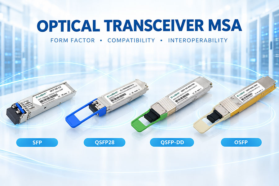
39. LPO and Optical Module Form Factors
LPO is an architecture rather than a physical form factor.
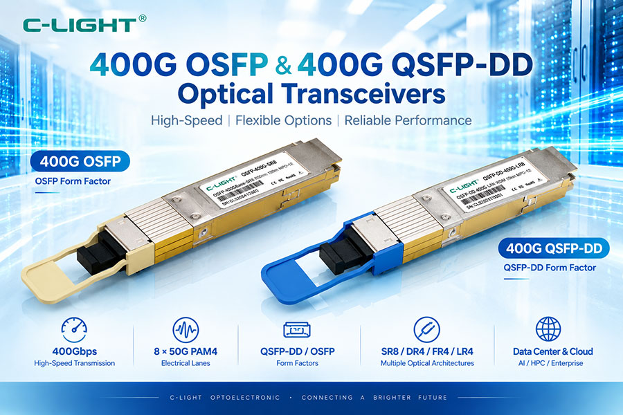
An LPO optical engine can be packaged in different pluggable form factors, including OSFP and QSFP-DD-family modules, depending on the host platform.
Therefore, LPO should not be confused with OSFP or QSFP-DD. OSFP and QSFP-DD define the module and host interface, while LPO defines how the optical module handles high-speed electrical signals.
40. LPO vs OSFP
OSFP and LPO describe different aspects of an optical system.
OSFP is a pluggable form factor with a defined mechanical and electrical interface. LPO is a linear-drive optical architecture that can be implemented inside an OSFP module.
An 800G OSFP module can therefore be either DSP-based or LPO depending on its internal architecture.
41. LPO vs QSFP-DD
QSFP-DD is another physical pluggable form factor that can be used for high-speed LPO modules.
Both QSFP-DD and OSFP can accommodate high-speed LPO designs when the host equipment supports the required electrical lane rate and module architecture.
The choice of QSFP-DD or OSFP is therefore primarily a platform and mechanical decision, while the choice of LPO concerns the electrical and optical implementation inside the module.
42. LPO and Optical Testing
LPO modules require the same basic optical testing as other high-speed transceivers, including transmitter output power, receiver sensitivity, optical eye quality, wavelength characteristics, BER, temperature performance, and power consumption.
However, LPO also requires more attention to the host electrical channel.
Testing should therefore include ASIC-to-module channel measurements, PAM4 eye quality, electrical insertion loss, equalization performance, and system-level interoperability.
43. LPO Production Qualification
Production qualification must verify both the module and the host platform.
Optical module manufacturers can test the transmitter and receiver characteristics independently, but final LPO qualification should also validate operation with the intended host SerDes and electrical channel.
This is particularly important because an LPO module that performs well on one switch platform may have different margins on another platform with a different PCB or SerDes implementation.
44. LPO Reliability
LPO does not eliminate the reliability requirements of high-speed optical transceivers.
Lasers, photodiodes, TIAs, laser drivers, optical coupling structures, fiber interfaces, and electronic components must operate reliably across the specified temperature and environmental range.
Because the module has less digital processing, the long-term performance of the linear electrical components and their interaction with the host platform is particularly important.
45. LPO Cost Considerations
Removing a DSP can reduce module component count and power consumption, but overall system cost depends on more than the optical module bill of materials.
The host ASIC and SerDes may require more advanced equalization and electrical performance. The PCB may also require lower-loss materials and more carefully controlled routing.
Therefore, the correct comparison is between the total system cost rather than simply comparing the cost of an LPO module with a DSP-based module.
46. LPO Deployment Limitations
LPO is particularly sensitive to the host electrical environment.
If the PCB channel is too long or has excessive insertion loss, crosstalk, or reflections, the host SerDes may not be able to recover the signal with sufficient margin.
Network designs that require wide optical reach, strong platform interoperability, or highly flexible module replacement may also require architectures with more signal processing inside the module.
These considerations do not prevent LPO deployment, but they make system validation more important.
47. LPO vs Traditional Optical Transceivers for Different Applications
| Application | LPO | Traditional DSP-Based Optics |
|---|---|---|
| Short AI Network Links | Suitable for compatible platforms | Suitable |
| GPU / Accelerator Interconnect | Suitable for short-reach systems | Suitable |
| 800G Data Center | Supported in selected architectures | Widely used |
| 1.6T Short-Reach | Emerging | Supported depending on platform |
| Long-Reach Optical Link | Less commonly targeted | Broadly supported |
| Multi-Vendor Host Environment | Requires careful validation | Established interoperability model |
| Lowest Module Power | Architecture specifically targets lower power | DSP adds module power |
| Lowest Module Latency | Very low | Higher due to module processing |
48. LPO and Traditional Optics Can Coexist
LPO is not necessarily a replacement for every DSP-based optical transceiver.
Different network links have different requirements. Short-reach AI connections may prioritize power and latency, while longer links or systems requiring greater host flexibility may prioritize additional signal conditioning.
For this reason, LPO and traditional DSP-based optics can coexist within the same broader optical networking ecosystem.
49. Future Development of LPO
LPO development is closely tied to the evolution of host SerDes technology.
As switch ASICs move to higher electrical lane rates, the ability of the host SerDes to compensate for PCB and connector losses becomes increasingly important.
At the same time, linear drivers and TIAs are evolving toward 200G-per-lane and higher-speed operation. Silicon photonics, InP lasers, EMLs, and other optical technologies can all be combined with LPO architectures.
The industry is also evaluating intermediate architectures such as LRO and HRO to balance the power advantages of linear optics with the signal-integrity advantages of partial retiming.
50. Conclusion
LPO and traditional DSP-based optical transceivers use different approaches to high-speed optical connectivity. Traditional modules place more signal processing inside the optical transceiver, while LPO moves more of that responsibility to the host SerDes and uses linear drivers and TIAs in the module.
The main benefits of LPO are lower module power and very low module latency. These characteristics make LPO particularly relevant to short-reach 800G and emerging 1.6T AI networking applications.
The main engineering trade-off is increased dependence on the host electrical channel. PCB loss, connector performance, SerDes equalization, crosstalk, reflections, and system interoperability become more important because the module provides less digital compensation.
LPO is also independent of a specific optical technology or form factor. An LPO module can use silicon photonics, InP-based optical devices, or other optical technologies and can be packaged in OSFP or QSFP-DD-family form factors.
For future high-speed optical networks, LPO, traditional DSP-based optics, LRO, HRO, and other architectures may serve different portions of the network. The appropriate architecture depends on bandwidth, optical reach, power, latency, host SerDes capability, thermal conditions, interoperability, and system requirements.
 >
>

 >
>
 >
>
 >
>
 >
>
 >
>
 >
>
 >
>