TEL:+86 158 1857 3751


With the explosive growth in bandwidth demand for data center interconnects, telecommunications core networks, and cloud services, 100G Ethernet has become the mainstream of next-generation network infrastructure. Among the various 100G optical modules, the QSFP28 100G ER4 stands out for its ultra-long transmission distance of 40 kilometers, making it an ideal choice for connecting campus networks, metropolitan area networks, and critical data center nodes. However, faced with a market of numerous brands and varying specifications, how can you make a wise choice? This article provides a comprehensive selection guide focusing on three core dimensions: Compatibility, Power Consumption, and Cabling.
Chapter 1: In-Depth Analysis of Compatibility – The Key to Ensuring Plug-and-Play
Compatibility is the most common pain point in network upgrades or expansions. If a module cannot be recognized and operated stably by a switch or router, its performance parameters become meaningless.
1.1 Coding and Protocol: Unifying the Underlying Language
First, ensure the selected ER4 module supports the industry-standard 4WDM-10 technology. This technology uses four wavelengths (approximately 1295, 1300, 1305, 1310nm) multiplexed over a single-mode fiber, achieving 100G transmission through PAM4 modulation. Verify that the module protocol matches your device port requirements (typically 100GBASE-ER4).
1.2 Brand Interoperability: Bridging Vendor Barriers
Even when adhering to the same standard, different network equipment vendors (such as Cisco, Arista, Juniper, Huawei, etc.) may have specific checks for the module's microcode or DDM (Digital Diagnostic Monitoring) information. Best practices include:
Prioritize modules certified or listed by the equipment manufacturer: Consult the official Compatibility Matrix documentation of the device.
Consider reputable third-party compatible modules: Many professional optical module suppliers offer "multi-vendor compatible" products that have undergone extensive interoperability testing, often with better cost-effectiveness. Before ordering, be sure to request or verify an Interoperability Test Report for your specific device model.
1.3 DDM/DOM Functionality: A Visual Management Window
Ensure the module has full DDM/DOM functionality, enabling real-time monitoring of temperature, voltage, bias current, and transmit/receive optical power. This not only facilitates daily operation, maintenance, and fault预警 but is also crucial for judging the module's health. Checking whether this information can be correctly read in the management interface is a vital step in verifying compatibility.
Chapter 2: Balancing Power Consumption and Heat Dissipation – The Lifeline of Stable Operation
The power consumption of 100G optical modules is significantly higher than that of lower-rate modules. The ER4, requiring drivers for long-distance transmission lasers, has relatively high power consumption within the QSFP28 family.
2.1 Power Consumption Range and Impact
The typical maximum power consumption of a QSFP28 100G ER4 module generally ranges from 4.5W to 5.5W. High power consumption has two direct impacts:
●Local High Temperature: Increased heat generation from the module itself affects performance and lifespan.
●Total Rack Power Consumption and Thermal Design: In high-density deployments, the cumulative power consumption of multiple modules places higher demands on rack power supply and air conditioning cooling.
2.2 Thermal Considerations and Optimization Recommendations
●Equipment Side: Ensure your network device (switch/router) provides sufficient airflow (typically side-to-side ventilation) for the QSFP28 ports. Check the device specifications for the maximum operating temperature supported for optical modules.
●Deployment Side: Maintain clear front-to-back airflow paths within the rack to prevent performance degradation or crashes due to module overheating. For extremely high-density deployments, consider module models with optimized designs such as heat sinks.
●Selection Trend: Pay attention to and prioritize products that utilize more advanced DSP (Digital Signal Processing) technology and low-power laser designs. These modules can control maximum power consumption to 4.5W or even lower while guaranteeing performance, offering significant advantages in long-term energy savings and stability.
Chapter 3: Planning the Cabling Scheme – Building a Solid Bridge for Performance
Correct fiber optic cabling is the foundation for the ER4 module to achieve its 40km capability. Any oversight can lead to insufficient link budget or signal degradation.
3.1 Fiber Type: Must be Single-Mode
The QSFP28 ER4 must be used with Single-Mode Fiber (SMF, G.652.D or better). Never mistakenly connect it to multi-mode fiber, as communication will be impossible.
3.2 Connector Type: LC Duplex is Standard
ER4 modules use the standard Duplex LC interface. Prepare matching LC-LC single-mode fiber patch cables or patch panel modules.
3.3 Link Budget and Loss Calculation: The Core Computation
This is the key to ensuring successful long-distance transmission. The Link Budget for an ER4 module is typically around 23dB.
You need to calculate the Total Insertion Loss of the entire fiber link, including:
●Fiber Attenuation Itself: Standard single-mode fiber has a typical attenuation of 0.35 dB/km in the 1310nm window. Attenuation for a 40km distance is approximately 14 dB.
●Fusion Splice or Connector Loss: Each fusion splice is about 0.1 dB; each connector pair (mated pair) is about 0.75 dB.
●Design Margin: Reserve at least 3dB of margin for fiber aging, temperature variations, etc.
●Calculation Formula: Total Loss = Fiber Length(km) 0.35 + Number of Connector Pairs 0.75 + Number of Fusion Splices 0.1 + Design Margin(≥3dB)
●Example: A 35km link uses 2 connector pairs and has 2 fusion splices, with a design margin of 3dB.
Total Loss ≈ (35 0.35) + (2 0.75) + (2 0.1) + 3 ≈ 12.25 + 1.5 + 0.2 + 3 ≈ 16.95 dB
The result (16.95 dB) is well below the module's link budget (23 dB), so this design is safe and reliable. Always ensure your calculated total loss is less than the module's specified link budget.
3.4 Fiber Management and Cleaning
For high-speed, long-distance transmission, fiber end-face cleanliness is paramount. Microscopic dust can cause several dB of additional loss. Before inserting the module, always inspect and clean the fiber end-faces and the module's optical ports using a professional fiber inspection microscope and cleaners.
0℃~70℃ 丨 TX:-2dBm~5dBm 丨 RX < -21.4dBm 丨 < 5.5w丨Factory warranty |
CL100GQSFPER4 |
●Compliant with QSFP28 Standard:SFF-8661 Rev 2.5, SFF-8636 Rev 2.10a ●High speed I/O electrical interface (CAUI-4) compliant with IEEE 802.3bm-2015 ●Compliant with 100GBASE-ER4 Lite standard ●Single 3.3V Supply Voltage ●Maximum power consumption 5.5 W at 70ºC Case Operating Temperature ●Single 3.3V power supply ●LAN WDM EML laser and APD Receiver ●Universal QSFP28 MSA package with duplex LC connector ●Two Wire Serial Interface with Digital Diagnostic Monitoring ●Complies with EU Directive 2011/65/EU (RoHS compliant) ●Class 1 Laser |
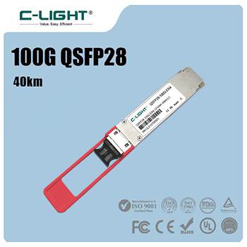
Specification | |||
| Number | CL100GQSFPER4 | Vendor | C-LIGHT |
| Form Factor | QSFP28 | Data Rate Max | 103.125Gbps (4x 25.78Gbps) |
| Wavelength | 1310nm | Distance | 40km |
| Connector | LC | Media | SMF |
| Transmitter Type | 4 x LAN WDM EML | Receiver Type | PIN |
| TX Power | -2dBm~5dBm | Receiver Sensitivity | < 21dbm |
| Power Budget | 19dBm | Receiver Overload | < -4.5dBm |
| Power Consumption | ≤5.5W | Extinction Ratio | >8dB |
| DDM/DOM | Supported | Industrial Temperature Range | 0 to 70°C |
| CDR | TX & RX Built-in CDR | FEC Function | No |
| Protocols | SFF-8661 Rev 2.5, SFF-8636 Rev 2.10a,QSFP28 MSA and IEEE 802.3bm-2015 | Warranty | 3 Years |
Summary and Quick Checklist
When selecting a QSFP28 100G ER4 optical module, follow these steps:
1. Confirm Compatibility: Check the equipment vendor's compatibility list or request an interoperability test report for third-party modules.
2. Verify Protocol and Features: Confirm it is 100GBASE-ER4 and supports full DDM/DOM functionality.
3. Evaluate Power Consumption: Prioritize energy-efficient models with maximum power consumption ≤ 4.5W, and ensure the device's thermal design can meet the demand.
4. Plan Cabling Precisely:
Use G.652.D or better single-mode fiber.
Use duplex LC connectors.
Core Step: Calculate the total link loss in detail, ensuring it is less than the module's link budget (~23dB) with sufficient margin.
5. Perform Pre-Installation Cleaning: Always clean all fiber connection end-faces.
By systematically focusing on the three pillars of Compatibility, Power Consumption, and Cabling, you can not only select a stable and reliable QSFP28 100G ER4 optical module for your network but also build a future-proof, high-performance, and easily maintainable long-distance 100G fiber link, laying a solid foundation for smooth business operations.

 >
>

 >
>
 >
>
 >
>
 >
>
 >
>