TEL:+86 158 1857 3751


At the core of modern data centers and communication networks, optical transceivers serve as the critical hub for electro-optical conversion. Their stability directly determines network quality. Frame errors, superficially manifesting as packet errors, are in reality a direct manifestation of systemic imbalance across multiple dimensions including optical, electrical, temporal, and logical aspects.
I. What Are Frame Errors?
In optical communication systems, data is segmented into standardized "frames" for transmission, each containing payload data and control information. Frame errors occur when the frame structure received at the receiving end does not match the original frame sent from the transmitting end. This includes, but is not limited to, frame sync loss, frame alignment errors, and frame check sequence (FCS) errors.
Imagine reading an important letter where every few lines there are typos, scrambled word order, or misplaced paragraphs—this is how frame errors manifest in the data world. At the system level, frame errors lead to packet loss, reduced transmission efficiency, degraded service quality, and in severe cases, can even cause link failure.
II. Multidimensional Cause Analysis of Frame Errors
Frame errors in optical transceivers are not caused by a single factor but are the combined result of issues related to equipment, environment, and system interaction.
1. Inherent Quality Issues of the Optical Transceiver
Chip Performance Defects: Subpar performance of laser drivers, limiting amplifiers, or clock and data recovery (CDR) chips can cause signal distortion.
Aging Optical Components: Performance degradation of lasers or photodiodes over time leads to unstable optical power.
Manufacturing Process Deviations: Insufficient precision in fiber coupling alignment causes excessive optical path loss or increased back reflection.
2. Signal Integrity Issues
Transmitter-side Issues: Factors like insufficient extinction ratio, improper modulation amplitude, and excessive signal jitter degrade signal quality.
Receiver-side Issues: Decreased receiver sensitivity, insufficient noise margin, and weak clock recovery capability impair correct signal identification.
Accumulation of Signal Impairments: Transmission impairments such as dispersion and nonlinear effects accumulate over long distances, eventually exceeding system tolerance.
3. Environmental and Physical Factors
Temperature Effects: High temperatures cause laser wavelength drift and performance degradation, while low temperatures may lead to difficult module startup.
Vibration and Stress: Mechanical vibration can loosen fiber optic connectors, introducing additional loss and reflection.
Cleanliness Issues: Contaminated optical interfaces are a common cause of frame errors; even microscopic dust can cause significant optical power loss.
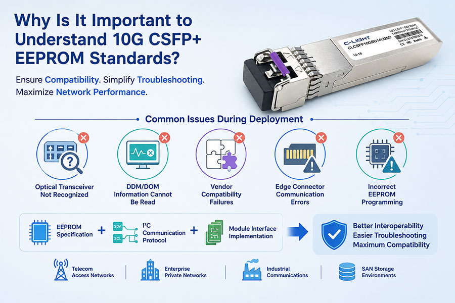
4. System Compatibility and Configuration Issues
Rate and Protocol Mismatch: Compatibility issues between the optical transceiver and switch equipment regarding transmission rate, encoding scheme, or communication protocol.
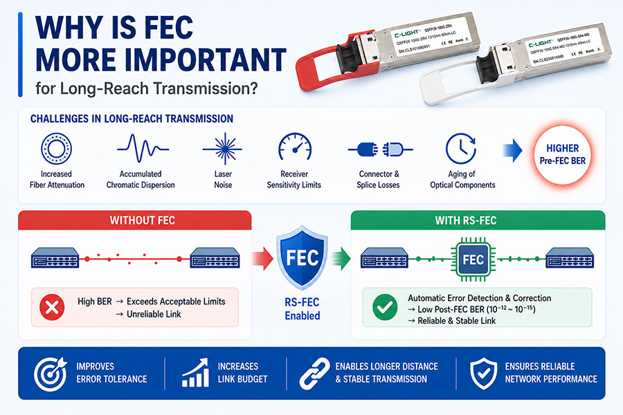
Incorrect Configuration Parameters: Software-level issues such as improper Forward Error Correction (FEC) settings or incorrect equalizer configuration.
Power Supply Quality Issues: Power supply noise and voltage fluctuations can interfere with the normal operation of the transceiver's internal circuitry.
III. Diagnostic Methods and Procedures for Frame Errors
A systematic diagnostic approach helps quickly locate the fault point when facing frame error issues:
1. Basic Checks
Review system alarm information to confirm frame error counts and error types.
Check the Digital Diagnostic Monitoring (DDM) parameters of the optical transceiver, focusing on received optical power, transmitted optical power, temperature, and supply voltage.
Verify the transceiver's compatibility with the equipment vendor's list to ensure the hardware combination is certified.
2. Signal Quality Assessment
Use an eye diagram analyzer to assess signal quality, observing key parameters like eye opening and jitter.
Test the Bit Error Rate (BER) to quantitatively evaluate link transmission performance.
Perform end-to-end loopback tests to segment and locate the faulty section.
3. Environmental and Physical Inspection
Clean fiber optic connector end faces and inspect end-face quality using a professional microscope.
Check if the fiber bend radius complies with standards to avoid loss from excessive bending.
Measure ambient temperature to ensure it is within the module's operating range.
IV. Solutions and Preventive Measures
1. Hardware-Level Strategies
Select high-quality optical transceivers that have undergone rigorous testing; avoid using low-cost modules from unknown sources.
Deploy appropriate optical power budget design to ensure sufficient system margin.
Consider using modules or systems with dispersion compensation functionality for long-distance transmission scenarios.
2. System Configuration Optimization
Correctly configure the Forward Error Correction (FEC) function to improve system fault tolerance.
Adjust transmit power based on the actual transmission distance to avoid overload or insufficiency.
Enable built-in system features like link training and adaptive equalization.
3. Enhanced Operation and Maintenance Management
Establish a regular preventive maintenance plan, including cleaning inspections and performance tests.
Implement temperature monitoring and management systems to ensure equipment operates in a suitable environment.
Establish an optical transceiver lifecycle management system for timely replacement of aging modules.
4. Application of Technological Innovation
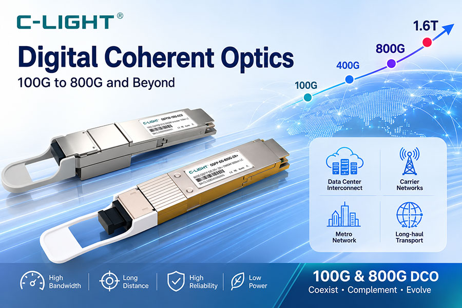
Consider adopting more advanced coherent optical communication technology to improve system resilience against impairments.
Deploy intelligent optical network systems to achieve fault prediction and automatic repair.
Apply AI algorithms to analyze historical fault data for early identification of potential risk patterns.
As data rates evolve towards 800G and 1.6T, the signal integrity challenges faced by optical transceivers will become more severe. Innovative solutions like silicon photonics and co-packaged optics are reshaping transceiver design philosophies. In the future, intelligent and integrated optical transceivers will possess stronger self-diagnostic and adaptive capabilities, enabling real-time status monitoring and dynamic adjustment of operational parameters to fundamentally reduce the probability of frame errors.
Simultaneously, the continuous improvement of industry standards will enhance equipment interoperability. Standardization bodies like IEEE, ITU-T, and OIF are developing stricter test specifications for optical transceivers, driving continuous improvement in product quality across the industry.


 >
>

 >
>
 >
>
 >
>
 >
>
 >
>
 >
>
 >
>
 >
>
 >
>