TEL:+86 132 6656 7067




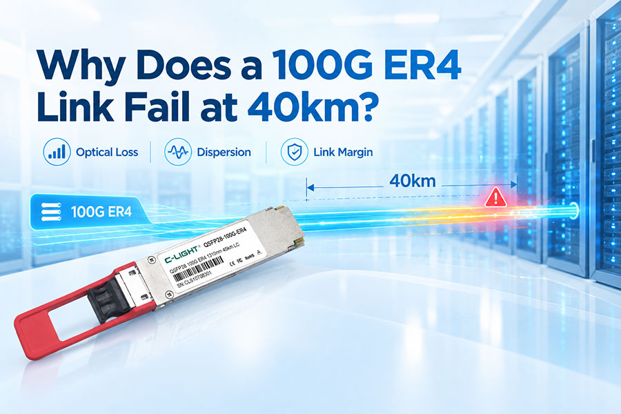
100G ER4 link can fail near 40km even when the transceiver is rated for 40km. The actual result depends on fiber loss, connector quality, dispersion, optical power, receiver sensitivity, and the total link budget.
1. Why Can a 100G ER4 Link Fail at 40km?
40km is a maximum reach under defined optical conditions, not a guarantee that every installed 40km fiber path will operate successfully. Long links require sufficient optical margin from the transmitter to the receiver.
2. 40km Is an Engineered ER4 Link
100GBASE-ER4 is generally specified for operation up to 30km, while links beyond 30km up to 40km are treated as engineered links. The fiber attenuation and other channel conditions must remain within the applicable budget.
3. Optical Power Budget Is the First Check
The optical power budget represents the difference between available transmitter power and the receiver sensitivity. Fiber attenuation, connector loss, splice loss, dispersion penalties, and other impairments consume this margin.
4. Fiber Attenuation Can Exceed the Expected Value
Fiber loss is not identical on every installed route. Older fiber, poor-quality sections, environmental conditions, and wavelength-dependent attenuation can increase total loss and reduce the available margin at 40km.
5. Connector Loss Can Become Significant
A long-distance link may contain patch panels, adapters, and multiple LC connections. Every additional connection introduces insertion loss. Dirty, damaged, or poorly seated connectors can increase loss substantially.
6. Splice Loss Also Reduces Link Margin
Fusion splices normally have low loss, but multiple splices can accumulate into a meaningful portion of the optical budget. High-loss or poorly executed splices may become critical on an extended ER4 link.
7. Dispersion Can Affect 40km Transmission
Chromatic dispersion and other transmission penalties increase with distance. At 40km, the accumulated penalty can reduce the effective optical margin even when received optical power appears acceptable.
8. Wavelength Matters in ER4
ER4 uses four LAN-WDM optical channels around the 1310nm region. Fiber attenuation and dispersion are wavelength dependent, so one lane may have less margin than the others.
9. One Lane Can Cause the Entire Link to Fail
A 100G ER4 transceiver uses four optical lanes. A single weak lane, excessive lane loss, or poor receiver performance can prevent the complete 100G link from reaching a stable operating state.
10. Transmitter Optical Power Is Not the Only Factor
A module may provide sufficient nominal launch power while still failing in a real installation. Transmitter dispersion penalty, lane-to-lane power variation, connector loss, and receiver sensitivity must all be considered together.
11. Receiver Sensitivity Is Critical
The receiver must detect the optical signal with adequate margin. As link loss increases, the received signal can approach the module's sensitivity limit, resulting in high BER, intermittent link operation, or complete loss of signal.
12. Optical Budget Example
| Item | Example Impact |
|---|---|
| Fiber attenuation | Major portion of total loss |
| LC connector loss | Additional insertion loss |
| Splice loss | Accumulated channel loss |
| Chromatic dispersion | Transmission penalty |
| Other penalties | Further margin reduction |
| Available optical budget | Must exceed total channel impairment |
13. Why a Link Can Pass at 30km but Fail at 40km
A 30km link can retain several dB of margin that disappears over the additional 10km. Once the received signal approaches the receiver limit, relatively small increases in fiber or connector loss can cause errors or link instability.
14. Patch Panels Can Be an Unseen Problem
In data center interconnect and metro deployments, the physical route may include several intermediate connection points. The nominal fiber distance may be 40km, but the complete optical channel includes every connector and passive component in the path.
15. Dirty LC Connectors Can Cause Long-Link Failures
Contamination on an LC end face can increase insertion loss and optical reflections. Cleaning and inspecting every connector before testing is an important step when troubleshooting an ER4 link.
16. Bending Loss Can Reduce the Margin
Improper routing, tight bends, damaged cable sections, or unsuitable storage conditions can introduce additional optical loss. These losses may not be obvious when only the nominal fiber distance is considered.
17. Module Compatibility Can Also Matter
Both ends should support the same 100G ER4 optical requirements. Differences in module specifications, host implementation, monitoring behavior, or coding requirements can create interoperability issues even when both modules are labeled ER4.
18. FEC Is Not a Substitute for Optical Budget
Forward Error Correction can improve error tolerance in supported systems, but it cannot compensate indefinitely for excessive optical loss. An optical link must still operate within the electrical and optical requirements of the connected equipment.
19. DDM Helps Identify the Problem
Digital Diagnostic Monitoring can provide useful information such as module temperature, supply voltage, transmitter optical power, and received optical power. Comparing these values at both ends can help identify a weak optical path.
20. Check RX Power at Both Ends
For a bidirectional ER4 connection, measure and compare the received optical power of the two modules. A large difference between the two directions can indicate asymmetric loss, connector problems, fiber damage, or module issues.
21. Check Each Optical Lane
ER4 contains four wavelength channels. When available, lane-level diagnostics can help identify whether one wavelength has significantly lower received power or higher error performance than the others.
22. Use an Optical Power Meter
An optical power meter can verify the actual received power and help distinguish between a physical fiber problem and a transceiver or host-side problem. Measurements should be interpreted against the module's specified operating range.
23. Use an OTDR for Fiber Troubleshooting
An OTDR can locate excessive loss, poor splices, connector events, reflections, and abnormal sections along the fiber route. It is particularly useful when the complete 40km path is not physically accessible for inspection.
24. ER4 Is Not the Same as LR4
| Feature | 100G QSFP28 LR4 | 100G QSFP28 ER4 |
|---|---|---|
| Typical Reach | Up to 10km | Up to 40km |
| Fiber | SMF | SMF |
| Optical Interface | Duplex LC | Duplex LC |
| Wavelength Architecture | 4-channel CWDM | 4-channel LAN-WDM |
| Typical Use | Metro and data center links | Extended metro and DCI links |
25. What the C-LIGHT 100G ER4 Specification Shows
The C-LIGHT CL100GQSFPER4 supports 100GBASE-ER4 Lite, uses four LAN-WDM EML transmitters with APD reception, and provides a duplex LC interface. Its specification includes per-lane launch power from -2dBm to 5dBm and a maximum transmitter and dispersion penalty of 2.5dB.
26. Common Causes of 40km ER4 Failure
| Cause | Typical Symptom |
|---|---|
| Excessive fiber attenuation | Low RX power |
| Dirty connectors | Intermittent or unstable link |
| High splice loss | Insufficient optical margin |
| Excessive dispersion | High BER |
| One weak wavelength lane | Lane-specific errors |
| Module mismatch | No link or unstable link |
| Fiber bending or damage | Unexpected optical loss |
| Insufficient system margin | Failure near maximum distance |
27. How to Troubleshoot a 40km ER4 Link
Start with DDM values and actual received optical power. Clean and inspect all LC connectors, verify the fiber route and patching, check for excessive loss with an optical power meter, and use an OTDR when the physical fiber path needs further investigation.
28. Do Not Judge the Link by Distance Alone
A 40km label describes the supported reach under specified conditions. The actual link is determined by the complete optical channel, including fiber characteristics, passive components, installation quality, and transceiver performance.
29. How to Improve 40km ER4 Link Reliability
Use suitable single-mode fiber, minimize unnecessary connections, maintain clean LC interfaces, control fiber bending, verify optical loss before deployment, and keep sufficient optical margin rather than designing directly at the limit.
30. When Should You Consider Another Solution?
If the measured channel loss or transmission penalties exceed the available ER4 margin, simply replacing the module with another ER4 unit may not solve the problem. The fiber path, optical budget, and overall network architecture should be reviewed first.
31. Conclusion
A 100G ER4 link can fail at 40km because 40km is an engineered maximum-reach condition rather than an unconditional guarantee. Fiber attenuation, connector and splice losses, dispersion, wavelength-specific performance, receiver sensitivity, and remaining optical margin all determine whether the link will operate reliably.
 >
>

 >
>
 >
>
 >
>
 >
>
 >
>
 >
>
 >
>