TEL:+86 132 6656 7067




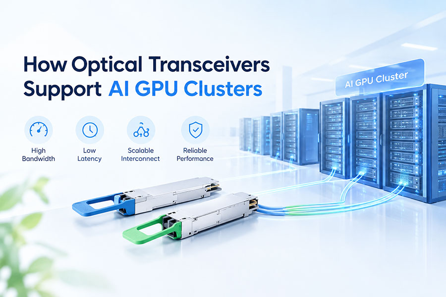
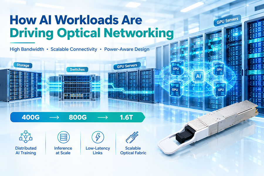
Artificial intelligence workloads require massive computing power and continuous data exchange between GPUs, servers, and network switches. As AI models become larger and training clusters expand, network bandwidth, latency, congestion, and power consumption have become important factors affecting overall system performance.
Optical transceivers help address these challenges by converting electrical data signals into optical signals for transmission through fiber optic cables. They enable high-bandwidth connections between GPU servers, network adapters, and fabric switches, supporting scalable AI infrastructure across racks and data center halls.
From 400G and 800G optical modules to emerging 1.6T connectivity solutions, optical technology is becoming increasingly important for next-generation AI data centers. However, its role depends on the network architecture. Optical transceivers are commonly used in scale-out networks connecting servers and switches, while GPU-to-GPU scale-up communication may use different technologies, including dedicated high-speed interconnects and co-packaged optical solutions.
1. Why AI GPU Clusters Need High-Speed Optical Connectivity
An AI GPU cluster combines multiple GPUs, servers, high-speed network adapters, switches, and storage systems to perform large-scale training and inference tasks. These components must exchange model parameters, activations, gradients, datasets, and intermediate results efficiently.
During distributed training, GPUs frequently exchange data through collective communication operations such as All-Reduce. If the network cannot deliver sufficient bandwidth or experiences excessive congestion, GPUs may spend more time waiting for data instead of performing computations.
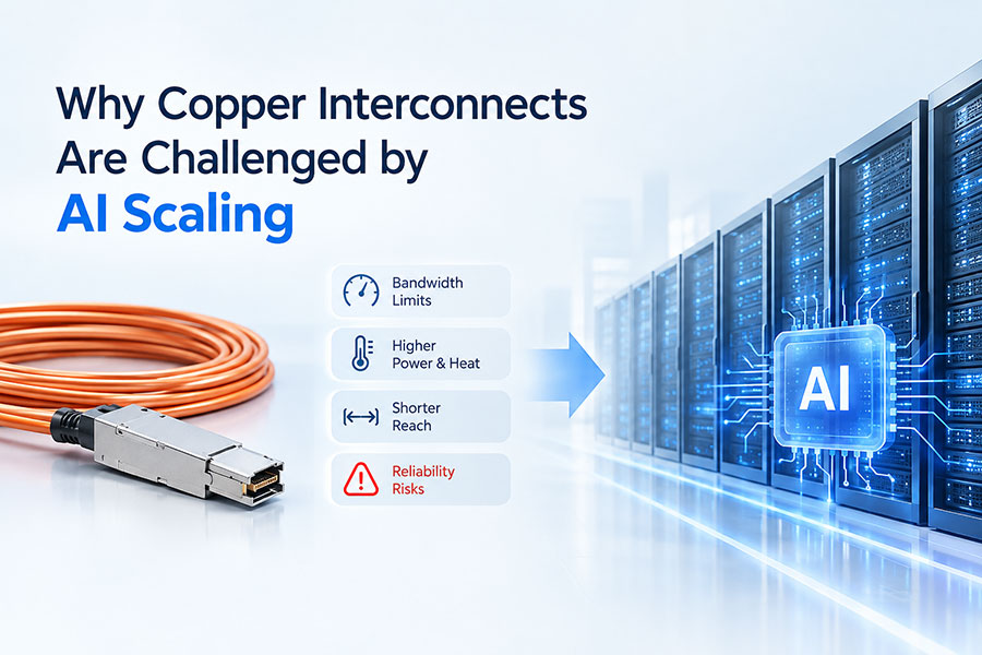
Optical transceivers provide the physical connectivity required to distribute high-speed traffic across a large cluster. They help network architects build links that extend beyond the practical reach of many direct electrical connections while supporting high port density and flexible fiber infrastructure.
The main requirements include:
High bandwidth for distributed training and large data transfers
Reliable communication between GPU servers and fabric switches
Predictable network performance under heavy traffic
Efficient power consumption and thermal management
Scalable connectivity as GPU counts and cluster sizes increase
2. What Is an Optical Transceiver in an AI Data Center?
An optical transceiver is a networking component that integrates optical transmission and reception functions in a common module. The transmitter converts electrical data into optical signals, while the receiver converts incoming optical signals back into electrical signals.
In an AI data center, an optical transceiver is commonly installed in a supported port on a network switch or network adapter. It connects to another compatible optical interface through fiber cabling, allowing data to travel between devices in the cluster.
A typical optical link includes:
GPU servers or computing nodes that generate and consume data.
Network interface cards or high-speed network adapters.
Ethernet or InfiniBand switches that forward traffic through the cluster.
Optical transceivers that provide electrical-to-optical and optical-to-electrical conversion.
Fiber optic cables, connectors, patch panels, and other passive components.
The exact arrangement depends on the cluster architecture. Some deployments use pluggable transceivers with separate fiber cabling, while others may use active optical cables or more highly integrated optical engines.
3. Understanding Scale-Up and Scale-Out Networks
AI networking is commonly divided into scale-up and scale-out communication, although the precise boundary depends on the system architecture.
Scale-up networking connects processors and accelerators within a tightly integrated computing domain. It emphasizes high-bandwidth, low-latency communication between GPUs and other components. Technologies such as NVLink and dedicated accelerator interconnects are common examples.
Scale-out networking connects multiple servers and computing nodes through a larger network fabric. It allows an AI workload to use GPUs distributed across racks and servers rather than relying on a single computing system.
Optical transceivers are especially important in scale-out networks because fiber links allow high-speed connectivity across longer physical distances. Optical technologies may also be incorporated into scale-up architectures through integrated photonics or co-packaged optics, depending on the implementation.
| Characteristic | Scale-Up Network | Scale-Out Network |
|---|---|---|
| Primary Purpose | Connect GPUs and accelerators within a tightly integrated computing domain | Connect servers and computing nodes across the cluster |
| Common Technologies | Dedicated GPU interconnects and high-speed local links | InfiniBand or high-performance Ethernet |
| Typical Physical Environment | Within a system, tray, or rack-scale platform | Across servers, racks, rows, or data center areas |
| Role of Optical Connectivity | Depends on system architecture; integrated optical technologies are an option | Pluggable optical transceivers and fiber links are widely used |
| Main Design Priorities | High bandwidth and tightly coupled communication | Bandwidth, congestion management, scalability, and reach |
4. How Optical Transceivers Improve GPU Cluster Communication
Optical transceivers provide a high-speed physical connection between network devices. After a server generates network traffic, its network adapter sends electrical signals to the optical transmitter. The transceiver converts the signals into light for transmission through fiber.
At the receiving end, another compatible transceiver converts the optical signals back into electrical signals for processing by the destination network interface or switch.
This process supports high-bandwidth connections between GPU servers and the switches that form the AI fabric. By providing longer-reach links than many direct electrical connections, fiber can help connect equipment across racks and other data center spaces without requiring every device to be located next to its network counterpart.
Optical transceivers do not automatically make every network operation faster. Actual performance depends on the transceiver design, link distance, switch latency, congestion, protocol configuration, and network topology. Their primary contribution is enabling the physical bandwidth, reach, and connectivity needed by large AI clusters.
5. Why Distributed AI Training Requires High Bandwidth
Distributed AI training splits computation across many GPUs. Each GPU processes part of the workload, and the computing nodes exchange intermediate data to keep the overall training process synchronized.
Collective communication operations such as All-Reduce can generate substantial traffic between GPUs distributed across multiple servers. When communication becomes a bottleneck, GPUs may wait for data or synchronization rather than continuously executing computations.
High-speed optical links help provide the capacity required for these data exchanges. Network architects must also consider congestion control, routing, packet loss, traffic patterns, and the relationship between the compute fabric and the available network bandwidth.
For large-scale clusters, bandwidth must be evaluated across the complete network rather than at the level of an individual optical port. The number of links, switch capacity, network topology, and oversubscription ratio all affect the performance that the GPUs can actually achieve.
6. 400G, 800G, and 1.6T Optical Transceivers for AI
As GPU clusters expand, optical interconnects are moving toward higher aggregate data rates. 400G and 800G transceivers support existing high-speed AI data center deployments, while 1.6T solutions are advancing the next generation of network connectivity.
Higher data rates can provide greater capacity per port, potentially reducing the number of ports and physical connections required for a given bandwidth target. However, the benefits depend on how the modules are integrated into the switches, adapters, and network fabric.
| Optical Generation | Aggregate Data Rate | Typical Role | Selection Consideration |
|---|---|---|---|
| 400G | 400Gbps | High-speed Ethernet and InfiniBand cluster connections where supported | Optical lane architecture, reach, and host interface |
| 800G | 800Gbps | Higher-bandwidth AI fabrics and hyperscale data center networks | Port density, module power, cooling, and switch support |
| 1.6T | 1.6Tbps | Next-generation high-bandwidth AI and data center interconnects | Platform maturity, electrical interface, optical architecture, and power efficiency |
These aggregate rates describe the nominal capacity of the optical interface, not guaranteed application throughput. Actual performance is affected by protocol overhead, the number of parallel links, network utilization, congestion, and the capabilities of the attached devices.
7. Optical Lane Architecture and PAM4 Modulation
High-speed optical modules commonly combine multiple optical lanes to achieve their total data rate. Each lane carries part of the aggregate traffic, and the host electrical interface must be compatible with the module's lane configuration.
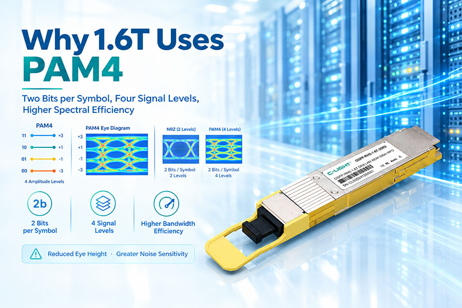
PAM4 modulation uses four signal levels to encode two bits per symbol. Compared with NRZ, which uses two signal levels and one bit per symbol, PAM4 can transmit more bits per symbol at a given symbol rate. It also introduces stricter signal-quality requirements, making transmitter linearity, receiver performance, DSP, and error correction important considerations.
For example, some 400G modules use four 100G-class optical lanes, while some 800G designs use eight 100G-class lanes or other supported lane configurations. The exact implementation depends on the product and standard.
When evaluating a module, verify its aggregate speed, electrical lane count, optical lane count, modulation format, and supported host interface. The nominal data rate alone does not describe the complete optical architecture.
8. Choosing SR, DR, FR, and LR Optical Transceivers
Optical reach categories help identify the intended link distance and fiber architecture. The correct category depends on the network layout, cable route, fiber type, connector arrangement, and required optical budget.
| Optical Category | Typical Fiber | General Application |
|---|---|---|
| SR | Multimode fiber | Short-reach connections within data centers |
| DR | Single-mode fiber | Data center links using supported single-mode parallel optics |
| FR | Single-mode fiber | Many 2 km-class data center links |
| LR | Single-mode fiber | Commonly 10 km-class single-mode connectivity |
For example, an 800G SR8 transceiver may use 850 nm VCSEL arrays with multimode fiber for short-reach links, while an 800G single-mode design may use a different optical lane arrangement and wavelength architecture.
Reach labels are not universal guarantees across all module generations. Check the product datasheet for the supported fiber grade, transmission distance, connector type, optical power specifications, and applicable protocol.
9. Multimode vs Single-Mode Fiber for GPU Clusters
Multimode and single-mode fiber serve different optical link requirements. Multimode fiber is commonly used for short-reach data center connections, while single-mode fiber supports a broad range of distances and is widely used in high-speed optical networking.
Multimode links frequently use 850 nm VCSEL-based transceivers. These can provide cost-effective connectivity for suitable short-reach configurations.
Single-mode links commonly use 1310 nm-class optics and support many DR, FR, and LR applications. Depending on the module architecture, single-mode technologies may include DFB lasers, EML transmitters, silicon photonics, and other integrated optical designs.
| Characteristic | Multimode Fiber | Single-Mode Fiber |
|---|---|---|
| Typical Wavelength | 850 nm for many SR links | 1310 nm and other wavelengths, depending on design |
| Common Laser Technology | VCSEL | DFB, EML, silicon photonics-based implementations, and others |
| Typical Use | Short-reach data center links | Short-, medium-, and longer-reach applications |
| Deployment Consideration | Distance limits and installed multimode fiber grade | Optical budget, connector loss, and link architecture |
| Upgrade Planning | Evaluate the supported reach at the target data rate | Evaluate current and future reach requirements |
The correct fiber type should be selected according to the module specification and actual cable route. Fiber type, wavelength, connector, and reach must be considered together rather than as independent choices.
10. InfiniBand vs Ethernet for AI GPU Clusters
InfiniBand and Ethernet are both used to build high-performance networks for AI and accelerated computing. The correct choice depends on the software environment, network architecture, performance requirements, operational preferences, and supported hardware.
InfiniBand is commonly used in tightly integrated high-performance computing and AI environments. Ethernet-based AI fabrics may use technologies such as RoCEv2, along with appropriate loss management, congestion control, routing, and network configuration.
Optical transceivers provide the physical optical connectivity in either architecture when the network design uses pluggable optical links. However, a transceiver must explicitly support the intended application and compatible host interface.
| Characteristic | InfiniBand | Ethernet with RoCEv2 |
|---|---|---|
| Network Type | High-performance networking fabric | Ethernet fabric with RDMA over Converged Ethernet |
| Common Applications | AI training, HPC, and distributed computing | AI clusters, cloud data centers, and enterprise infrastructure |
| Optical Connectivity | Uses compatible optical transceivers and cables | Uses compatible Ethernet optical transceivers and cables |
| Design Priorities | Low latency, bandwidth, routing, and fabric performance | Bandwidth, congestion management, interoperability, and operations |
| Compatibility | Requires support for the relevant InfiniBand generation | Requires support for the relevant Ethernet speed and optical specification |
InfiniBand and Ethernet optical modules should not be assumed interchangeable merely because they share an aggregate data rate or form factor. Verify protocol support and the requirements of the host equipment before deployment.
11. Low Latency and Network Performance
AI training performance depends on more than maximum bandwidth. Network latency, congestion, packet loss, communication synchronization, and the behavior of collective operations can all affect the time required to complete a workload.
Optical transceivers enable high-speed physical links, but they do not eliminate switching delays or congestion. The complete network must be designed to deliver predictable performance under the traffic patterns generated by distributed training and inference.
Important design considerations include:
Choosing supported high-bandwidth optical links for the expected traffic load
Minimizing unnecessary network hops where practical
Designing adequate switch and inter-switch capacity
Configuring routing and congestion management appropriately
Maintaining optical signal quality and controlling link errors
Fiber propagation delay also depends on physical distance. The fastest design is not necessarily the one with the highest transceiver data rate; overall performance depends on the entire data path, from the network adapter through the fabric to the destination GPU server.
12. AI Network Topology and Oversubscription
The topology determines how GPU servers, network adapters, and switches are connected. Common designs include leaf-spine networks and other multi-tier or application-specific high-performance topologies.
In a leaf-spine architecture, leaf switches connect to servers, while spine switches provide paths between leaf switches. Optical transceivers and fiber cabling commonly provide the inter-switch links, particularly when the equipment is distributed across multiple racks.
Oversubscription occurs when the total potential traffic entering a part of the network exceeds the capacity available toward the next network stage. Even high-speed 800G optical links cannot compensate for an insufficiently provisioned fabric.
When planning a GPU cluster, evaluate the number of GPU servers, network ports per server, switch port counts, uplink capacity, traffic patterns, and expected growth. The optical transceiver specification should fit the resulting topology rather than being selected independently.
13. Optical Power Budget and Link Reliability
Optical power budget is important when connecting AI networking equipment through fiber links, patch panels, and other passive components. A link must provide sufficient received optical power while remaining within the receiver's specified operating range.
A simplified calculation is:
Available Optical Budget = Minimum Transmitter Output Power − Receiver Sensitivity
The estimated path loss should include fiber attenuation, connector loss, splice loss, and relevant optical penalties. The design should also include an appropriate engineering margin.
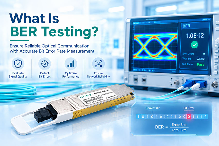
For high-speed AI networks, signal quality and error performance must be verified after installation. Poor connectors, incorrect fiber polarity, incompatible modules, excessive path loss, or incorrect lane mapping can prevent a link from operating reliably.
Optical diagnostics and link testing help confirm transmitter and receiver power levels, module operating conditions, and overall link performance. Monitoring should be combined with appropriate switch and network-adapter diagnostics.
14. Power Consumption and Thermal Management
Power efficiency is an increasingly important factor in AI data centers because a large cluster may contain thousands of optical connections. The combined power demand of these modules contributes to the electrical and cooling requirements of the networking infrastructure.
Higher-speed optical modules may require more sophisticated signal processing, transmitter and receiver circuitry, and thermal management. Actual power consumption depends on the product design, supported reach, lane architecture, optical technology, and operating conditions.
When selecting optical transceivers, verify:
Typical and maximum module power consumption
Host port power allowance
Switch airflow direction and cooling design
Operating temperature range
Thermal performance with the planned port population
Power must be considered at the system level. A module with lower individual power consumption may still require a broader network redesign if it does not provide adequate reach, density, or host compatibility for the application.
15. Optical Transceiver Reliability and Monitoring
AI clusters rely on continuous communication between computing nodes. A network link failure can interrupt data exchange and affect workload execution, cluster utilization, and operational availability.
Reliable optical connectivity depends on module quality, compatible equipment, correct installation, fiber cleanliness, adequate optical power, and thermal stability. The complete link should be evaluated rather than relying only on the transceiver's nominal data rate.
Digital Optical Monitoring (DOM) or Digital Diagnostics Monitoring (DDM), where supported, can provide information such as module temperature, supply voltage, laser bias current, transmit power, and receive power.
For large deployments, monitoring should be combined with network telemetry, link error counters, and appropriate maintenance procedures. These tools can help engineers identify abnormal operating conditions and troubleshoot faults before they cause wider service disruption.
16. Choosing Optical Transceivers for 400G and 800G AI Fabrics
When selecting 400G or 800G optics, the first step is to establish the supported network speed and architecture. Next, determine the connection type, reach, fiber grade, lane configuration, and host compatibility.
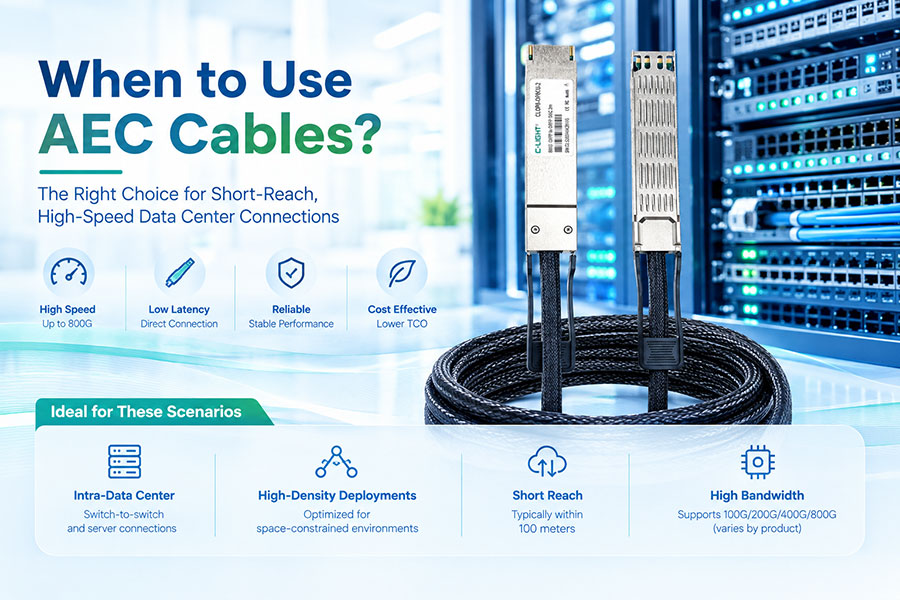
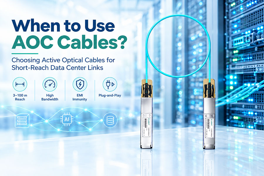
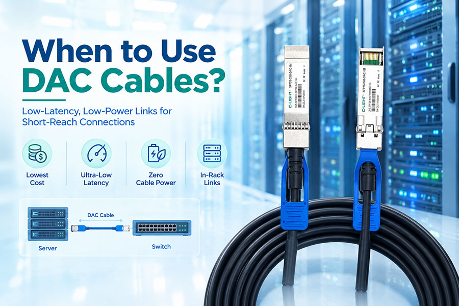
For short-reach connections, suitable SR modules, active optical cables, or direct-attach solutions may be considered. For single-mode fiber links across racks or data center areas, appropriate DR, FR, or other supported transceiver designs may be more suitable.
Compare the relevant options across the following parameters:
| Selection Parameter | What to Verify |
|---|---|
| Aggregate Data Rate | 400G or 800G support on the host platform |
| Host Interface | Supported module form factor and electrical lane configuration |
| Optical Reach | Required link length and optical standard |
| Fiber Type | Multimode or single-mode fiber and the supported grade |
| Connector | LC, MPO/MTP, or other supported optical interface |
| Power and Cooling | Module power specification and switch thermal limits |
| Interoperability | Supported protocol, remote transceiver, host firmware, and breakout options |
The final selection should be checked against product documentation and platform requirements. The same data rate can be implemented through different optical architectures, so the complete part number and specification are essential during procurement.
17. Optical Cabling, Breakout Links, and Deployment
A GPU cluster requires more than optical transceivers. Fiber cabling, connectors, patch panels, polarity, routing, and cable management all affect the quality and maintainability of the deployed network.
Some high-speed modules support breakout configurations that divide an aggregate link into multiple lower-speed connections. For example, a supported 400G configuration may provide four 100G links. Certain 800G designs also support specified breakout arrangements, depending on the module and platform.
Before installing a breakout link, confirm:
Supported breakout mode on both endpoints
Electrical and optical lane mapping
Correct fiber polarity and connector arrangement
Compatible remote-end optics
Supported host configuration and firmware
Structured cabling can improve serviceability by separating trunk infrastructure from equipment-side connections. However, every additional connector and intermediate component must be included in optical loss calculations, and the cable configuration must follow the module's requirements.
18. The Role of 1.6T Optical Transceivers and Integrated Photonics
As AI workloads continue to grow, 1.6T optical connectivity is advancing as a higher-bandwidth option for next-generation data center networks. These systems place increasing demands on electrical interfaces, optical lanes, signal processing, power consumption, and module cooling.
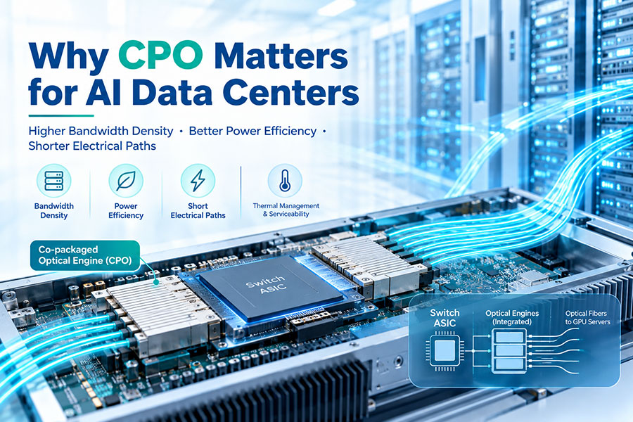
At the same time, the industry is developing more highly integrated optical technologies, including silicon photonics, Linear Pluggable Optics (LPO), Near-Packaged Optics (NPO), and Co-Packaged Optics (CPO).
These technologies address different aspects of optical integration. LPO reduces or changes the role of conventional module DSP functions in supported architectures. NPO positions optical engines closer to switching or computing ASICs, while CPO integrates optical engines more closely with the host package.
Integrated photonics can help reduce the reach and power demands of high-speed electrical connections within a system. Nevertheless, each approach introduces its own requirements for thermal design, serviceability, interoperability, and system architecture. Pluggable transceivers remain important where modular replacement, flexible deployment, and field maintenance are priorities.
19. How C-LIGHT Optical Connectivity Supports AI Networks
C-LIGHT provides optical connectivity solutions for high-speed data center networks, including optical transceivers and copper or optical cable assemblies for different link requirements.
For AI GPU cluster projects, the selection of a suitable solution depends on the intended Ethernet or InfiniBand architecture, port speed, transmission distance, cabling design, and host platform.
Relevant connectivity categories include:
400G optical transceivers for supported high-speed cluster links
800G OSFP and other platform-compatible high-speed optical solutions
Next-generation 1.6T optical connectivity solutions
DAC, AOC, and AEC interconnect products for suitable short-reach connections
Fiber cabling and high-density connectivity for data center deployment
During product selection, verify the complete optical and electrical specification, supported module coding, fiber requirements, power limits, and compatibility with the target switches and network adapters. These checks help ensure that the selected components fit the intended AI networking design.
20. How to Select Optical Transceivers for an AI GPU Cluster
The most effective selection process begins with network architecture and works downward to the physical connection. Choosing a transceiver only by aggregate bandwidth may overlook host compatibility, optical reach, fiber type, cooling, and the number of links required to support the cluster.
Use the following checklist when preparing an AI optical networking project:
| Design Item | Information to Confirm |
|---|---|
| GPU Cluster Size | Number of servers, GPUs, and network ports |
| Network Architecture | Scale-up, scale-out, topology, and oversubscription requirements |
| Network Protocol | InfiniBand or Ethernet with the intended configuration |
| Port Speed | 400G, 800G, or the supported next-generation interface |
| Physical Reach | Rack-to-rack distance and complete fiber route |
| Optical Architecture | SR, DR, FR, or other specified module type |
| Fiber Infrastructure | Fiber type, connector, polarity, and patching arrangement |
| Power and Cooling | Module power, host limits, and thermal environment |
| Compatibility | Host device, remote endpoint, firmware, and breakout support |
| Validation | Optical budget, link errors, module diagnostics, and interoperability tests |
For AI data centers, the objective is to create a balanced network in which optical links, switches, network adapters, and cabling provide the bandwidth and reliability required by the workload. Proper selection and validation help avoid physical-layer bottlenecks that could otherwise limit cluster performance.
21.Conclusion
Optical transceivers are an important part of AI GPU cluster networking because they provide high-bandwidth fiber connectivity between servers, network adapters, and fabric switches. They support the expansion of scale-out networks across racks and data center areas while offering flexibility in reach, cabling, and network design.
As the industry moves from 400G to 800G and 1.6T connectivity, module selection must account for the complete optical and electrical architecture, including lane configuration, fiber type, transmission distance, connector design, power consumption, cooling, and host compatibility.
Optical transceivers alone do not determine AI cluster performance. Network topology, congestion control, switch capacity, protocol configuration, and the communication patterns of distributed training workloads are equally important. A properly engineered optical fabric combines these elements to support scalable, reliable, and efficient AI computing infrastructure.
 >
>

 >
>
 >
>
 >
>
 >
>
 >
>
 >
>
 >
>