TEL:+86 132 6656 7067




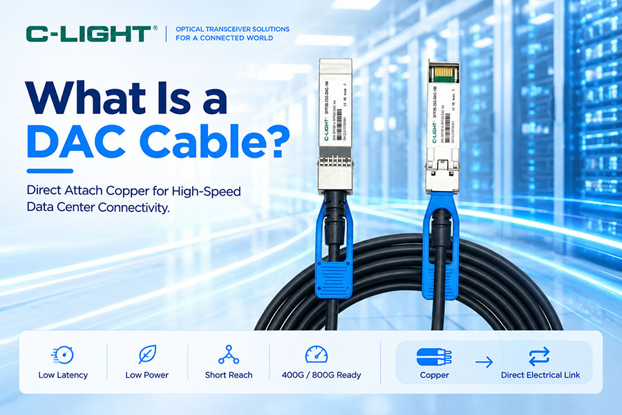
As data center networks move toward 400G, 800G, and higher-speed connectivity, short-reach interconnects must provide high bandwidth without adding unnecessary power consumption, latency, or cost. DAC (Direct Attach Copper) cable is designed for these short-distance applications by combining copper conductors with high-speed electrical connectors and, in some active implementations, signal-conditioning components. Unlike an optical transceiver and fiber link, a DAC carries the signal electrically over copper, making it particularly suitable for server-to-switch, switch-to-switch, GPU-to-switch, and other short in-rack connections in data centers and AI clusters.
1. What Is a DAC Cable?
DAC stands for Direct Attach Copper. A DAC cable is a high-speed copper interconnect with transceiver-style connectors integrated at both ends. It provides a direct electrical connection between compatible network ports without requiring separate optical transceivers and optical fiber.
DAC cables are commonly used for short-reach connections where low latency, low power consumption, high bandwidth, and deployment simplicity are important.
2. How Does a DAC Cable Work?
A DAC carries high-speed electrical signals directly between two compatible host interfaces. The cable assembly contains copper conductors, high-speed connectors, shielding and mechanical components, and may include active electronics depending on the cable type.
The simplified signal path is:
Switch / Server / GPU → High-Speed Electrical Interface → DAC Cable → High-Speed Electrical Interface → Switch / Server / GPU
3. What Are the Main Components of a DAC Cable?
A typical DAC assembly includes high-speed copper cable conductors, connector assemblies, signal-integrity structures, shielding, and mechanical components. Passive DACs mainly rely on the cable and connector design, while active DACs can include electronic components such as retimers or equalization circuits.
The exact construction depends on data rate, cable length, gauge, connector type, and electrical performance requirements.
4. What Is a Passive DAC?
A passive DAC is a direct electrical copper cable without active signal-conditioning electronics in the signal path. It relies on the transmitter and receiver interfaces to provide the required signal integrity over the specified cable length.
Because it does not require active electronics, passive DAC typically offers very low power consumption and low latency, making it suitable for short connections.
5. What Is an Active DAC?
An active DAC includes electronic components within the cable assembly to improve signal integrity and extend the practical transmission distance compared with a passive copper implementation.
Active DAC can be useful when passive copper loss becomes too high for the required data rate and cable length.
6. Passive DAC vs Active DAC
| Parameter | Passive DAC | Active DAC |
|---|---|---|
| Signal Conditioning | No active signal electronics | Includes active electronics |
| Power Consumption | Very low | Higher than passive DAC |
| Latency | Very low | Very low, application dependent |
| Reach | Shorter | Longer than passive implementations |
| Cost | Lower | Higher |
| Typical Use | Short in-rack connections | Longer short-reach connections |
7. Why Is DAC Cable Used in Data Centers?
DAC cables are well suited to data centers because many network connections occur over relatively short physical distances. A server may connect directly to a top-of-rack switch, or a GPU system may connect to a nearby high-speed switch through a short copper interconnect.
For these applications, DAC can provide a lower-cost and lower-power alternative to optical transceivers and fiber assemblies.
8. What Are the Advantages of DAC Cables?
Key advantages include low power consumption, low latency, relatively low cost, simple deployment, and compact short-reach connectivity. DAC also avoids optical conversion because the signal remains electrical throughout the cable path.
These properties make DAC attractive for high-density server racks, AI clusters, HPC systems, and short switch-to-switch connections.
9. What Are the Limitations of DAC Cables?
The main limitation is transmission distance. Copper cable loss increases as data rate and cable length increase, so DAC is generally more appropriate for short-reach applications than for long-distance interconnects.
DAC cables can also be heavier and less flexible than optical fiber assemblies at longer lengths, which can become important in high-density rack environments.
10. DAC Cable and Transmission Distance
The usable distance of a DAC depends on data rate, conductor gauge, connector design, host interface, cable construction, and whether the cable is passive or active.
In many data center applications, DAC is used for connections of a few meters. C-LIGHT's current product range includes 400G and 800G DAC configurations designed primarily for short in-rack and adjacent-equipment connections.
11. DAC Cable and Copper Gauge
Copper cable gauge affects electrical resistance, insertion loss, thermal characteristics, mechanical size, and flexibility. Higher-speed DAC products commonly use carefully selected copper gauges to balance signal integrity and cable handling requirements.
For example, C-LIGHT offers 400G and 800G DAC configurations using different cable gauges depending on the connector combination and cable length.
12. DAC Cable and PAM4
Modern high-speed DAC cables commonly carry PAM4 electrical signals. PAM4 uses four amplitude levels and carries two bits per symbol, allowing higher bit rates without requiring a proportional increase in symbol rate.
However, PAM4 also creates tighter signal-integrity requirements because the separation between adjacent signal levels is smaller.
13. DAC Cable and Signal Integrity
At high data rates, copper cable performance depends on insertion loss, return loss, impedance control, crosstalk, reflections, skew, and other signal-integrity characteristics.
As lane rates increase toward 100G and 200G per lane, the electrical channel must be carefully designed to maintain adequate eye opening and receiver margin.
14. DAC Cable and Insertion Loss
Insertion loss represents the reduction in signal amplitude caused by the transmission path. In a copper DAC, insertion loss comes from the cable conductors, connectors, PCB interfaces, and other elements in the high-speed electrical path.
Higher data rates generally place tighter limits on the amount of insertion loss the channel can tolerate.
15. DAC Cable and Return Loss
Return loss describes signal reflections caused by impedance discontinuities along the electrical path. Connectors, transitions, cable geometry, and PCB interfaces can all contribute to reflections.
Good impedance control is essential because excessive reflections can distort the waveform and reduce the available receiver margin.
16. DAC Cable and Crosstalk
Crosstalk occurs when electrical energy from one lane or channel interferes with another. High-speed multi-lane DAC cables must maintain sufficient isolation between lanes to prevent signal degradation.
Shielding, conductor geometry, connector design, and cable construction all influence crosstalk performance.
17. DAC Cable and Latency
DAC provides very low physical transmission latency because the signal travels directly through copper without optical conversion. Passive DAC is especially attractive when minimizing the additional processing path is important.
The total system latency still depends on the host devices, PHYs, retimers, switches, and other active components, so cable latency should be considered within the complete system architecture.
18. DAC Cable and Power Consumption
Passive DAC can consume very little power because there are no active components within the cable assembly. This is an important advantage in high-density data centers where the aggregate power consumption of thousands of interconnects can become significant.
Active DAC consumes more power because it contains signal-conditioning electronics, but it can provide better electrical performance over longer short-reach links.
19. DAC Cable vs AOC
AOC stands for Active Optical Cable. Unlike DAC, an AOC uses optical fibers and active optical conversion components integrated into the cable assembly.
| Parameter | DAC | AOC |
|---|---|---|
| Transmission Medium | Copper | Optical fiber |
| Signal Type | Electrical | Optical inside the cable |
| Typical Reach | Shorter | Longer |
| Power | Very low for passive DAC | Higher due to optical electronics |
| Weight | Higher at longer lengths | Lower |
| EMI Susceptibility | Higher | Very low |
| Cost | Generally lower | Generally higher |
20. DAC Cable vs Optical Transceiver
A DAC integrates the cable and connector functions into one direct-attach assembly, while an optical transceiver converts electrical data into optical signals for transmission over fiber and converts them back at the receiver.
DAC is generally preferred for short copper connections, while optical transceivers are more appropriate when longer reach, lower cable weight, EMI immunity, or flexible fiber routing is required.
21. DAC Cable vs AEC
AEC stands for Active Electrical Cable. Like DAC, an AEC uses copper conductors, but it incorporates active signal-conditioning electronics to improve electrical performance and support longer or more demanding short-reach links.
In high-speed AI networks, AEC can occupy the space between traditional passive DAC and optical interconnects when the electrical channel requires additional reach or signal conditioning.
22. DAC vs AEC vs AOC
| Feature | DAC | AEC | AOC |
|---|---|---|---|
| Medium | Copper | Copper | Optical fiber |
| Active Electronics | Passive or limited | Yes | Yes |
| Typical Reach | Shortest | Short to medium | Longer |
| Power | Lowest for passive | Moderate | Moderate |
| Latency | Very low | Very low | Low |
| EMI Immunity | Lower | Lower | High |
| Typical Application | In-rack | AI and high-speed short reach | Longer data center links |
23. DAC Cable in 400G Networking
400G DAC cables are designed to connect high-speed 400G ports over short distances. Depending on the host interface, configurations can include QSFP112, OSFP112, OSFP56, and QSFP-DD-based designs.
C-LIGHT's 400G DAC portfolio includes direct 400G configurations as well as breakout options such as 400G-to-200G, 400G-to-100G, and 400G-to-50G, allowing a single high-speed port to connect with different downstream interfaces.
24. DAC Cable in 800G Networking
800G DAC cables are designed for even higher-bandwidth short-reach interconnects. Common architectures use eight 100G-class PAM4 electrical lanes to achieve an aggregate 800Gbps interface.
C-LIGHT currently offers 800G DAC configurations including QSFP-DD, OSFP112, and breakout architectures for high-density data center and AI cluster connectivity.
25. 400G DAC Cable Applications
400G DAC cables are commonly used for GPU-to-switch links, server-to-switch connections, switch-to-switch links, HPC systems, AI clusters, and short-distance data center interconnects.
Breakout DACs are particularly useful when one 400G port must connect to multiple lower-speed ports or when a network architecture uses different interface generations.
26. 800G DAC Cable Applications
800G DAC cables are increasingly relevant to AI and HPC environments where high-bandwidth switch ports connect directly to GPU servers, accelerator systems, or adjacent switching equipment.
Because DAC is generally limited to short distances, it is most effective when the system architecture places the connected devices within the same rack or nearby rack positions.
27. DAC Cable for AI Data Centers
AI clusters generate large volumes of east-west traffic between GPUs, switches, storage systems, and other accelerators. Short electrical interconnects can help reduce connectivity cost and power consumption within the local cluster fabric.
DAC, AEC, and optical solutions can therefore be used together, with the appropriate technology selected according to reach, power, bandwidth, and topology requirements.
28. DAC Cable for GPU-to-Switch Connections
GPU-to-switch connectivity is one of the important applications for high-speed DAC. When GPUs and switches are physically close, a direct copper connection can provide the required bandwidth without the optical components required by a fiber-based connection.
For longer distances or more complex rack layouts, AEC or optical connectivity may provide a more practical alternative.
29. DAC Cable for InfiniBand Networks
High-speed InfiniBand networks require low-latency and high-bandwidth interconnects for GPU and HPC clusters. Copper direct-attach assemblies are widely used for short connections where the physical topology allows the required cable length.
As the network scales, copper and optical interconnects can be combined to match different distances and topology requirements.
30. DAC Cable for Ethernet Networks
DAC cables are also widely used in Ethernet environments, particularly for short server-to-switch and switch-to-switch connections. High-speed Ethernet generations increasingly use PAM4-based electrical interfaces, making cable signal integrity a critical design consideration.
31. DAC Cable Breakout Configurations
A breakout DAC splits one higher-speed interface into multiple lower-speed interfaces. This allows network architects to connect equipment operating at different port speeds without requiring separate cable assemblies for every link.
Examples include 400G-to-4x100G, 400G-to-2x200G, and other configurations depending on the connector types and supported host interfaces.
32. What Is the Difference Between DAC and Breakout DAC?
A standard DAC connects one port directly to one matching port. A breakout DAC connects one higher-speed port to multiple lower-speed ports using multiple connector ends on one cable assembly.
The exact breakout ratio depends on the lane architecture and supported interface standards.
33. DAC Cable Connector Types
DAC cables are available in a range of high-speed connector formats, including QSFP+, QSFP28, QSFP56, QSFP-DD, QSFP112, OSFP, and OSFP112, depending on the generation and data rate.
Connector selection must match the host port, electrical lane architecture, mechanical specification, and supported signaling rate.
34. DAC Cable and MSA Compatibility
High-speed DAC cables commonly follow the mechanical and electrical requirements of relevant industry specifications and multi-source agreements. Compatibility is not determined by connector shape alone because the host system must also support the cable's electrical characteristics, coding, lane mapping, and management behavior where applicable.
For this reason, DAC interoperability should be validated with the actual switch, server, NIC, GPU, or other host equipment.
35. DAC Cable and Switch Compatibility
Compatibility depends on more than the nominal data rate. Host vendor coding, EEPROM information, port behavior, electrical compliance, connector type, breakout support, and software configuration can all affect interoperability.
For multi-vendor data center environments, compatibility testing is especially important when deploying large numbers of high-speed DAC cables.
36. DAC Cable and EEPROM
Many pluggable-style DAC assemblies include identification and management information stored in EEPROM. This information can be used by the host system to identify the cable, supported characteristics, coding, and other parameters.
Correct vendor coding and host compatibility can be important for preventing unsupported-cable alerts or interoperability issues.
37. DAC Cable and Cable Length
Cable length has a direct effect on electrical loss. As length increases, insertion loss and other channel impairments generally increase, reducing the available signal margin at the receiver.
For this reason, the shortest practical DAC length is often preferred when designing high-density high-speed interconnects.
38. DAC Cable and Cable Management
High-speed copper cables can be thicker and less flexible than fiber assemblies, particularly at higher data rates and longer lengths. Rack design should therefore consider cable bend radius, connector clearance, airflow, cable weight, and port density.
Good cable management helps prevent excessive mechanical stress and maintains the intended electrical performance.
39. DAC Cable and Thermal Management
Passive DAC produces very little additional heat because it contains no active signal-processing electronics. Active DAC and AEC generate more heat because of their embedded electronics.
In high-density AI and data center racks, aggregate thermal load from large numbers of active interconnects should therefore be considered during system design.
40. How to Choose a DAC Cable?
Selection should begin with the host interface and required data rate. The next considerations are cable length, passive or active architecture, breakout requirements, connector type, lane configuration, cable gauge, operating environment, and host compatibility.
For short in-rack links where power and cost are priorities, passive DAC is often the first option to evaluate. When greater short-reach performance is needed, active DAC or AEC can be considered. For longer distances, AOC or optical transceivers may be more appropriate.
41. DAC Cable Testing
High-speed DAC validation can include insertion loss, return loss, crosstalk, eye diagram analysis, jitter, BER, lane-to-lane performance, temperature testing, connector integrity, and interoperability testing.
For PAM4-based systems, waveform quality and electrical compliance are particularly important because the reduced level spacing makes the signal more sensitive to channel impairments.
42. Common Problems With DAC Cables
Typical DAC problems include excessive cable loss, damaged connectors, incorrect coding, host incompatibility, insufficient signal margin, excessive bending, poor cable management, and unsupported breakout configurations.
At very high data rates, a cable that worked correctly at a shorter length may fail when deployed at a longer length because the additional insertion loss consumes the available channel margin.
43. How to Troubleshoot a DAC Link?
Start by checking the cable type, connector configuration, host port capability, and cable length. Verify that both endpoints support the same data rate and breakout configuration.
Next, inspect the connectors and cable routing, check host diagnostics and error counters, and verify whether the link is experiencing CRC errors, BER degradation, or signal-integrity problems. Substituting a known-good compatible cable is often an effective way to isolate a cable-related issue.
44. DAC Cable vs Optical Fiber: Which Should You Choose?
DAC is generally preferred when connected devices are physically close and the priorities are low cost, low power, low latency, and simple deployment. Optical fiber becomes more attractive when the link requires greater distance, lower cable weight, higher EMI immunity, or more flexible routing.
The decision should therefore be based on the physical topology and system requirements rather than data rate alone.
45. DAC Cable FAQ
Q1. What does DAC stand for?
Q2. What is a passive DAC?
Q3. What is the difference between DAC and AOC?
Q4. Is DAC used for 400G and 800G?
Q5. What is the difference between DAC and AEC?
Q6. How long can a DAC cable be?
46. Summary
DAC (Direct Attach Copper) cable is a practical high-speed interconnect for short-distance networking. Its direct electrical architecture provides low latency, low power consumption, and cost advantages compared with many optical solutions, making it particularly useful for server-to-switch, switch-to-switch, GPU-to-switch, AI, and HPC applications. Passive DAC is optimized for the shortest and most power-efficient connections, while active DAC and AEC can extend the practical electrical reach. As networks advance to 400G, 800G, and beyond, DAC continues to play an important role alongside AOC and optical transceiver solutions.
 >
>

 >
>
 >
>
 >
>
 >
>
 >
>
 >
>
 >
>