TEL:+86 132 6656 7067




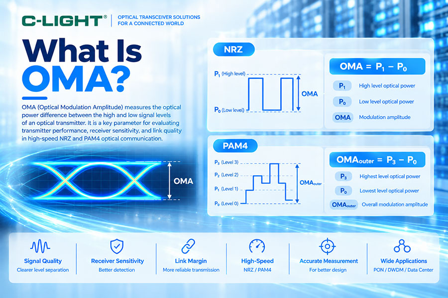
In a high-speed optical communication system, average optical power alone does not fully describe the quality of a transmitted signal. The receiver must distinguish different optical intensity levels accurately, and the separation between these levels directly affects the ability of the system to recover data. Optical Modulation Amplitude (OMA) is one of the key parameters used to characterize this signal separation. It is particularly important for high-speed NRZ and PAM4 optical transceivers, where transmitter performance, receiver sensitivity, eye opening, and overall link margin are closely related to the available optical modulation amplitude.
1. What Is OMA?
OMA stands for Optical Modulation Amplitude. It represents the optical power swing between defined signal levels of an optical transmitter.
For a conventional NRZ signal, OMA is commonly defined as the difference between the average optical power of the logical "1" level and the average optical power of the logical "0" level:
OMA = P1 − P0
where P1 is the average optical power of the high level and P0 is the average optical power of the low level.
2. Why Is OMA Important?
OMA indicates how strongly the optical transmitter modulates the optical carrier. A larger separation between signal levels generally provides the receiver with a clearer distinction between data states, while insufficient modulation amplitude can reduce the effective signal-to-noise performance and make reliable detection more difficult.
For high-speed optical links, OMA is therefore an important transmitter and system-level parameter alongside average optical power, extinction ratio, receiver sensitivity, BER, and eye quality.
3. OMA and Optical Power Levels
OMA is fundamentally a power difference, but optical power in specifications is often expressed in dBm. Because dBm is logarithmic, OMA cannot be calculated correctly by simply subtracting two dBm values.
First convert the optical powers to linear units:
P1(mW) = 10P1(dBm)/10
P0(mW) = 10P0(dBm)/10
Then:
OMA(mW) = P1(mW) − P0(mW)
The resulting OMA value can be converted back to dBm:
OMA(dBm) = 10 × log10[OMA(mW)]
4. OMA Example Calculation
Assume an NRZ transmitter has a high optical level of 0 dBm and a low optical level of -10 dBm.
0 dBm corresponds to 1 mW, while -10 dBm corresponds to 0.1 mW.
Therefore:
OMA = 1 mW − 0.1 mW = 0.9 mW
Converting 0.9 mW to dBm gives approximately -0.46 dBm.
This example demonstrates why OMA must be calculated using linear optical power rather than simply subtracting the two dBm values.
5. OMA in NRZ Optical Signals
NRZ uses two primary optical signal levels, commonly referred to as logical "1" and logical "0". The optical separation between these two levels provides a direct representation of the modulation amplitude.
Because NRZ has two signal levels, OMA can be conveniently related to the vertical opening of the optical eye. A larger eye opening generally indicates better separation between the high and low optical levels under the specified measurement conditions.
6. OMA in PAM4 Optical Signals
PAM4 uses four optical amplitude levels instead of two. This allows two bits to be represented by each symbol, increasing the data carried per symbol compared with binary NRZ.
However, four levels also create multiple eye regions and smaller vertical separation between adjacent levels. OMA analysis in PAM4 is therefore more complicated than in NRZ and must take into account the complete four-level optical waveform.
7. What Is OMAouter in PAM4?
For PAM4 transmitters, OMAouter generally refers to the optical modulation amplitude between the outermost PAM4 levels. These are the highest and lowest optical signal levels.
The concept can be expressed as:
OMAouter = P3 − P0
where P3 represents the highest PAM4 level and P0 represents the lowest level under the defined measurement conditions.
Because PAM4 has four signal levels, standards and device specifications may also define additional level-related measurements rather than relying only on OMAouter.
8. OMA and PAM4 Eye Openings
A PAM4 waveform contains three eye regions. The overall OMAouter describes the separation between the highest and lowest levels, but it does not by itself indicate whether the three individual eyes are equally open.
This is why PAM4 transmitter validation may also examine level linearity, eye height, eye width, TDECQ, transition characteristics, and other waveform-quality parameters.
9. OMA vs Average Optical Power
Average optical power describes the mean optical energy launched by the transmitter, while OMA describes the amplitude of the optical modulation.
Two transmitters can have similar average power but different OMA values. Likewise, a transmitter can provide relatively high average optical power without providing an adequately large modulation amplitude.
For high-speed system evaluation, both parameters must therefore be considered.
10. OMA vs Extinction Ratio
OMA and extinction ratio are related but are not the same parameter.
Extinction ratio is commonly defined as the ratio of the high-level optical power to the low-level optical power:
ER = P1 / P0
OMA is the difference:
OMA = P1 − P0
Therefore, extinction ratio describes the proportional relationship between signal levels, while OMA describes their absolute optical separation.
11. How Are OMA and Extinction Ratio Related?
If the high and low optical power levels are known, OMA and extinction ratio can both be calculated. Increasing the high-level power or decreasing the low-level power can change both parameters, but their numerical behavior is different because one is a difference and the other is a ratio.
This distinction becomes especially important when comparing transmitter specifications across different optical module types and data rates.
12. OMA and Receiver Sensitivity
Receiver sensitivity indicates the minimum input optical condition required to achieve the specified receiver performance. OMA, on the other hand, describes the transmitter's modulation amplitude.
In high-speed systems, receiver performance can depend on the quality of the modulated signal rather than only its total optical power. A sufficiently large OMA can improve the receiver's ability to distinguish signal levels, but sensitivity also depends on noise, bandwidth, equalization, detector performance, modulation format, and other factors.
13. OMA and Optical Link Budget
Traditional optical link-budget analysis mainly considers launch power, receiver sensitivity, and optical loss. For high-speed links, however, signal quality can become a limiting factor even when sufficient average optical power reaches the receiver.
OMA therefore complements conventional power-budget analysis. A link may have adequate average received power but still experience poor performance when the transmitter modulation amplitude, waveform quality, dispersion tolerance, or receiver response is insufficient.
14. OMA and Eye Diagram
An optical eye diagram provides a visual representation of the transmitter waveform after repeated sampling and superposition. OMA is closely related to the vertical amplitude separation visible in the eye diagram.
For NRZ, the eye consists primarily of one eye opening. For PAM4, three eye openings are present, making vertical-level balance and eye uniformity much more important.
15. How Is OMA Measured?
OMA is normally measured using an optical measurement system capable of resolving the transmitter's modulation levels. Depending on the test setup and applicable specification, an optical oscilloscope or equivalent measurement instrument can be used to capture the waveform and determine the required optical levels.
The measurement should follow the applicable standard or module specification because bandwidth, filtering, test patterns, sampling conditions, and measurement definitions can affect the reported value.
16. OMA Measurement in Optical Transceiver Testing
During transceiver qualification, OMA may be evaluated together with average optical power, extinction ratio, wavelength, spectral characteristics, eye diagram, jitter, BER, and other transmitter parameters.
For a production test environment, measurement repeatability is particularly important because small variations in laser bias, modulation current, temperature, optical coupling, and test fixtures can affect the measured result.
17. OMA and Laser Bias Current
The optical output of a directly modulated laser depends on its bias current and modulation current. The bias establishes the operating point of the laser, while the modulation component produces the optical signal variation.
Changes in these electrical operating conditions can therefore affect the resulting OMA. Excessive or insufficient drive conditions can degrade transmitter performance and may also affect eye quality and extinction ratio.
18. OMA and EML Transmitters
In EML-based optical transmitters, the laser and electro-absorption modulator work together to generate high-speed optical signals. The transmitter architecture influences optical modulation depth, extinction ratio, OMA, chirp, and other optical characteristics.
EML technology is commonly used in higher-performance optical transceivers where controlled high-speed modulation and longer-reach transmission are required.
19. OMA and VCSEL Transmitters
VCSEL-based transmitters are commonly used for short-reach multimode fiber applications. Their OMA performance is influenced by VCSEL characteristics, bias conditions, modulation current, temperature, and the electrical driver.
At high data rates, maintaining sufficient OMA while controlling power consumption and waveform distortion becomes an important transmitter-design challenge.
20. OMA in 100G Optical Transceivers
100G optical transceivers may use NRZ or PAM4 depending on the specific generation and architecture. In many 100G designs based on four 25G-class lanes, transmitter optical performance is evaluated on a per-lane basis.
The required OMA depends on the optical technology, modulation format, transmitter design, and applicable specification. Therefore, OMA values should always be interpreted together with the complete transceiver datasheet.
21. OMA in 400G Optical Transceivers
Modern 400G optical transceivers commonly use PAM4 and multiple optical lanes. In these systems, transmitter testing must account for four-level signaling, and OMAouter is only one of several parameters used to evaluate signal quality.
Other measurements may include TDECQ, eye height, eye width, level separation, jitter, extinction ratio, optical power, and BER-related performance.
22. OMA in 800G Optical Transceivers
800G optical transceivers further increase the requirements on transmitter modulation quality because they commonly use multiple high-speed PAM4 lanes. Maintaining adequate OMA and level quality across every optical lane is essential for reliable high-speed transmission.
At these data rates, optical transmitter performance must be evaluated together with electrical channel quality, DSP behavior, FEC, receiver characteristics, and system-level interoperability.
23. Why Is OMA Important in PAM4 Systems?
PAM4 increases throughput by using four amplitude levels, but the eye openings become smaller than those of a comparable binary signaling system. This makes signal-to-noise performance and level separation more sensitive.
OMA is therefore an important parameter for determining whether the transmitter produces sufficient optical amplitude for the receiver and system to distinguish the intended signal levels.
24. OMA and TDECQ
OMA and TDECQ measure different aspects of high-speed optical transmitter performance. OMA describes optical modulation amplitude, while TDECQ is a more comprehensive measure of transmitter quality for PAM4 systems that incorporates the impact of waveform distortion and noise relative to a reference receiver or signal condition.
A transmitter can have acceptable OMA but still exhibit poor TDECQ because of waveform distortion, noise, jitter, or level nonlinearity. Therefore, OMA should not be used as the sole indicator of PAM4 transmitter quality.
25. OMA and BER
Bit Error Rate (BER) represents the frequency of incorrectly received bits, while OMA represents transmitter optical modulation amplitude. A lower OMA can contribute to poor BER performance when the receiver cannot reliably distinguish the signal states, but BER is also affected by many other factors such as noise, dispersion, crosstalk, jitter, receiver performance, and FEC.
26. Factors That Affect OMA
OMA can be influenced by laser bias current, modulation current, driver output, temperature, optical coupling efficiency, laser characteristics, modulator performance, electrical signal quality, and transmitter calibration.
In a multi-lane optical module, lane-to-lane variations can also result in different OMA values across individual optical channels.
27. What Happens When OMA Is Too Low?
Insufficient OMA reduces the optical separation between signal levels. This can make the receiver more sensitive to noise and other impairments and can reduce the effective detection margin of the link.
In high-speed PAM4 systems, insufficient modulation amplitude can contribute to reduced eye openings and degraded transmitter performance.
28. Can Higher OMA Always Improve Optical Performance?
No. Increasing OMA is not an unlimited solution. Excessive modulation can increase distortion, nonlinear behavior, power consumption, or stress on the transmitter. The transmitter must operate within the specified optical and electrical conditions.
The correct design target is a balanced combination of optical power, OMA, extinction ratio, waveform quality, thermal performance, and power consumption.
29. OMA Specification in Optical Transceiver Datasheets
Optical transceiver datasheets may specify OMA using maximum, minimum, and typical values. Some specifications define OMA per lane, while PAM4 specifications may include OMAouter or other level-related parameters.
When comparing modules, the measurement definition must be checked carefully because values obtained under different test conditions may not be directly comparable.
30. OMA FAQ
Q1. What does OMA stand for?
Q2. How is OMA calculated?
Q3. What is OMAouter in PAM4?
Q4. What is the difference between OMA and extinction ratio?
Q5. Is OMA important for 400G and 800G?
Q6. Is higher OMA always better?
31. Summary
Optical Modulation Amplitude (OMA) is a fundamental parameter for evaluating the optical signal amplitude generated by a transmitter. For NRZ, it describes the optical separation between the high and low levels, while PAM4 systems introduce additional considerations such as OMAouter and multiple eye openings. OMA should be evaluated together with average optical power, extinction ratio, receiver sensitivity, eye quality, TDECQ, BER, and other system parameters. As optical transceivers move from 100G to 400G, 800G, and beyond, accurate OMA measurement and control become increasingly important for maintaining signal integrity and transmission reliability.
 >
>

 >
>
 >
>
 >
>
 >
>
 >
>
 >
>
 >
>