TEL:+86 132 6656 7067




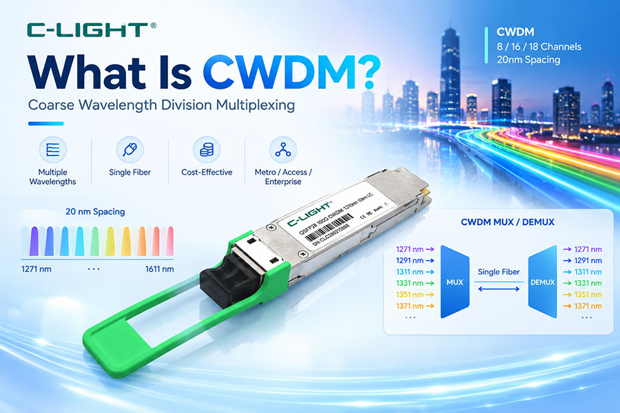
As optical networks need to carry more services without continuously deploying new fiber, wavelength division multiplexing provides a practical way to increase fiber capacity. CWDM, or Coarse Wavelength Division Multiplexing, uses multiple widely separated optical wavelengths on the same fiber. Its wide channel spacing simplifies optical component requirements+ and makes CWDM a cost-effective solution for metro networks, enterprise connectivity, access networks, and other applications where moderate capacity and transmission distance are required.
1. What Is CWDM?
CWDM stands for Coarse Wavelength Division Multiplexing. It is an optical multiplexing technology that combines multiple signals with different wavelengths onto a single optical fiber.
Each wavelength carries an independent data channel. At the receiving end, a CWDM demultiplexer separates the wavelengths back into individual optical channels.
The basic concept is:
Multiple Optical Wavelengths → CWDM MUX → Single Fiber → CWDM DEMUX → Multiple Optical Wavelengths
2. How Does CWDM Work?
CWDM assigns different wavelengths to different optical signals. Each transmitter operates at its assigned wavelength, and the CWDM multiplexer combines these signals into one fiber.
At the destination, the demultiplexer separates the individual wavelengths and sends them to the corresponding receivers.
This allows several independent data streams to share the same physical fiber without requiring a separate fiber for every service.
3. What Is the CWDM Wavelength Grid?
The ITU-T G.694.2 recommendation defines the CWDM wavelength grid with 20 nm channel spacing. The nominal wavelength range extends from 1271 nm to 1611 nm.
The wide spacing between channels is one of the defining characteristics of CWDM and allows relatively relaxed optical component requirements.
4. How Many Wavelengths Does CWDM Support?
The ITU-T CWDM grid contains 18 nominal wavelengths from 1271 nm to 1611 nm at 20 nm spacing.
| Channel | Nominal Wavelength |
|---|---|
| 1 | 1271 nm |
| 2 | 1291 nm |
| 3 | 1311 nm |
| 4 | 1331 nm |
| 5 | 1351 nm |
| 6 | 1371 nm |
| 7 | 1391 nm |
| 8 | 1411 nm |
| 9 | 1431 nm |
| 10 | 1451 nm |
| 11 | 1471 nm |
| 12 | 1491 nm |
| 13 | 1511 nm |
| 14 | 1531 nm |
| 15 | 1551 nm |
| 16 | 1571 nm |
| 17 | 1591 nm |
| 18 | 1611 nm |
Actual network equipment may use fewer wavelengths depending on the optical modules, fiber type, transmission distance, and application requirements.
5. Why Does CWDM Use 20 nm Spacing?
The relatively large 20 nm spacing provides greater tolerance for laser wavelength variation and temperature-related wavelength drift. It also allows simpler and less demanding optical filters and multiplexers.
This is an important reason why CWDM systems can use cost-effective optical components and, in many implementations, uncooled lasers.
6. CWDM Optical Transceivers
A CWDM optical transceiver is designed to operate at a specific CWDM wavelength. Common CWDM transceiver formats include SFP, SFP+, XFP, SFP28, QSFP and other form factors depending on the required data rate.
Different transceivers can operate at different wavelengths while sharing the same fiber through a CWDM MUX/DEMUX system.
7. CWDM SFP and SFP+
CWDM SFP and SFP+ modules are commonly used for Ethernet, storage, enterprise networks, and metro connectivity.
| Module | Typical Data Rate | Typical Role |
|---|---|---|
| CWDM SFP | 1G-class | Ethernet and access networks |
| CWDM SFP+ | 10G-class | Enterprise and metro networks |
| CWDM SFP28 | 25G-class | Higher-speed data connectivity |
| CWDM QSFP | 40G-class | Data center and metro applications |
8. CWDM MUX and DEMUX
A CWDM MUX combines multiple optical wavelengths into one fiber, while a CWDM DEMUX performs the reverse operation.
In many network deployments, the two functions are provided as a matched MUX/DEMUX pair at opposite ends of the optical link.
The MUX/DEMUX device is a passive optical component in many CWDM architectures and does not need to perform electrical signal regeneration.
9. CWDM Optical Fiber
CWDM systems generally use single-mode fiber because the wavelengths are intended for transmission over metro, access, and other longer optical links.
Fiber attenuation varies with wavelength, so the selected CWDM channels and actual fiber type should be considered when designing a complete link.
10. CWDM Transmission Distance
CWDM does not have one universal transmission distance. The achievable reach depends on the optical module, wavelength, fiber attenuation, MUX/DEMUX insertion loss, connectors, splices, and available optical link budget.
Common CWDM deployments range from relatively short metro links to tens of kilometers. Some specific CWDM implementations can reach longer distances under suitable optical conditions.
11. CWDM Link Budget
Link budget is an important factor when designing a CWDM network. The available optical margin must account for fiber attenuation, connector loss, splice loss, MUX/DEMUX insertion loss, and other optical penalties.
A simplified relationship is:
Available Margin = Transmitter Launch Power − Total Link Loss − Receiver Sensitivity Requirement
The actual calculation should use the specifications of the selected CWDM transceivers and passive optical components.
12. CWDM Advantages
Multiple wavelengths share one optical fiber
20 nm channel spacing simplifies optical design
Lower component complexity than dense WDM systems
Supports cost-effective optical networking
Can use uncooled laser technology in suitable designs
Suitable for metro and access applications
Provides an efficient way to expand fiber capacity
13. CWDM Limitations
Fewer channels than typical DWDM systems
Lower overall wavelength density
Limited scalability for very high-capacity long-haul networks
Transmission distance depends strongly on optical link budget
Some wavelengths can experience higher fiber attenuation
Optical amplification options are more limited than in conventional C-band DWDM systems
14. CWDM vs DWDM
| Feature | CWDM | DWDM |
|---|---|---|
| Channel Spacing | 20 nm | Typically much narrower, such as 100/50/25 GHz |
| Channel Density | Lower | Higher |
| Optical Components | Relatively simple | More complex |
| Laser Cooling | Often uncooled | More demanding wavelength control |
| Cost | Generally lower | Generally higher |
| Typical Application | Access, enterprise, metro | Long-haul, DCI, high-capacity transport |
15. CWDM vs DWDM Channel Capacity
The large difference in channel spacing means that DWDM can place significantly more wavelengths into a given optical spectrum than CWDM.
CWDM prioritizes simplicity and cost efficiency, while DWDM prioritizes wavelength density and overall fiber capacity.
This makes the two technologies complementary rather than direct replacements in every network scenario.
16. CWDM vs DWDM Wavelength Range
CWDM uses a broad wavelength grid extending from approximately 1271 nm to 1611 nm under the ITU-T G.694.2 grid.
DWDM systems commonly concentrate many closely spaced channels within optical transmission bands such as the C-band, allowing significantly greater wavelength density and making technologies such as optical amplification more practical.
17. CWDM and Optical Amplification
The broad wavelength range of CWDM creates challenges for using a single conventional optical amplifier across all CWDM channels. As a result, CWDM is commonly deployed without the same type of optical amplification architecture used in high-capacity DWDM transport systems.
For longer-distance and higher-capacity applications where optical amplification is important, DWDM is often a more suitable architecture.
18. CWDM and Passive Optical Components
CWDM networks rely heavily on passive optical components such as MUX/DEMUX devices, filters, couplers, and optical patching equipment.
Because the wavelengths are widely separated, the optical filtering requirements are generally less demanding than those of dense wavelength systems.
19. CWDM Applications
| Application | CWDM Role |
|---|---|
| Metro Networks | Multiple services over existing fiber |
| Enterprise Networks | Network capacity expansion |
| Access Networks | Multi-wavelength optical connectivity |
| Data Center Interconnect | Short and medium optical links |
| Telecom Networks | Cost-effective wavelength multiplexing |
| Campus Networks | Fiber utilization improvement |
20. CWDM in Metro Networks
CWDM is well suited to metro networks where several optical services need to share existing fiber but the network does not require the extremely high wavelength density of DWDM.
Its relatively simple optical architecture can reduce deployment cost while providing a significant increase in fiber utilization.
21. CWDM in Enterprise Networks
Enterprise networks can use CWDM to transport multiple services or connections over limited fiber infrastructure.
Different wavelengths can be assigned to different services, switches, or network segments, allowing organizations to increase capacity without installing additional fiber for every connection.
22. CWDM in Data Center Networks
CWDM can be used for selected data center and data center interconnect applications where the required reach and capacity are compatible with CWDM optical characteristics.
For very high-density 400G, 800G, and future 1.6T interconnects, other optical architectures may provide better scalability depending on reach and network design.
23. CWDM and 100G Optical Transceivers
CWDM technology can be implemented in 100G optical networking through wavelength-based transceiver architectures. For example, 100G CWDM4 uses multiple wavelengths around the 1310 nm region rather than the full 20 nm CWDM grid as separate long-distance channels.
This distinction is important: the term CWDM can describe the underlying wavelength multiplexing concept, while a specific 100G CWDM4 module has its own standardized optical architecture and wavelength specifications.
24. CWDM and CWDM4
| Feature | CWDM | CWDM4 |
|---|---|---|
| Concept | General coarse WDM technology | Specific 4-wavelength optical architecture |
| Typical Wavelengths | Broad CWDM grid | Four wavelengths around 1310 nm |
| Application | Metro, access, enterprise | 100G data center connectivity |
| Channel Count | Multiple CWDM wavelengths | 4 optical lanes |
25. CWDM and Single-Mode Fiber
CWDM optical modules normally operate over single-mode fiber. The fiber carries several wavelengths simultaneously, with each wavelength representing an independent optical channel.
When designing a CWDM link, the fiber type, wavelength-dependent attenuation, connector quality, and total optical loss should all be considered.
26. CWDM and Optical Module Wavelengths
CWDM optical transceivers are normally identified by their operating wavelength. For example, modules may be specified around 1271 nm, 1291 nm, 1311 nm, 1331 nm, 1471 nm, 1491 nm, or other wavelengths within the CWDM grid.
The transceiver wavelength must match the appropriate MUX/DEMUX channel.
27. How to Choose a CWDM Optical Module
Several parameters should be checked before selecting a CWDM transceiver:
Data rate
Operating wavelength
Transmission distance
Fiber type
Connector type
Transmitter optical power
Receiver sensitivity
Operating temperature
Form factor
Optical link budget
28. CWDM Network Design Considerations
A practical CWDM deployment should consider more than the optical module itself. The MUX/DEMUX insertion loss, fiber attenuation, connector loss, splice loss, wavelength selection, optical power margin, and equipment compatibility all affect the final link performance.
For longer links, the complete optical budget should be calculated before deployment rather than selecting the module only according to its advertised maximum distance.
29. CWDM and Network Scalability
CWDM provides a relatively simple way to increase capacity on existing fiber, but its scalability is limited by the available wavelength grid and optical power budget.
When network traffic continues to increase and the available CWDM wavelengths are insufficient, operators may migrate toward DWDM or other higher-density optical architectures.
30. CWDM Market Position
CWDM remains relevant because not every optical network requires the channel density, optical amplification, or system complexity associated with DWDM.
For access, enterprise, metro, and selected data center applications, the balance between capacity, cost, optical complexity, and deployment flexibility can make CWDM an effective solution.
31. CWDM vs Other WDM Technologies
| Technology | Channel Density | Complexity | Typical Position |
|---|---|---|---|
| CWDM | Low to moderate | Low | Access and metro |
| DWDM | High | High | Transport and DCI |
| LAN-WDM | Few closely spaced wavelengths | Moderate | High-speed Ethernet |
| BiDi | Two wavelengths | Low | Single-fiber links |
32. Future of CWDM
CWDM will continue to serve applications where simple wavelength multiplexing and cost efficiency are more important than maximum channel density.
At the same time, higher-speed data center networks are increasingly adopting 400G, 800G, 1.6T, coherent, silicon photonics, and other advanced optical technologies. As a result, CWDM will remain particularly relevant in access, metro, enterprise, and selected short- to medium-reach applications.
33. Conclusion
CWDM is a wavelength division multiplexing technology that combines multiple optical channels onto a single fiber using widely spaced wavelengths. The ITU-T G.694.2 grid uses 20 nm channel spacing, providing greater wavelength tolerance and simpler optical component requirements than dense WDM systems.
Its relatively low complexity and cost make CWDM suitable for metro, access, enterprise, and selected data center applications. When higher channel density, longer reach, or large-scale optical amplification is required, DWDM generally provides greater scalability.
 >
>

 >
>
 >
>
 >
>
 >
>
 >
>
 >
>
 >
>