TEL:+86 132 6656 7067




In a digital optical communication system, receiving a signal is not enough to determine whether a link is operating correctly. The receiver must recover the transmitted data accurately, and even a small number of incorrect bits can affect network reliability as data rates increase. Bit Error Rate (BER) is one of the most important measurements used to quantify this performance. It provides a direct way to evaluate how often transmitted bits are incorrectly detected and is widely used in optical transceiver qualification, high-speed Ethernet testing, PAM4 validation, FEC analysis, and optical link troubleshooting.
1. What Is BER?
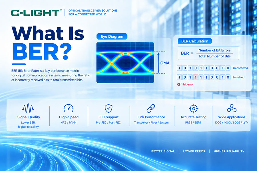
BER stands for Bit Error Rate. It is the ratio of incorrectly received bits to the total number of transmitted or received bits during a defined measurement period.
The basic formula is:
BER = Number of Bit Errors / Total Number of Transmitted Bits
For example, if a receiver detects 10 incorrect bits during the transmission of 1,000,000,000 bits, the measured BER is 1 × 10⁻⁸.
BER is normally expressed as a dimensionless ratio rather than a percentage because high-speed optical systems often target extremely low error rates.
2. Why Is BER Important in Optical Communication?
BER provides a direct indication of the accuracy of digital data transmission. A lower BER means that fewer transmitted bits are incorrectly detected by the receiver.
In optical communication, BER can be affected by optical power, receiver sensitivity, fiber attenuation, chromatic dispersion, modal effects, noise, jitter, crosstalk, reflections, transmitter quality, electrical signal integrity, and other impairments.
For high-speed optical links, BER is therefore an important system-level metric rather than simply a measurement of the optical transmitter or receiver alone.
3. How Is BER Calculated?
BER is calculated by comparing the transmitted data pattern with the data recovered by the receiver.
If a test transmits 1012 bits and the receiver detects 100 incorrect bits:
BER = 100 / 1012 = 1 × 10⁻¹⁰
The measurement accuracy depends on the number of bits tested. A short test duration cannot provide the same statistical confidence as a long-duration test involving a very large number of bits.
4. What Does a BER of 10-12 Mean?
A BER of 10-12 means that the measured error rate is one incorrect bit per 1012 transmitted bits on average under the defined test conditions.
It does not mean that an error must occur exactly once every 1012 bits. BER is a statistical measurement, so the actual occurrence of errors is probabilistic.
5. BER vs Bit Error Count
Bit error count is the number of incorrectly detected bits during a test, while BER normalizes that error count by the total number of tested bits.
For example, two tests may both detect 10 errors, but if one test transmitted 109 bits and the other transmitted 1012 bits, their BER values are significantly different.
6. BER Testing in Optical Transceivers
BER testing is commonly used during optical transceiver development, qualification, production testing, interoperability testing, and troubleshooting.
A typical test connects the transmitter under test to a compatible receiver or test instrument and sends a known pseudo-random data pattern. The receiver compares the recovered pattern with the expected sequence and counts errors.
Depending on the transceiver generation, testing may be performed at 10G, 25G, 50G, 100G, 200G, 400G, 800G, or higher aggregate data rates.
7. What Is a BER Tester?
A Bit Error Rate Tester (BERT) is a test instrument designed to generate known digital patterns, transmit them through the device or communication link under test, recover the received data, and compare the transmitted and received sequences.
A typical BERT can provide parameters such as bit rate, test pattern, error count, BER, test duration, and synchronization status.
8. What Is a PRBS Pattern?
PRBS stands for Pseudo-Random Binary Sequence. It is a deterministic digital test pattern designed to have statistical characteristics similar to random data while remaining completely known to the test system.
PRBS patterns are widely used for evaluating high-speed electrical and optical communication channels because they can stress the transmission system across a broad range of signal transitions.
9. What Is PRBS31?
PRBS31 is a pseudo-random binary sequence generated using a polynomial associated with a 31-bit shift-register sequence. It produces a very long repeating pattern and is commonly used for high-speed communication testing.
Because PRBS31 contains a long sequence before repetition, it provides a demanding test pattern for evaluating channel quality, equalization, transmitter performance, receiver performance, and BER.
10. Why Is PRBS31 Commonly Used for High-Speed Testing?
High-speed channels are affected by frequency-dependent loss, reflections, crosstalk, inter-symbol interference, and other signal-integrity limitations. A long pseudo-random sequence can exercise the channel over many combinations of transitions and consecutive bits.
For this reason, PRBS31 is often used during optical transceiver and high-speed electrical interface validation, although the exact test pattern depends on the applicable standard and test requirement.
11. What Is Pre-FEC BER?
Pre-FEC BER is the bit error rate measured before Forward Error Correction is applied. It represents the raw error condition of the received data before the FEC mechanism corrects detectable errors.
Pre-FEC BER is particularly important in modern high-speed optical systems because a link may have a measurable raw error rate while still providing an extremely low error rate after FEC processing.
12. What Is Post-FEC BER?
Post-FEC BER represents the residual error performance after Forward Error Correction has processed the received data.
A system can therefore have a relatively higher pre-FEC BER while maintaining a very low post-FEC BER if the FEC mechanism has sufficient correction capability and the incoming error distribution remains within its operating range.
13. Pre-FEC BER vs Post-FEC BER
| Parameter | Pre-FEC BER | Post-FEC BER |
|---|---|---|
| Measurement Position | Before FEC correction | After FEC correction |
| Purpose | Evaluate raw link quality | Evaluate residual error performance |
| Typical Use | Transceiver and channel validation | System reliability evaluation |
| FEC Influence | Not corrected | Corrected by FEC |
The two measurements should not be treated as interchangeable. A specification must clearly state whether the reported BER is measured before or after FEC.
14. What Is FEC?
FEC stands for Forward Error Correction. It adds redundant information to transmitted data so that the receiver can detect and correct certain transmission errors without requiring retransmission.
FEC is particularly important in high-speed Ethernet and optical communication because increasing data rates make the system more sensitive to channel impairments.
15. How Does FEC Affect BER?
FEC can significantly reduce the residual error rate seen by higher network layers. The receiver first processes the incoming data and uses the redundant coding information to identify and correct errors within the capability of the FEC scheme.
However, FEC does not make an arbitrarily poor link reliable. If the incoming error rate exceeds the correction capability or if the errors have an unfavorable distribution, the FEC decoder may fail to recover the original data.
16. BER and FEC Threshold
A FEC threshold defines the range of incoming errors within which a particular FEC implementation can maintain the required output performance.
The exact threshold depends on the FEC algorithm, code structure, implementation, error characteristics, and applicable standard. Therefore, there is no single universal FEC BER threshold that applies to every optical transceiver.
17. BER in NRZ Systems
NRZ represents data using two primary signal levels. The receiver determines whether the incoming signal corresponds to the high or low state.
Factors such as noise, insufficient eye opening, timing uncertainty, optical power degradation, and inter-symbol interference can cause the receiver to make incorrect decisions and increase BER.
18. BER in PAM4 Systems
PAM4 uses four amplitude levels and carries two bits per symbol. Although this increases data efficiency, the vertical separation between adjacent levels is smaller than in a comparable binary signaling system.
As a result, PAM4 systems are more sensitive to noise, nonlinear distortion, level imbalance, jitter, crosstalk, and other impairments. BER testing is therefore particularly important for 50G-per-lane, 100G-per-lane, and 200G-per-lane optical technologies.
19. PAM4 BER and Symbol Errors
Because PAM4 contains four signal levels, a receiver first determines which of the four levels was transmitted. The resulting symbol decision is then mapped to the corresponding bits.
A symbol error can therefore result in one or more bit errors depending on the transmitted and detected levels and the coding scheme. For this reason, PAM4 testing may distinguish between symbol-level performance and bit-level BER.
20. BER and Gray Coding in PAM4
PAM4 systems commonly use Gray-coded level mapping so that adjacent signal levels differ by only one bit. This helps reduce the bit-error impact of certain adjacent-level decision errors.
However, Gray coding does not eliminate the underlying signal-integrity problem. Poor eye separation or excessive noise can still result in significant BER degradation.
21. BER and Eye Diagram
An eye diagram provides a visual representation of signal quality, while BER provides a quantitative measurement of receiver decision errors.
For NRZ, a closed or reduced eye opening generally indicates increased difficulty in distinguishing the two signal levels. For PAM4, three eye regions must be considered, and reduced vertical or horizontal openings can increase the probability of incorrect decisions.
22. BER and Jitter
Jitter represents timing variation in a digital signal. Excessive jitter can move signal transitions away from their ideal sampling positions and increase the probability of incorrect bit decisions.
At high data rates, timing margins become smaller, making jitter analysis an important part of BER investigation.
23. BER and Signal-to-Noise Ratio
Noise reduces the receiver's ability to distinguish valid signal levels. As the noise level increases relative to the signal amplitude, the probability of crossing the receiver decision threshold also increases.
This is particularly important in PAM4 systems because the separation between adjacent levels is relatively small.
24. BER and Optical Power
Insufficient received optical power can increase BER because the receiver may not have enough signal amplitude relative to its noise floor and sensitivity requirements.
However, simply increasing optical power does not guarantee lower BER. Excessive received power can cause receiver overload, while other impairments such as dispersion, jitter, crosstalk, and waveform distortion may remain unaffected.
25. BER and Optical Link Budget
Optical link budget and BER evaluate different but related aspects of link performance. Link budget determines whether sufficient optical power is available after transmission losses, while BER determines whether the recovered digital data contains errors under the test conditions.
A link can have adequate optical power and still show poor BER because signal quality has been degraded by dispersion, reflections, noise, jitter, or electrical impairments.
26. BER and Chromatic Dispersion
Chromatic dispersion causes different optical wavelengths or spectral components to propagate at different velocities through the fiber. Over longer distances, this can broaden optical pulses and increase inter-symbol interference.
As data rates increase, the available timing margin becomes smaller, making dispersion-related penalties increasingly important in long-reach optical systems.
27. BER and Insertion Loss
Insertion loss reduces the optical power reaching the receiver. Excessive loss can reduce the received signal below the required operating range and result in increased BER or link failure.
Insertion loss should therefore be evaluated together with transmitter launch power, receiver sensitivity, connector loss, fiber attenuation, splitter loss, and other optical components.
28. BER and Crosstalk
Crosstalk occurs when energy from one electrical or optical channel interferes with another channel. In multi-lane high-speed interfaces, crosstalk can reduce signal separation and increase decision errors.
For 400G, 800G, and future higher-speed interfaces, maintaining adequate channel isolation is an important part of BER performance optimization.
29. BER Testing for 100G Optical Transceivers
100G optical transceivers can use different lane architectures and modulation formats depending on the specific product generation. BER testing should therefore follow the module's electrical and optical interface configuration.
Testing may include PRBS generation, receiver error counting, optical attenuation, temperature variation, transmitter and receiver characterization, and interoperability testing.
30. BER Testing for 400G Optical Transceivers
Modern 400G optical transceivers commonly use PAM4 lanes and require more comprehensive signal-quality validation than traditional lower-speed NRZ systems.
BER testing can be combined with eye analysis, TDECQ, jitter measurements, optical power measurements, and FEC performance evaluation to determine whether the complete link meets its required operating conditions.
31. BER Testing for 800G Optical Transceivers
800G systems typically use multiple high-speed lanes, making transmitter, receiver, electrical channel, and optical channel performance closely interconnected.
Testing should evaluate each lane where required and verify aggregate system performance. Lane-to-lane variation is also important because one degraded lane can affect the overall link performance.
32. BER Testing for 1.6T Optical Systems
As optical networking moves toward 1.6T and 200G-per-lane architectures, BER validation becomes increasingly demanding. Higher baud rates reduce timing margins and increase the impact of electrical loss, crosstalk, jitter, reflections, and optical impairments.
For these systems, BER should be evaluated together with FEC behavior, transmitter quality, receiver performance, electrical channel characteristics, and system interoperability.
33. How Long Should a BER Test Run?
BER test duration depends on the target BER, required confidence level, test standard, and number of errors that must be observed or excluded.
For very low target BER values, a meaningful test may require an extremely large number of transmitted bits. At high data rates, this can require long test periods even though the link is transmitting hundreds of gigabits per second.
34. Why Can a BER Test Report Zero Errors?
Zero detected errors does not mathematically prove that the actual BER is zero. It means that no errors were observed during the tested number of bits.
For example, if a system transmits 1012 bits without detecting an error, the measured error count is zero, but the true underlying BER may still be nonzero. Statistical confidence and test duration must therefore be considered when interpreting zero-error results.
35. BER vs SER
BER measures incorrect bits, while SER stands for Symbol Error Rate and measures incorrectly detected symbols.
The distinction becomes particularly important for PAM4 because one symbol represents two bits. Symbol-level and bit-level error behavior are related but are not identical measurements.
36. BER vs Packet Error Rate
BER operates at the bit level, while Packet Error Rate evaluates whether complete packets are received correctly.
A small BER can result in a measurable packet error rate depending on packet size because a packet containing even one incorrect bit may be considered corrupted at the packet level.
37. Common Causes of High BER
High BER can result from insufficient received optical power, excessive fiber loss, connector problems, fiber bending, dispersion, excessive jitter, crosstalk, reflections, poor transmitter performance, receiver degradation, electrical channel loss, incorrect configuration, or interoperability issues.
For a high-speed optical link, troubleshooting should examine both optical and electrical domains rather than assuming that the optical module is the only possible source of errors.
38. How to Troubleshoot High BER?
The first step is to confirm the optical power at both ends of the link and compare the measured values with the transceiver specifications. The next step is to inspect connectors, fiber routing, patch cables, and passive components.
If optical parameters are normal, engineers should investigate electrical signal integrity, lane mapping, host configuration, FEC status, jitter, crosstalk, temperature, and interoperability. BER testing with a controlled test pattern can help isolate the problem from higher-layer network traffic.
39. BER and Optical Transceiver Interoperability
Two optical modules may have compatible nominal specifications but still require interoperability validation. Differences in transmitter characteristics, receiver equalization, FEC implementation, host electrical behavior, and signal-quality margins can affect the resulting BER.
This is particularly relevant for 400G, 800G, and higher-speed modules used with switches, NICs, GPUs, and other high-performance networking equipment.
40. BER Testing Best Practices
BER testing should use a controlled test environment and a defined test pattern, data rate, optical attenuation, temperature, and measurement duration. The test equipment should be properly calibrated, and the optical and electrical interfaces should match the device specification.
For high-speed PAM4 systems, BER should not be evaluated in isolation. Eye quality, TDECQ, jitter, optical power, receiver sensitivity, FEC behavior, and other relevant parameters should also be considered.
41. BER FAQ
Q1. What does BER stand for?
Q2. How is BER calculated?
Q3. What is a good BER for optical communication?
Q4. What is the difference between pre-FEC BER and post-FEC BER?
Q5. Why is BER important for PAM4?
Q6. Can zero detected errors prove that BER is zero?
42. Summary
BER is a fundamental measurement for determining the accuracy and reliability of digital optical communication. It quantifies the ratio of incorrectly detected bits and provides an essential performance metric for optical transceivers and fiber links. In modern 400G, 800G, and 1.6T systems, BER analysis must be considered together with PAM4 signal quality, optical power, receiver sensitivity, jitter, crosstalk, dispersion, FEC, and electrical channel performance. Proper BER testing provides a quantitative basis for transceiver qualification, link validation, interoperability testing, and high-speed network troubleshooting.
 >
>

 >
>
 >
>
 >
>
 >
>
 >
>
 >
>
 >
>