TEL:+86 132 6656 7067




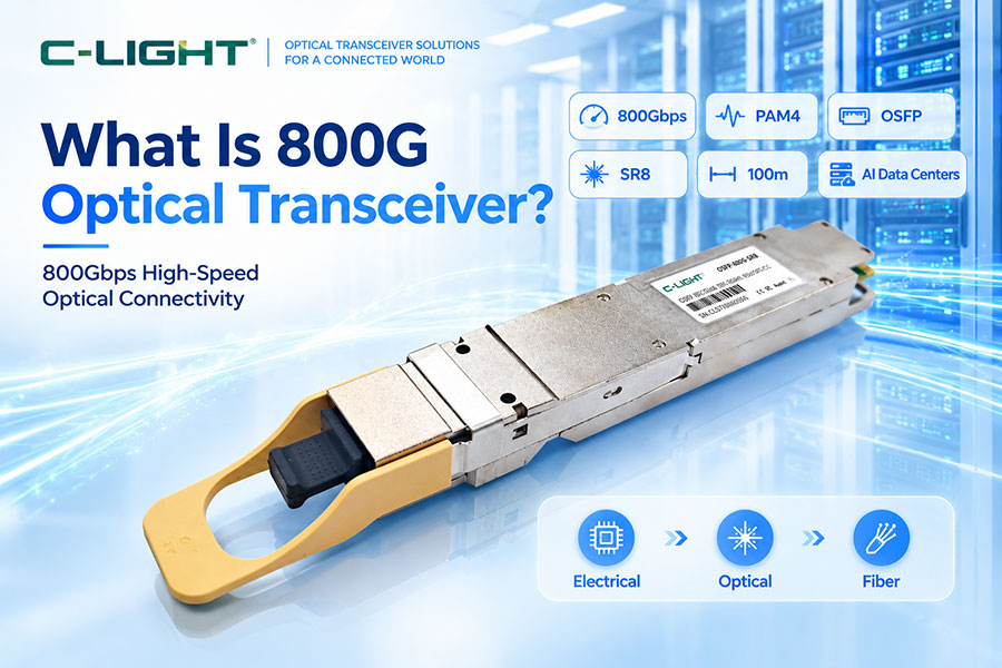
The rapid growth of AI clusters, GPU computing, hyperscale data centers, and high-performance Ethernet networks is pushing optical connectivity toward higher bandwidth per port. An 800G optical transceiver provides up to 800Gbps of aggregate optical bandwidth and is designed to move large volumes of data between switches, servers, GPUs, and other high-speed networking equipment. Depending on the required reach and network architecture, 800G modules can use OSFP or QSFP-DD packaging and different optical configurations such as SR8, DR8, 2xFR4, and longer-reach solutions. The choice of module is determined not only by data rate, but also by lane architecture, fiber type, wavelength, connector, optical budget, host compatibility, power consumption, and transmission distance.
1. What Is an 800G Optical Transceiver?
An 800G optical transceiver is a high-speed optical module designed to provide an aggregate data rate of up to 800Gbps. It converts electrical data from a switch, server, NIC, GPU system, or other host device into optical signals for transmission over fiber and converts incoming optical signals back into electrical data at the receiving side.
800G optical transceivers are mainly used where the bandwidth requirements exceed the practical capacity of 400G interfaces, particularly in AI data centers, hyperscale networks, HPC environments, and high-speed Ethernet infrastructure.
2. How Does an 800G Optical Transceiver Work?
On the transmit side, high-speed electrical signals from the host are delivered to the optical module. The module's electrical interface drives the optical transmitter, which generates and modulates the optical signal before launching it into the fiber.
On the receive side, photodetectors convert the incoming optical signal into an electrical signal. The receiver circuitry then conditions the signal before delivering it to the host electrical interface.
A simplified path is:
Host ASIC → Electrical Interface → Optical Transmitter → Fiber → Optical Receiver → Electrical Interface → Host ASIC
3. What Is the Architecture of an 800G Optical Transceiver?
Most modern 800G optical transceivers use multiple high-speed electrical and optical lanes rather than transmitting 800Gbps through a single low-speed channel. A common architecture uses eight 100G-class lanes with PAM4 signaling to achieve an 800Gbps aggregate interface.
The actual architecture varies by product. Some modules use eight parallel optical channels, while others combine multiple wavelengths through wavelength-division multiplexing to reduce the number of fibers required.
4. Why Does 800G Use PAM4?
PAM4, or Pulse Amplitude Modulation with four levels, represents two bits per symbol. This allows a higher bit rate to be achieved without requiring the same proportional increase in symbol rate as binary NRZ signaling.
For an ideal PAM4 lane:
Bit Rate = Symbol Rate × 2
This makes PAM4 a key signaling technology for high-speed 800G electrical and optical interfaces.
5. 800G PAM4 Lane Architecture
A common 800G architecture uses eight lanes, with each lane carrying approximately 100Gbps of raw signaling capacity. Depending on the electrical interface generation and implementation, the exact baud rate and coding overhead can differ.
This multi-lane structure allows the aggregate 800G bandwidth to be distributed across multiple electrical and optical channels.
6. What Are the Main 800G Optical Transceiver Form Factors?
The two major pluggable form factors used for 800G networking are OSFP and QSFP-DD. Both can support high-density 800G connectivity, but their mechanical dimensions, thermal characteristics, host-platform compatibility, and ecosystem considerations differ.
C-LIGHT's current 800G portfolio includes both OSFP and QSFP-DD solutions for different network architectures and transmission distances.
7. What Is an 800G OSFP Optical Transceiver?
OSFP stands for Octal Small Form-factor Pluggable. The OSFP form factor was designed for high-speed networking and provides a larger mechanical envelope than QSFP-family modules.
The additional space can provide useful thermal and mechanical capacity for high-power optical modules, making 800G OSFP particularly suitable for high-density AI switches and next-generation data center systems.
8. What Is an 800G QSFP-DD Optical Transceiver?
QSFP-DD stands for Quad Small Form-factor Pluggable Double Density. It provides a compact high-density interface and maintains strong compatibility with the broader QSFP ecosystem.
800G QSFP-DD modules can use different optical lane architectures depending on the application and are suitable for high-density switches, data centers, and other 800G networking environments.
9. 800G OSFP vs. 800G QSFP-DD
| Parameter | 800G OSFP | 800G QSFP-DD |
|---|---|---|
| Form Factor | OSFP | QSFP-DD |
| Aggregate Data Rate | Up to 800Gbps and beyond by architecture | Up to 800Gbps |
| Thermal Capability | Strong | Compact high-density design |
| Host Ecosystem | High-speed OSFP platforms | QSFP-based ecosystem |
| Typical Applications | AI switches, HPC, hyperscale | High-density Ethernet and data centers |
10. What Is 800G SR8?
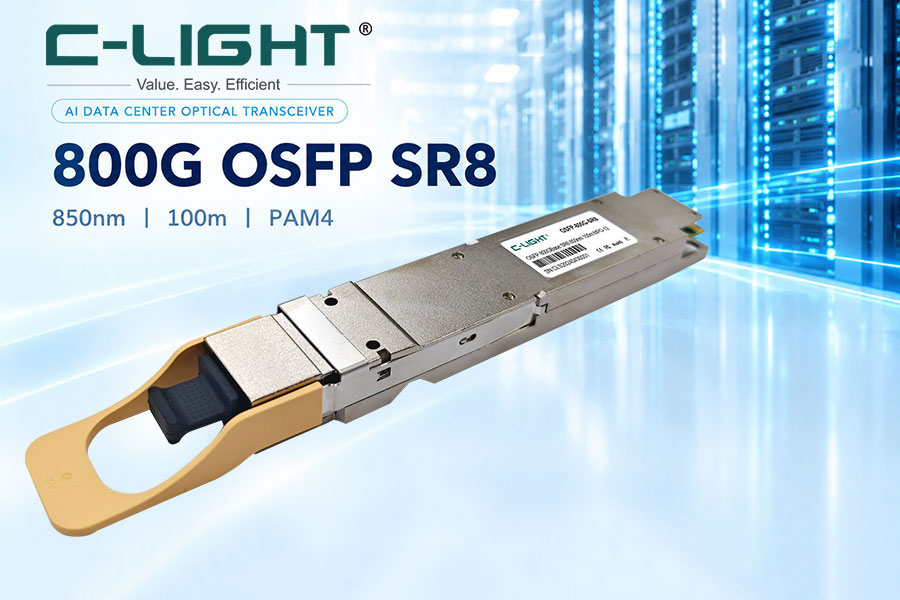
800G SR8 is a short-reach optical transceiver architecture designed primarily for multimode fiber. It typically uses eight parallel optical lanes, with each lane carrying approximately 100Gbps.
800G SR8 commonly operates around 850nm and uses VCSEL-based optical technology. It is intended for short-distance data center connectivity and can support links up to approximately 100m depending on the fiber type and specification.
11. What Is 800G DR8?
800G DR8 is a single-mode fiber architecture designed for medium-reach data center connections. It uses parallel optical transmission rather than wavelength multiplexing across each fiber pair.
C-LIGHT's current 800G product portfolio specifies DR8 configurations with reach up to approximately 500m, providing an option between short-reach multimode solutions and longer-reach WDM architectures.
12. What Is 800G 2xFR4?
800G 2xFR4 combines two 400G FR4 optical sections into one 800G module. Each 400G section can use multiple LAN-WDM wavelengths, allowing several optical channels to share a fiber pair.
This architecture reduces the number of fibers required compared with fully parallel optical transmission and can support approximately 2km reach in typical implementations.
13. What Is 800G VR8?
VR8 is a short-reach 800G optical architecture used for very short data center and AI cluster connections. C-LIGHT's current 800G OSFP portfolio includes VR8 configurations with reach up to approximately 50m.
VR8 is optimized for applications where switches, GPU systems, and other network equipment are physically close together.
14. 800G SR8 vs. DR8 vs. 2xFR4
| Parameter | 800G SR8 | 800G DR8 | 800G 2xFR4 |
|---|---|---|---|
| Fiber Type | MMF | SMF | SMF |
| Optical Architecture | 8 Parallel Lanes | 8 Parallel Lanes | 2 × 400G WDM Sections |
| Typical Wavelength | 850nm | LAN-WDM region | LAN-WDM region |
| Typical Reach | Up to 100m | Up to 500m | Up to 2km |
| Fiber Efficiency | Lower | Higher | Higher |
| Typical Application | Short data center links | Medium-reach DCI | Campus and longer data center links |
15. What Optical Wavelengths Are Used in 800G Modules?
The wavelength depends on the specific optical architecture. Short-reach multimode solutions such as SR8 commonly use approximately 850nm VCSEL technology.
Single-mode solutions such as DR8 and 2xFR4 commonly use wavelength regions around 1310nm, with some configurations using LAN-WDM channels to transport multiple optical lanes over fewer fibers.
16. Why Does 800G Use Multiple Optical Lanes?
Using multiple lanes distributes the aggregate bandwidth across several transmit and receive channels. This allows the optical and electrical components to operate within realistic per-lane speed and bandwidth requirements.
For example, an eight-lane architecture can combine eight approximately 100G-class lanes to create the required 800G aggregate bandwidth.
17. 800G Parallel Optics vs. WDM
Parallel optics uses separate fibers for individual optical channels, while WDM combines multiple wavelengths onto fewer fibers.
Parallel optics can provide a relatively straightforward optical architecture, while WDM improves fiber utilization and can reduce the number of fibers required for longer connections. The trade-off involves optical complexity, wavelength control, insertion loss, and system cost.
18. 800G and Optical Fiber Type
800G modules can use either multimode fiber or single-mode fiber depending on the transmission distance and optical architecture.
MMF-based solutions are generally intended for shorter data center connections, while SMF-based solutions provide greater reach and support WDM architectures for longer links.
19. 800G and Connector Types
The connector depends on the optical lane architecture. Parallel 800G modules commonly use MPO-family connectors, while WDM modules may use duplex LC, LC/APC, or other optical interfaces depending on the implementation.
Connector selection must match the number of optical lanes, fiber type, polarity, insertion-loss requirements, and host deployment architecture.
20. 800G Optical Link Budget
Optical link budget is particularly important when selecting an 800G module for a real deployment. The available power margin depends on transmitter launch power, receiver sensitivity, fiber attenuation, connector loss, splice loss, passive component loss, and other optical penalties.
A module's maximum reach should therefore not be interpreted as a universal distance independent of the installed fiber path.
21. 800G and Receiver Sensitivity
Receiver sensitivity defines the minimum optical input level required for the receiver to achieve the specified performance under defined conditions.
For longer-reach 800G links, receiver sensitivity becomes particularly important because fiber attenuation and passive-component losses consume more of the available optical budget.
22. 800G and Optical Power
Transmitter launch power contributes directly to the available optical budget. However, increasing launch power is not a universal solution for improving reach because receiver overload limits, dispersion, nonlinear effects, and waveform quality also need to be considered.
A valid optical design must remain within both transmitter and receiver operating specifications.
23. 800G and Optical DSP
Some 800G optical transceivers use DSPs to compensate for electrical and optical channel impairments. DSP functions can include equalization, signal recovery, and other high-speed signal-processing functions.
The exact role of the DSP depends on the module architecture, lane rate, reach, modulation format, and host interface.
24. 800G and LPO
LPO, or Linear Pluggable Optics, is an alternative architecture that reduces or eliminates conventional DSP processing inside the optical module and relies more heavily on the host ASIC and SerDes for signal conditioning.
800G is an important application area for LPO because reducing module DSP power can be valuable in high-density AI switches. However, LPO places greater requirements on the host electrical channel and system interoperability.
25. 800G and FEC
Forward Error Correction adds redundant information that allows the receiver to detect and correct a defined level of transmission errors. FEC is important in high-speed Ethernet because raw channel error performance becomes more difficult to control as lane rates increase.
The optical module and system must remain within the operating range of the selected FEC implementation.
26. 800G and OMA
Optical Modulation Amplitude is an important transmitter parameter for high-speed optical modules. It describes the optical amplitude separation between defined signal levels.
For PAM4-based 800G transmitters, OMA or OMAouter must be considered together with eye quality, TDECQ, optical power, and receiver sensitivity.
27. 800G and TDECQ
TDECQ is used to evaluate PAM4 transmitter quality by quantifying effective eye closure under a defined measurement methodology.
Because 800G optical modules commonly use PAM4, TDECQ provides important information about transmitter waveform quality that cannot be obtained from average optical power or OMA alone.
28. 800G and BER
BER measures the ratio of incorrectly received bits to total tested bits. It provides an end-to-end indication of digital transmission performance.
High BER can result from insufficient optical power, transmitter degradation, receiver limitations, dispersion, electrical channel loss, crosstalk, jitter, or interoperability problems.
29. 800G and Electrical Signal Integrity
The electrical channel between the host ASIC and optical module is a critical part of an 800G link. PCB traces, connectors, packages, cages, and module interfaces introduce insertion loss, return loss, crosstalk, and other impairments.
As lane rates approach 100G and beyond, maintaining adequate electrical margin becomes increasingly important.
30. 800G Optical Transceiver Power Consumption
Power consumption is a major design consideration for high-density 800G switches. The total power of a module includes the optical transmit and receive components, driver and TIA circuitry, DSP where present, monitoring circuits, and thermal-management requirements.
OSFP and other high-speed packaging approaches are designed to accommodate the thermal requirements of next-generation optical modules.
31. 800G Optical Transceiver Thermal Management
High-speed optical modules generate significant heat, particularly when DSPs and other active signal-processing components are included.
Thermal design can involve module heat sinks, switch airflow, thermal interfaces, chassis design, and controlled operating conditions. Adequate thermal management helps maintain stable optical power, wavelength, and electrical performance.
32. 800G for AI Data Centers
AI workloads create substantial east-west traffic between GPUs, switches, accelerators, storage systems, and other components. 800G optical transceivers provide the bandwidth density required for high-capacity AI fabrics.
Short-reach SR8 and VR8, medium-reach DR8, and WDM-based FR4 solutions can address different physical distances within AI and hyperscale environments.
33. 800G for GPU Cluster Interconnects
GPU clusters require high-bandwidth connections with low latency and predictable performance. 800G optical connectivity can be used for switch-to-GPU, switch-to-switch, and fabric interconnects where the physical topology requires higher bandwidth than 400G ports can provide.
Both Ethernet and InfiniBand architectures can use 800G-class optical connectivity depending on the platform and optical module implementation.
34. 800G for Hyperscale Data Centers
Hyperscale environments require high port density and efficient use of rack space, power, and fiber infrastructure. 800G modules provide a path toward higher aggregate switch bandwidth while reducing the number of ports required for a given traffic load.
Module selection depends on reach, switch platform, fiber infrastructure, power budget, and operational requirements.
35. 800G for High-Performance Computing
HPC systems depend on high-bandwidth, low-latency networking between compute nodes and switching infrastructure. 800G optical modules can provide high-density connectivity for large compute clusters.
The exact transceiver architecture depends on the network protocol, topology, fiber distance, and host interface.
36. 800G Ethernet
800G Ethernet provides a high-capacity network interface for next-generation switching systems. Optical modules may implement the 800G interface through multiple PAM4 lanes and different optical lane architectures.
As switch ASIC bandwidth continues to increase, 800G optical transceivers provide an important physical-layer connectivity option between high-capacity network ports.
37. 800G InfiniBand
800G optical connectivity is also relevant to high-performance computing and AI systems using InfiniBand architectures. C-LIGHT's 800G OSFP portfolio supports InfiniBand NDR applications.
The appropriate optical module depends on the InfiniBand platform, host interface, link distance, fiber infrastructure, and connector configuration.
38. 800G Data Center Interconnect
For data center interconnect, the required reach can range from short campus connections to several kilometers or longer. Standard short-reach 800G SR8 or DR8 modules are not interchangeable with longer-reach solutions simply because all are rated at 800G.
WDM-based FR4, LR-class, and coherent solutions can be considered when the distance exceeds the practical range of short-reach parallel optics.
39. 800G QSFP-DD Compatibility
800G QSFP-DD modules should be evaluated for mechanical, electrical, optical, management, and host-platform compatibility. Nominal 800G support alone does not guarantee interoperability between every switch and transceiver.
Vendor coding, lane mapping, CMIS behavior, firmware, optical architecture, and host SerDes capability can all affect deployment.
40. 800G OSFP Compatibility
OSFP modules use a different mechanical ecosystem from QSFP-DD. Before deployment, the switch cage, host electrical interface, module power specification, firmware support, connector arrangement, and optical architecture must be checked.
Using an OSFP module also requires a compatible host platform designed to accept the OSFP form factor.
41. 800G Optical Transceiver Applications
Typical applications include AI data centers, GPU clusters, hyperscale cloud infrastructure, high-performance computing, 800G Ethernet, switch-to-switch connections, and data center interconnects.
The appropriate module should be selected based on required distance, fiber type, topology, port density, optical budget, power envelope, and host compatibility.
42. How to Choose an 800G Optical Transceiver?
Start with the host switch or NIC interface and determine whether the platform supports OSFP or QSFP-DD. Next, determine the required transmission distance and fiber type.
For short multimode links, SR8 or VR8 may be appropriate. For medium-reach single-mode links, DR8 can be considered. For longer single-mode links, WDM-based 2xFR4, LR, or coherent architectures may provide the required reach.
Finally, verify optical budget, connector type, power consumption, thermal conditions, management protocol, vendor compatibility, and the complete system specification.
43. What Is the Difference Between 800G Optical Transceiver and 800G DAC?
An 800G optical transceiver uses optical fiber and converts electrical signals into optical signals, while an 800G DAC carries the signal directly over copper.
Optical 800G modules support longer reach and flexible fiber routing, while 800G DAC is intended primarily for very short connections where low cost, low power, and low latency are priorities.
44. What Is the Difference Between 800G Optical Transceiver and 800G AEC?
An 800G AEC is an active electrical copper interconnect that uses embedded electronics to condition the electrical signal. An 800G optical transceiver converts the signal into optical form and transmits it over fiber.
AEC can extend the practical reach of copper compared with passive DAC, while optical transceivers are better suited to applications requiring greater physical distance or fiber connectivity.
45. 800G Optical Transceiver Testing
800G module validation can include transmitter optical power, receiver sensitivity, wavelength, OMA, TDECQ, eye diagrams, BER, jitter, temperature performance, lane-to-lane consistency, and electrical signal-integrity measurements.
For deployment validation, interoperability testing with the actual switch, NIC, GPU platform, fiber plant, and associated optical components is also important.
46. 800G Optical Transceiver Troubleshooting
When an 800G link fails to establish or shows errors, the first checks should include module recognition, host compatibility, fiber polarity, connector cleanliness, optical power, and configuration.
If the optical path is healthy, investigate electrical channel quality, lane mapping, firmware, FEC status, temperature, BER, and interoperability. Because 800G systems contain multiple high-speed lanes, lane-specific diagnostics can be valuable.
47. The Evolution From 400G to 800G
800G represents an important increase in port bandwidth compared with 400G. The transition requires higher-speed electrical lanes, improved optical components, stronger signal integrity, better thermal management, and more efficient module architectures.
PAM4, advanced DSP, improved optical engines, LPO, and higher-density packaging are all part of the broader technology evolution surrounding 800G networking.
48. 800G and the Transition to 1.6T
800G is also an important stepping stone toward 1.6T optical networking. The next generation increases lane rates and may use 200G-per-lane architectures, creating significantly tighter electrical and optical requirements.
Technologies developed for 800G, including PAM4, advanced optical engines, thermal management, and high-speed electrical interfaces, provide part of the foundation for future 1.6T systems.
49. 800G Optical Transceiver FAQ
Q1. What is an 800G optical transceiver?
Q2. What is the difference between 800G OSFP and 800G QSFP-DD?
Q3. What is the difference between 800G SR8, DR8, and 2xFR4?
Q4. Does 800G use PAM4?
Q5. What fiber is used for 800G optical transceivers?
Q6. What applications use 800G optical transceivers?
50. Summary
An 800G optical transceiver is a high-bandwidth optical connectivity solution designed for the rapidly increasing data requirements of AI, HPC, hyperscale, and next-generation Ethernet networks. Modern 800G modules commonly use PAM4 and multi-lane architectures and are available in OSFP and QSFP-DD form factors. SR8 and VR8 address short-reach multimode connectivity, DR8 provides medium-reach single-mode connectivity, while 2xFR4, LR, and coherent architectures extend the usable distance. Selecting the correct 800G module requires a complete evaluation of host compatibility, lane architecture, fiber type, wavelength, connector, optical budget, power, thermal conditions, and transmission distance.
 >
>

 >
>
 >
>
 >
>
 >
>
 >
>
 >
>
 >
>