TEL:+86 132 6656 7067




Single-Mode Fiber (SMF) and Multimode Fiber (MMF) are the two major types of optical fiber used in modern communication networks. Both transmit data using light, but their core structures, propagation characteristics, wavelengths, transmission distances, and typical applications are different.
SMF is designed to support essentially one propagation mode through a very small fiber core, making it suitable for longer-distance and high-bandwidth transmission. MMF has a larger core that supports multiple propagation modes and is widely used for short-reach data center and enterprise connections.
Choosing between SMF and MMF depends on transmission distance, optical transceiver type, wavelength, required bandwidth, cabling infrastructure, power budget, network architecture, and future expansion plans.
1. What Is SMF?
SMF stands for Single-Mode Fiber. It uses a small optical core that allows the fiber to support primarily one propagation mode at the operating wavelength.
The reduced modal propagation makes SMF suitable for high-bandwidth and longer-distance communication systems.
2. What Is MMF?
MMF stands for Multimode Fiber. It has a larger core than SMF and allows multiple light propagation modes to travel through the fiber.
MMF is commonly used for short-distance networking because it can support efficient coupling with relatively low-cost optical sources such as VCSELs.
3. SMF vs MMF at a Glance
| Feature | SMF | MMF |
|---|---|---|
| Full name | Single-Mode Fiber | Multimode Fiber |
| Core size | Typically around 9 µm | Typically 50 µm or 62.5 µm |
| Propagation modes | Primarily one | Multiple |
| Typical wavelength | 1310 nm and 1550 nm, among others | Commonly 850 nm for data center applications |
| Typical reach | Hundreds of meters to many kilometers depending on optics | Generally short reach |
| Common fiber families | OS1, OS2 and related SMF categories | OM1, OM2, OM3, OM4 and OM5 |
| Typical optical source | Laser-based transmitters | VCSEL-based transmitters are common |
| Common applications | Telecom, DCI, enterprise and long-reach data center links | Short-reach data center and enterprise links |
4. The Fundamental Difference
The main difference is the number of optical propagation modes supported by the fiber.
SMF is designed to restrict propagation to essentially one mode, while MMF allows multiple modes to propagate simultaneously.
This difference affects modal dispersion, transmission distance, bandwidth characteristics, connector coupling, and the type of optical transceiver that can be used.
5. SMF Core Size
Common single-mode fiber used in telecommunications and data communications has a core diameter of approximately 8 to 10 µm, often described as 9/125 µm fiber.
The small core requires more precise optical alignment but significantly reduces modal propagation differences.
6. MMF Core Size
Modern multimode fiber commonly uses a 50/125 µm core and cladding structure. Older systems can also use 62.5/125 µm fiber.
The larger core simplifies optical coupling and is well suited to short-reach optical transmitters.
7. Why Core Size Matters
Core size influences how light is coupled into the fiber and how many propagation modes can travel through it.
The small SMF core supports highly controlled propagation, while the larger MMF core supports many modes. These different propagation characteristics are a major reason why the two fiber types have different reach and bandwidth behavior.
8. Propagation Modes in SMF
At its intended operating wavelength, SMF supports essentially one dominant propagation mode.
As different modes do not travel through the fiber in the same way as in MMF, modal dispersion is greatly reduced.
9. Propagation Modes in MMF
MMF supports multiple modes that can take different optical paths through the fiber core.
These modes can arrive at different times at the receiver, producing modal dispersion and limiting transmission distance at high data rates.
10. Modal Dispersion
Modal dispersion is particularly important in MMF.
Different propagation modes can travel different effective optical paths and arrive at slightly different times. As data rate increases or distance becomes longer, this timing spread can reduce the available signal margin.
11. SMF and Modal Dispersion
Because SMF is designed for essentially single-mode propagation, modal dispersion is greatly reduced compared with MMF.
This is one of the main reasons SMF is suitable for long-distance and very high-bandwidth optical communication.
12. Wavelength
SMF and MMF are commonly associated with different operating wavelength regions.
SMF data communication frequently uses wavelengths around 1310 nm and 1550 nm, while MMF data center optics are commonly associated with the 850 nm region.
13. Why MMF Uses 850 nm
The approximately 850 nm wavelength region is well established for short-reach multimode systems using VCSEL transmitters.
VCSELs can provide compact, efficient optical sources suitable for high-density parallel optical transmission over MMF.
14. Why SMF Uses 1310 nm and 1550 nm
SMF supports the wavelength ranges commonly used for data communication and telecommunications, including approximately 1310 nm and 1550 nm.
These wavelength regions provide low-loss transmission characteristics and support a wide range of single-mode optical architectures.
15. SMF Transmission Distance
SMF can support distances ranging from short data center links to metropolitan, long-haul, and other extended optical connections.
The actual reach is determined by the optical transceiver, transmitter power, receiver sensitivity, fiber attenuation, dispersion, wavelength, FEC, and total link budget.
16. MMF Transmission Distance
MMF is generally optimized for shorter distances.
The maximum reach depends on the MMF category, modal bandwidth, wavelength, data rate, transceiver design, and optical power budget.
Higher-speed applications generally require more capable MMF such as OM3, OM4, or OM5.
17. SMF Is Not Always Longer Reach
SMF has a strong advantage for long-reach transmission, but fiber type alone does not define the distance of a network link.
The optical module and transmission standard determine the actual supported reach. A short-reach SMF module and a long-reach SMF module may use the same basic fiber type while supporting very different distances.
18. MMF Is Not Always Low Bandwidth
Modern MMF can support very high data rates over short distances.
OM4 and OM5 fiber are widely used for high-speed data center transmission, including applications based on 100G, 200G, 400G, and selected higher-speed parallel architectures.
19. Bandwidth Characteristics
SMF provides excellent bandwidth potential because modal dispersion is minimized.
MMF can also provide high bandwidth, but its modal characteristics become an increasingly important limitation as distance and data rate increase.
20. Attenuation
Fiber attenuation is the reduction in optical power as light travels through the fiber.
SMF can provide very low attenuation at common telecom wavelengths, while MMF performance depends on its wavelength and fiber category.
Total system loss also includes connectors, splices, passive components, and other optical elements.
21. Dispersion
Dispersion describes the spreading of an optical signal as it propagates through a fiber.
MMF is strongly influenced by modal dispersion, while SMF avoids most modal-dispersion effects but can still experience chromatic dispersion and other wavelength-dependent effects.
22. Chromatic Dispersion
Chromatic dispersion occurs because different spectral components of an optical signal can propagate at different velocities.
It exists in SMF and MMF, although its impact depends on the fiber, wavelength, transmitter spectral characteristics, data rate, and link distance.
23. SMF Optical Sources
SMF systems commonly use laser sources such as DFB lasers, EMLs, or other semiconductor laser architectures.
These sources provide the optical characteristics required for single-mode transmission and are available across a wide range of speeds and reaches.
24. MMF Optical Sources
MMF data center systems commonly use VCSEL-based transmitters.
VCSELs are well suited to multimode fiber because the larger MMF core allows efficient coupling and supports compact parallel transmitter architectures.
25. Coupling SMF
The small SMF core requires precise alignment between the optical source and fiber.
This makes connector alignment, transceiver optical design, and manufacturing tolerances important considerations in single-mode systems.
26. Coupling MMF
The larger MMF core provides greater tolerance for optical coupling compared with SMF.
This is one reason short-reach multimode systems can use compact VCSEL transmitters and relatively straightforward optical packaging.
27. SMF Connector Types
SMF systems can use connectors such as LC, SC, MPO-family connectors, and other high-density interfaces depending on the optical architecture.
The connector does not define whether a fiber is single-mode. Fiber type and connector type are separate specifications.
28. MMF Connector Types
MMF systems can also use LC, MPO-family, and other connector types.
For high-density parallel optical systems, multi-fiber connectors are commonly used to accommodate multiple transmit and receive lanes.
29. LC Does Not Mean SMF
LC is a connector interface, not a fiber type.
LC connectors can be used with both single-mode and multimode fiber. The fiber type must therefore be verified separately from the connector.
30. MPO Does Not Mean MMF
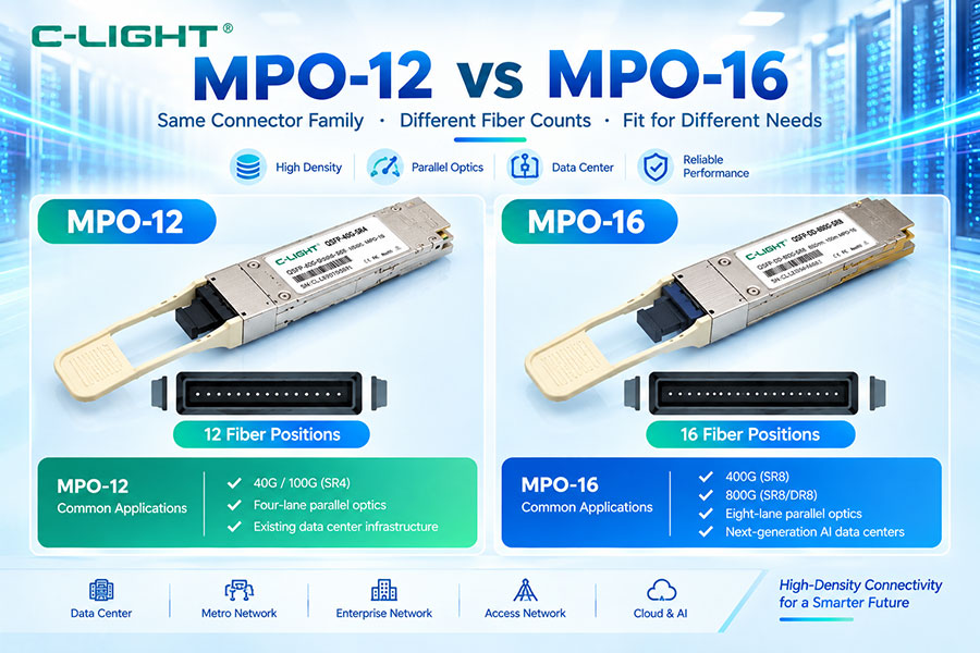
MPO is a multi-fiber connector family and can be used with both single-mode and multimode fiber.
For example, MPO can be used in single-mode parallel optics as well as multimode parallel optics.
31. SMF in Data Centers
SMF is widely used in modern data center networks when the required distance, optical architecture, or network density exceeds the practical range of multimode systems.
Single-mode fiber is particularly common in inter-rack, spine-leaf, data center interconnect, and higher-reach optical links.
32. MMF in Data Centers
MMF remains important for short-reach data center connections.
It can provide economical and efficient optical connectivity between equipment located within the same rack or within short distances across a data center floor.
33. SMF for 100G
100G optical modules are available in both single-mode and multimode architectures.
SMF is commonly used for duplex WDM links and parallel single-mode links, while MMF is used for short-reach parallel architectures.
34. MMF for 100G
100G MMF systems commonly use 850 nm-class VCSEL-based parallel optical transmission.
Examples include short-reach multimode architectures using multiple optical lanes and multi-fiber connectors.
35. SMF for 400G
400G networks use a wide range of single-mode architectures.
Examples include 400G DR4, FR4, LR4, and other implementations using parallel single-mode or WDM transmission.
36. MMF for 400G
MMF remains relevant for short-reach 400G systems.
400G SR8 is a representative parallel multimode architecture using multiple optical lanes over multimode fiber.
37. SMF for 800G
800G optical systems increasingly use single-mode fiber for parallel and WDM architectures.
Examples include 800G DR8 and various WDM-based solutions, depending on the target reach and optical design.
38. MMF for 800G
MMF can also support selected 800G short-reach architectures.
High-density VCSEL arrays and parallel multimode transmission can provide the optical lanes required for suitable short-reach applications.
39. SMF vs MMF in AI Data Centers
AI data centers can use both fiber types because network links have different physical distances and optical architectures.
MMF can be suitable for short parallel connections where power and cost are important, while SMF provides greater flexibility for longer links and WDM architectures.
40. OS2 Fiber
OS2 is a commonly used single-mode fiber category for outside-plant and data communication applications.
It is widely used with 1310 nm and 1550 nm optical systems and can support long-reach networking when paired with suitable transceivers.
41. OM3 Fiber
OM3 is a 50/125 µm multimode fiber designed for high-speed short-reach data communication.
It has a higher modal bandwidth than earlier multimode categories and is commonly used with 850 nm VCSEL-based systems.
42. OM4 Fiber
OM4 is also a 50/125 µm multimode fiber but provides higher modal bandwidth than OM3.
This can support greater reach or higher-performance short-reach links, depending on the specific optical transceiver.
43. OM5 Fiber
OM5 is a 50/125 µm wideband multimode fiber designed to support multiple short wavelengths.
Its wider wavelength capability makes it useful for wavelength-multiplexed multimode architectures, although at a single 850 nm wavelength it is not simply a universal replacement for OM4.
44. SMF vs MMF Cost
Cost must be considered at the system level rather than simply comparing the price of the fiber cable.
MMF systems can be economical for short links because VCSEL-based optics and multimode components are well established. SMF systems may provide better long-distance scalability and can reduce the need to use specialized parallel-fiber architectures for longer links.
45. Optical Transceiver Cost
The cost difference between SMF and MMF is also influenced by the transceiver.
Single-mode modules can require more sophisticated lasers and optical components, while multimode modules can benefit from highly integrated VCSEL arrays and short-reach optical architectures.
46. Cabling Flexibility
SMF generally provides greater flexibility for network expansion because the same fiber infrastructure can support a wide range of reach classes and optical architectures.
MMF is highly effective for short-reach environments but has more limited long-distance application due to modal characteristics.
47. Future-Proofing
Future network requirements should be considered before selecting fiber.
If future links may require greater distance, higher bandwidth, or WDM architectures, SMF can provide a broad infrastructure platform. If the environment is strictly short-reach and optimized for multimode optics, OM4 or OM5 may be appropriate.
48. Common SMF and MMF Selection Mistakes
One common mistake is choosing fiber based only on connector type. Another is selecting fiber based only on the current transceiver without considering future upgrades.
Other mistakes include mixing incompatible fiber categories, ignoring transceiver specifications, exceeding the supported reach, and failing to account for connector and splitter losses.
49. Fiber Type Must Match the Transceiver
The optical transceiver and fiber should always be considered together.
An 850 nm multimode transceiver should be paired with an appropriate multimode fiber, while a single-mode transceiver should be deployed with compatible single-mode infrastructure unless the specific design states otherwise.
50. SMF vs MMF Selection Guide
| Requirement | SMF | MMF |
|---|---|---|
| Very short data center link | Suitable | Highly suitable |
| Longer reach | Highly suitable | Limited |
| WDM architecture | Highly suitable | Possible in specific designs |
| 850 nm VCSEL systems | Less typical | Highly suitable |
| 1310 nm systems | Highly suitable | Less typical |
| 400G DR4 | Common | Not typical |
| 400G SR8 | Not typical | Common |
| 800G parallel optics | Common | Possible for selected short-reach architectures |
| Future long-reach expansion | Strong | Limited |
51. SMF vs MMF Core Comparison
| Parameter | SMF | MMF |
|---|---|---|
| Typical core diameter | Approximately 9 µm | 50 µm or 62.5 µm |
| Typical cladding diameter | 125 µm | 125 µm |
| Modes | Primarily one | Multiple |
| Modal dispersion | Very low | Significant factor |
| Coupling tolerance | More demanding | More tolerant |
| Typical source | Laser | VCSEL |
52. SMF vs MMF Performance Comparison
| Performance Factor | SMF | MMF |
|---|---|---|
| Long-distance transmission | Excellent | Limited |
| Short-reach transmission | Excellent | Excellent |
| Modal dispersion | Low | Higher |
| WDM potential | High | Available in selected architectures |
| High-speed scalability | High | Strong for short reach |
| Source integration | Laser-based | VCSEL-based arrays are common |
| Typical wavelength | 1310/1550 nm | 850 nm |
53. SMF vs MMF Is Not Simply Long Distance vs Short Distance
Reach is an important distinction, but it is not the only one.
The choice also affects the optical source, wavelength, transceiver architecture, connector configuration, modal bandwidth, cost structure, and future network expansion options.
54. SMF vs MMF for New Data Center Projects
For a new data center, the selection should begin with the optical roadmap rather than a single current application.
Consider expected switch speeds, rack distances, spine-leaf topology, transceiver roadmap, WDM requirements, cabling density, and planned network upgrades before selecting the fiber infrastructure.
55. SMF vs MMF for Legacy Infrastructure
Existing infrastructure can strongly influence the decision.
If a facility already has OM3 or OM4 multimode cabling, short-reach MMF optics may remain practical. If the network is being redesigned for longer reach or a new high-speed optical architecture, SMF may provide greater flexibility.
56. SMF vs MMF and Optical Budget
Both fiber types require optical budget analysis.
The total loss includes fiber attenuation, connector loss, splice loss, passive component loss, and engineering margin. The optical transceiver must provide sufficient transmit power and receive sensitivity for the complete link.
57. SMF vs MMF and Maintenance
Both fiber types require clean connectors, proper polarity, correct patching, and appropriate testing.
MMF systems may be easier to couple and terminate, while SMF systems require more precise optical alignment and can be more sensitive to connector quality.
58. SMF vs MMF and Network Upgrades
The fiber infrastructure can remain in service across multiple transceiver generations when the new optical modules are compatible with the existing fiber.
However, reach, wavelength, connector type, polarity, and optical budget must be rechecked during every major upgrade.
59. How to Choose SMF or MMF
Choose SMF when the network requires longer reach, single-mode optical architectures, 1310 nm or 1550 nm transmission, WDM, or broad future expansion flexibility.
Choose MMF when the network focuses on short-reach connectivity, 850 nm VCSEL-based transmission, high-density parallel optics, and an existing OM3, OM4, or OM5 infrastructure.
60. Conclusion
SMF and MMF are both essential fiber technologies, but they are designed around different optical propagation characteristics. SMF uses a small core and primarily single-mode propagation, making it highly suitable for long-reach, high-bandwidth, single-mode, and WDM optical systems. MMF uses a larger core with multiple propagation modes and is particularly effective for short-reach data center and enterprise links.
The correct choice is not determined by fiber type alone. The optical transceiver, wavelength, transmission distance, lane architecture, connector, optical budget, network topology, and future upgrade requirements must all be considered together.
For modern 400G, 800G, and emerging 1.6T networks, both SMF and MMF remain relevant. MMF continues to serve short-reach parallel optical applications, while SMF provides a broader platform for single-mode, WDM, and longer-reach connectivity.
 >
>

 >
>
 >
>
 >
>
 >
>
 >
>
 >
>
 >
>