TEL:+86 132 6656 7067





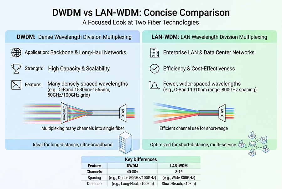
DWDM and DCI-WDM address different aspects of optical network deployment. Dense wavelength-division multiplexing (DWDM) is a technology that carries multiple optical wavelengths over the same fiber. DCI-WDM generally describes an integrated wavelength-division transmission system optimized for data center interconnect applications, combining supported optical interfaces and transmission functions into a deployment-oriented platform.
The distinction is therefore not simply one optical technology versus another. A DCI-WDM system can use DWDM as its underlying transmission method. The practical decision concerns whether to assemble a DWDM solution from separate components or deploy an integrated system designed around data center interconnection requirements.
1. What Is the Difference Between DWDM and DCI-WDM?
DWDM defines how multiple optical channels can share a fiber by operating at different wavelengths. A DWDM network may include transceivers, wavelength multiplexers and demultiplexers, optical amplifiers, optical switching equipment, and a transport management platform.
DCI-WDM typically refers to an integrated transmission system tailored to the needs of connecting data centers. Depending on the product design, it may incorporate client service ports, wavelength transmission functions, equipment-level management, protection mechanisms, and a compact rack-mount chassis.
| Comparison Factor | DWDM Technology or System | Integrated DCI-WDM System |
|---|---|---|
| Definition | Optical wavelength multiplexing technology and the systems built around it | A product or solution category designed for data center interconnection |
| Primary objective | Carry multiple optical channels over shared fiber infrastructure | Provide a practical, integrated transmission solution for interconnecting data centers |
| Architecture | May use separate transceivers, mux/demux units, amplifiers, and transport equipment | May integrate supported service interfaces and transmission functions into a compact platform |
| Deployment approach | Can be modular and engineered around individual optical components | Can reduce component-level integration and cabling work within the supported design |
| Capacity | Depends on wavelength count, channel rates, spectrum, and line-system limits | Depends on the device's supported interfaces, internal architecture, and expansion capability |
| Protection | Depends on the selected line protection and network architecture | May include integrated line-side or equipment-level protection, depending on the model |
| Best suited to | Flexible optical transport designs across varied network topologies | DCI deployments that align with the system's supported service and transmission requirements |
2. How a Conventional DWDM Solution Works
A conventional DWDM design combines optical signals at different wavelengths onto a common fiber path. At the destination, the optical channels are separated and delivered to the intended interfaces or transport equipment.
A deployment may use individual optical transceivers at the service interfaces, passive wavelength mux/demux equipment, and additional line-side components where the transmission distance and optical budget require them.
Typical DWDM components
DWDM optical transceivers: Generate or receive optical signals at supported wavelengths and data rates.
Multiplexers and demultiplexers: Combine optical channels onto shared fiber and separate them at the receiving end.
Optical amplifiers: Compensate for accumulated optical loss when required by the system design.
Optical add/drop equipment: Adds, drops, or routes selected wavelengths in supported network architectures.
Monitoring and management: Provides visibility into channel power, equipment status, and other available performance indicators.
This component-based approach offers flexibility. Engineers can select the required channel rates, optical interfaces, multiplexing capacity, amplification, and protection mechanisms according to the fiber route and traffic plan.
However, a modular design may require more individual components to be selected, installed, connected, configured, and maintained. The overall complexity depends on the architecture, not merely on whether the system uses DWDM.
3. How an Integrated DCI-WDM System Works
An integrated DCI-WDM platform is designed to simplify selected parts of the transmission system by placing supported client interfaces and optical transmission functions into a coordinated device. The equipment is commonly intended for point-to-point or metropolitan data center interconnection, although the precise topology and achievable distance depend on the model.
A typical deployment workflow includes:
Connect the supported client interfaces to the switches, routers, or other network equipment at each site.
Configure or select the system variant according to required service rates, fiber distance, and transmission conditions.
Connect the system to the intended inter-site fiber route.
Validate optical levels, link status, service continuity, and supported protection functions.
Monitor the deployed system through the management functions provided by the platform.
Depending on the product architecture, an integrated system can reduce the need for external optical jumpers or separately assembled components. It may also consolidate multiple client services within one chassis. These benefits are product-specific and should be verified against the device's interface configuration and deployment requirements.
4. DWDM vs DCI-WDM: Deployment and Installation
Installation effort is an important distinction between a modular optical design and an integrated DCI-WDM platform. A modular solution gives engineers freedom to build the network from individual components, while a pre-integrated system aims to reduce the integration work required for its supported application.
| Deployment Consideration | Modular DWDM Design | Integrated DCI-WDM Design |
|---|---|---|
| Component planning | Requires selection of the appropriate optical interfaces and supporting line-system components | Uses a defined platform and its supported interface configurations |
| Physical cabling | May require more connections between individual modules and passive optical equipment | May reduce internal component-level cabling through an integrated design |
| Installation | Depends on the number of components and the complexity of the optical architecture | Can be simpler when the site's requirements match the system's supported configuration |
| Configuration flexibility | Can support a broad range of custom architectures when appropriate components are available | Bound by the platform's supported rates, port types, capacity, and operating modes |
| Maintenance | Individual components may be diagnosed or replaced separately | Fault isolation and replacement depend on the system's internal design and service procedures |
| Expansion | May support additional channels or line-system components when capacity permits | Depends on supported stacking, chassis capacity, and model-specific expansion options |
An integrated system is not automatically easier to operate in every environment. A modular architecture may be preferable where the network has complex wavelength routing, unusual interface requirements, or an established optical management framework. An integrated platform may be more convenient when the link requirements match its built-in capabilities.
5. Capacity and Scalability
Neither DWDM nor DCI-WDM has a single fixed capacity. In a conventional DWDM network, aggregate capacity is influenced by the number of supported wavelengths, the data rate per wavelength, the available spectrum, and the optical performance of the line system.
For an integrated DCI-WDM platform, capacity is also constrained by the product's supported interfaces, internal switching or transmission architecture, chassis design, and expansion method.
| Capacity Factor | DWDM Design | DCI-WDM Platform |
|---|---|---|
| Aggregate throughput | Depends on supported channels and line-system configuration | Depends on the rated capacity and supported service-port configuration |
| Channel-rate upgrades | Require compatible transceivers and sufficient line-system performance | Require compatible ports and support within the product architecture |
| Additional wavelengths | Possible when spectrum and line-system capacity permit | Possible only if supported by the integrated design or its expansion options |
| System stacking | Depends on the chassis, optical topology, and management design | May be a documented expansion method for specific products |
| Fiber constraints | Limited by fiber availability and optical transmission conditions | Subject to the same physical fiber limits, alongside device-specific constraints |
Before planning an upgrade, distinguish between the capacity of each client port, the aggregate equipment capacity, and the capacity of the fiber transmission path. These values are not necessarily identical.
6. Transmission Distance and Optical Performance
Transmission distance is determined by the complete optical path rather than the DCI-WDM or DWDM label. Fiber attenuation, connector and splice losses, optical power levels, wavelength characteristics, and the receiver's operating requirements all influence whether a link can operate reliably.
For a modular DWDM design, the engineer can select compatible transceivers and additional line-system components to meet a specified route requirement. The resulting reach must be validated against the transmitter and receiver specifications and, where relevant, optical signal-to-noise ratio (OSNR) and amplifier performance.
An integrated DCI-WDM platform may be offered in variants intended for different distances or attenuation conditions. Selecting the appropriate model still requires information about the installed fiber route and its measured or estimated loss.
Confirm the actual route length and fiber type.
Estimate or measure total fiber and connector loss.
Verify transmit power and receiver operating limits.
Check whether amplification or other line-system equipment is required.
Validate link performance under the intended channel configuration.
Do not select equipment using distance alone. Two routes of equal length can have different losses and transmission characteristics because of fiber condition, splices, connector count, passive components, and intermediate equipment.
7. Protection, Reliability and Network Management
Protection mechanisms help maintain connectivity when a fiber route, power supply, fan, or other system component fails. Their availability and behavior depend on the specific DWDM equipment, integrated platform, and overall network topology.
Protection in a modular DWDM network
Protection can be designed through redundant line paths, optical protection equipment, redundant transport devices, and higher-layer network mechanisms. The exact response to a failure depends on where protection is implemented and whether a physically independent route is available.
Protection in an integrated DCI-WDM system
Some integrated platforms provide features such as line-side 1+1 protection or redundant power modules. These functions can simplify selected deployment designs, but the model's documentation must be consulted to verify the supported protection mode, switching behavior, and required physical connections.
| Reliability Requirement | What to Verify |
|---|---|
| Fiber-route protection | Availability of alternate paths and whether they are physically diverse |
| Power redundancy | Number of power modules, hot-swapping support, and independent power feeds |
| Equipment redundancy | Availability of backup devices, interfaces, or other replaceable components |
| Fault monitoring | Supported optical diagnostics, alarms, logs, and management interfaces |
| Service recovery | Protection switching behavior and end-to-end failover requirements |
A redundant power supply does not protect against a fiber cut, and two logical links do not guarantee physical route diversity. Reliability planning should address the entire path between the connected data centers.
8. Power Consumption, Rack Space and Operational Cost
Integrated DCI-WDM platforms can reduce rack space and simplify cabling by consolidating supported functions into a compact chassis. A modular DWDM design can also be efficient, but the complete footprint depends on the selected transceivers, multiplexers, amplifiers, transport equipment, and protection arrangement.
Power consumption should be assessed across all required components rather than inferred from chassis size or product category. An integrated system may consume less power in one deployment, while a modular solution may be more efficient in another, depending on the number of required channels, interfaces, and line-side components.
Cost evaluation should include:
Optical modules and transmission equipment.
Passive components, amplifiers, and any necessary protection hardware.
Installation labor and fiber patching.
Power, cooling, and rack-space requirements.
Management, maintenance, and replacement procedures.
Expansion costs as service bandwidth increases.
The best comparison uses an equivalent end-to-end configuration: the same client capacity, route distance, protection target, management requirements, and planned growth. Comparing a basic DWDM mux/demux setup with a fully protected integrated platform would not represent equivalent functionality.
9. Which Is Better for Different DCI Scenarios?
The choice depends on whether the deployment benefits more from component-level flexibility or a predefined integrated platform.
Many wavelengths or different channel rates must be combined.
The network requires custom optical routing or a more complex line-system design.
Engineers need to select individual transceivers, mux/demux equipment, and amplification.
The operator already manages a modular optical transport infrastructure.
The primary requirement is interconnecting data center sites.
The supported port rates and capacity match the traffic plan.
A compact rack-mounted solution is preferred.
Reduced component-level integration is valuable for deployment and maintenance.
Neither design is universally superior. A modular DWDM solution offers flexibility in component and line-system selection. An integrated DCI-WDM platform can provide a more consolidated deployment for applications covered by its product specifications.
10. C-LIGHT DCI-WDM and DWDM Product Options
C-LIGHT offers a dedicated DCI-WDM subsystem alongside DWDM optical products. These serve different parts of an interconnection design: the subsystem provides an integrated DCI-oriented platform, while individual DWDM transceivers support compatible wavelength-based optical architectures.
The listed platform uses a 1RU rack-mount chassis and is designed for data center interconnection. Published product information lists up to 1.6 Tbps per unit and expansion to 3.2 Tbps through stacking, subject to the supported configuration. Listed features also include line-side 1+1 protection and redundant power.
Confirm the exact interface count, service-port configuration, optical reach, protection arrangement, and total capacity with the product specification for the intended configuration.
DWDM transceiver options support compatible wavelength-based transmission designs. Selection depends on data rate, wavelength, reach, fiber loss, host compatibility, and the optical line system in use.
These components can be considered when building or expanding a modular DWDM architecture.
Coherent optical interfaces can support suitable high-capacity metro and transport links. Available data rates and transmission reach depend on the exact model and system architecture.
Verify the wavelength plan, OSNR requirements, host interface, and compatibility with the target line system.
Multiplexers and demultiplexers combine and separate supported optical channels. They are relevant to modular DWDM designs when the chosen interfaces and wavelength plan are compatible.
The required channel count, connector configuration, insertion loss, and wavelength range should be confirmed before deployment.
11. How to Select the Right Solution
A reliable comparison begins with the actual link requirements, not the equipment label. Document the service capacity, distance, fiber route, protection target, and operating environment before evaluating products.
| Selection Factor | Information to Confirm |
|---|---|
| Data rate | Required client-port rate and aggregate throughput |
| Port configuration | Interface type, port count, supported client protocols, and host compatibility |
| Transmission distance | Route length, fiber type, total optical loss, and receiver operating range |
| Optical architecture | Direct connection, modular DWDM, or an integrated DCI-WDM platform |
| Expansion plan | Expected traffic growth and supported capacity upgrades |
| Protection | Required line protection, power redundancy, and physical route diversity |
| Management | Supported alarms, diagnostics, interfaces, and monitoring procedures |
| Total cost | Equipment, cabling, installation, power, cooling, maintenance, and upgrades |
For a simple point-to-point DCI link, an integrated system may reduce installation complexity when it matches the required configuration. For a network with many wavelengths, custom routing, or specialized optical requirements, a modular DWDM architecture may offer greater design flexibility.
12. Common Deployment Mistakes
Assuming DCI-WDM is a separate wavelength standard
DCI-WDM is generally a product or solution description rather than a distinct wavelength multiplexing standard. Confirm which optical technology and interfaces the specific system supports.
Comparing different capacity configurations
Distinguish between per-port rate, aggregate chassis capacity, and capacity carried over the fiber path. Review the exact port configuration and expansion method rather than relying on a headline capacity alone.
Ignoring the fiber loss budget
A system designed for DCI still has physical transmission limits. Check route loss, connector condition, receiver limits, and the model-specific distance specification.
Assuming all protection functions are equivalent
Line-side 1+1 protection, redundant power supplies, equipment redundancy, and network-level route diversity solve different failure scenarios. Confirm the actual protection behavior.
Selecting components without checking interoperability
Verify service-port rates, optical characteristics, connector types, and compatibility with the equipment at both ends. Matching only the nominal speed or form factor is not sufficient.
13. Frequently Asked Questions
No. DWDM is a wavelength multiplexing technology. DCI-WDM generally describes an integrated WDM system or solution tailored for data center interconnect. A DCI-WDM product may use DWDM internally.
The exact optical technology depends on the product. Check the model's specifications for its wavelength plan, transmission interfaces, and line-system design rather than assuming all DCI-WDM products use the same configuration.
It can reduce component integration and internal cabling when the deployment matches its supported configuration. The installation effort still depends on the fiber route, interface configuration, protection requirements, and management needs.
Neither category has a universal capacity limit. A modular DWDM system depends on its supported wavelengths and channel rates, while an integrated DCI-WDM platform is constrained by its rated capacity and expansion options.
Some products provide line-side protection or redundant power functions. Confirm the specific model's protection design and remember that true route diversity requires appropriately independent physical paths.
A modular design may be preferable when the network requires custom wavelength planning, a broader mix of optical components, complex line-system functions, or expansion beyond the options supported by an integrated platform.
14. Conclusion
DWDM and DCI-WDM should be evaluated at different levels. DWDM describes the optical technology used to multiplex wavelengths over fiber, whereas DCI-WDM commonly identifies an integrated transmission platform designed for data center interconnect applications.
A modular DWDM design can provide flexibility in wavelength planning, optical components, and line-system architecture. An integrated DCI-WDM system can simplify deployment and consolidate supported functions in a compact platform. The right choice depends on required capacity, transmission distance, client interfaces, optical performance, protection, and future expansion.
For reliable selection, compare equivalent end-to-end configurations and verify the exact product specifications before deployment. This ensures that the chosen system matches the actual network requirements rather than relying on terminology alone.
Planning a data center interconnect deployment?
Review the required bandwidth, fiber distance, interface configuration, optical budget, and protection requirements when evaluating integrated DCI-WDM and modular DWDM options.
Contact C-LIGHT >

 >
 >
 >
 >
 >
 >
 >