TEL:+86 132 6656 7067




PIN and APD receivers are two common architectures for detecting optical signals in fiber optic communication systems. Both convert received light into electrical signals, but the photodetection mechanisms are different. A PIN receiver uses a PIN photodiode without internal avalanche multiplication, while an APD receiver uses an avalanche photodiode to provide internal gain.
This distinction affects more than the detector itself. Receiver sensitivity, bias voltage, noise, temperature control, electrical circuitry, power consumption and optical link margin can all change between the two approaches. PIN receivers are often used where a straightforward and efficient design is sufficient, while APD receivers can be useful when the system must detect weaker optical signals.
1. PIN vs APD Receiver at a Glance
| Feature | PIN Receiver | APD Receiver |
|---|---|---|
| Detector | PIN photodiode | Avalanche photodiode |
| Detection Principle | Direct photodetection | Photodetection with internal avalanche multiplication |
| Internal Gain | No avalanche gain | Yes |
| Bias Requirement | Relatively low | High reverse-bias voltage |
| Receiver Sensitivity | Good, depending on design | Can provide improved sensitivity |
| Noise | Relatively simple noise characteristics | Includes avalanche multiplication noise |
| Bias / Control Circuit | Simple | More complex |
| Temperature Management | Generally simpler | More demanding |
| Power Consumption | Often lower | Can be higher |
| Cost | Generally lower | Generally higher |
2. What Is a PIN Receiver?
A PIN receiver uses a PIN photodiode as the optical detector. When incoming photons reach the photodiode's active region, they generate electron-hole pairs and produce a photocurrent.
The photocurrent is then amplified and conditioned by receiver electronics, typically including a transimpedance amplifier or integrated receiver front end.
Because there is no avalanche multiplication stage, the receiver architecture is relatively straightforward and can be implemented with lower detector bias requirements.
3. What Is an APD Receiver?
An APD receiver uses an avalanche photodiode to detect incoming optical power. The APD operates under a relatively high reverse-bias voltage so that photo-generated carriers can trigger additional carrier generation through avalanche multiplication.
This creates internal electrical gain before the signal reaches the following amplifier stage. The additional gain can be valuable when the received optical signal is weak and the receiver requires greater sensitivity.
The benefit comes with additional requirements for high-voltage bias, gain control, temperature management and noise optimization.
4. Receiver Architecture: PIN vs APD
The receiver signal paths can be simplified as follows:
PIN Receiver: Optical Signal → PIN Photodiode → TIA / Receiver Electronics → Electrical Output
APD Receiver: Optical Signal → APD + Avalanche Gain → TIA / Receiver Electronics → Electrical Output
The extra multiplication stage is the defining architectural difference. APD creates additional electrical gain inside the photodetector itself, while PIN relies on the following receiver electronics for signal amplification.
5. Receiver Sensitivity
Receiver sensitivity represents the minimum optical input power required to meet a defined performance target, such as a specified bit-error ratio.
APD receivers can achieve better sensitivity because avalanche multiplication increases the electrical signal generated from a given amount of received light.
PIN receivers do not provide this internal gain, but a well-designed PIN receiver can still achieve strong sensitivity when the optical budget, detector and TIA are appropriately matched.
The actual sensitivity difference depends on wavelength, data rate, detector characteristics, TIA noise and the complete receiver design.
6. Optical Link Budget
The receiver type directly influences the available optical link margin because receiver sensitivity is one of the key terms in a link-budget calculation.
A simplified relationship is:
Maximum Allowable Loss = Transmitter Output Power − Receiver Sensitivity
If an APD receiver provides better sensitivity under the specified operating conditions, the system can have a larger allowable loss budget than an otherwise comparable PIN receiver.
However, this does not mean that APD automatically creates a fixed additional transmission distance. Fiber attenuation, connectors, splices, wavelength and transmitter performance still determine the actual link.
7. APD Avalanche Gain
APD gain results from impact ionization inside the avalanche region. The applied reverse-bias voltage creates the electric field needed to accelerate charge carriers and produce additional carriers.
The multiplication factor is controlled by the detector structure and operating conditions. The receiver therefore needs to maintain an appropriate APD bias level to achieve the intended performance.
This internal gain is the main technical reason APD receivers can be useful for low received-power applications.
8. Bias Voltage and Control
PIN and APD receivers differ significantly in their bias requirements.
PIN photodiodes generally use a comparatively simple bias arrangement. APDs require a much higher reverse-bias voltage and more precise control because avalanche multiplication is strongly linked to operating voltage.
An APD receiver may therefore need dedicated high-voltage generation, monitoring and control circuitry that is not required to the same extent in a conventional PIN design.
9. Noise Performance
PIN receivers have a relatively straightforward noise structure that includes detector shot noise, receiver thermal noise and electrical noise from the amplifier chain.
APD receivers introduce multiplication noise because the avalanche process is statistical. Increasing APD gain therefore does not produce unlimited improvement in signal-to-noise performance.
The optimum APD operating point is a balance between detector gain, multiplication noise, receiver noise and the required sensitivity.
10. Bandwidth and High-Speed Operation
Both PIN and APD receivers can support high-speed optical communication, but detector bandwidth depends on semiconductor structure, junction capacitance, carrier transit time, package parasitics and receiver electronics.
PIN designs can provide high-speed operation with relatively simple biasing. APD designs must balance avalanche gain against bandwidth, noise and operating voltage.
For high-speed optical modules, the detector should therefore be evaluated together with the TIA and the complete receiver front end rather than independently.
11. Temperature Effects
APD receivers are generally more sensitive to temperature because avalanche multiplication changes as the operating conditions change.
Temperature variation can alter the relationship between APD bias voltage and multiplication gain. Some APD receiver designs therefore incorporate bias compensation or monitoring to maintain a stable operating point.
PIN receivers normally have simpler bias and temperature-management requirements.
12. Power Consumption and Circuit Complexity
A PIN receiver generally requires less complicated bias circuitry because the detector does not need the high-voltage avalanche operating condition.
An APD receiver requires high-voltage bias generation and potentially additional monitoring or control circuitry. The complete receiver can therefore have greater electrical complexity and higher power requirements.
Actual power consumption depends on the detector, TIA, bias circuit and transceiver architecture.
13. PIN vs APD Receiver in ROSA
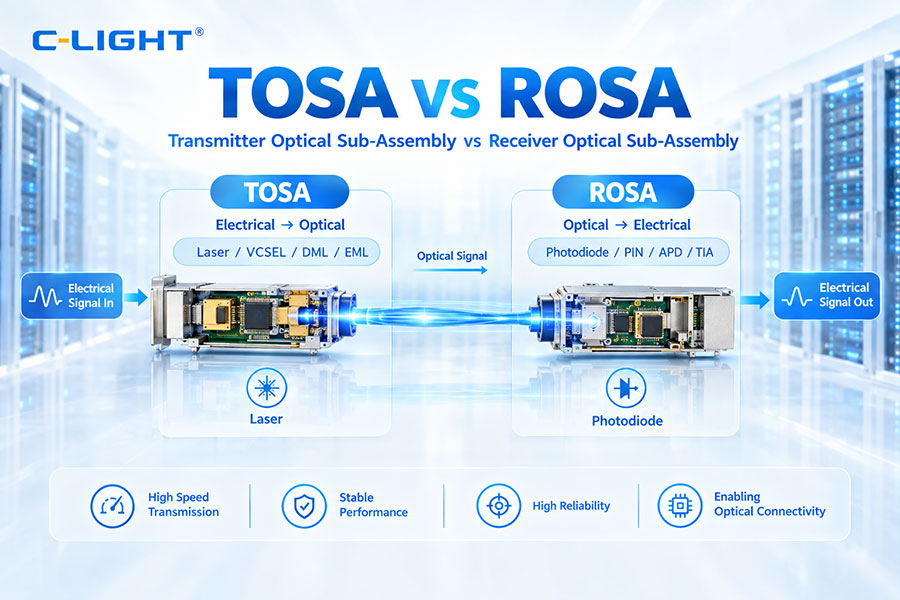
Both detector types can be integrated into a ROSA, or Receiver Optical Sub-Assembly.
| ROSA Configuration | Typical Characteristics |
|---|---|
| PIN-Based ROSA | Simple optical detection, lower bias requirements and straightforward receiver integration |
| APD-Based ROSA | Internal avalanche gain, higher bias requirements and greater sensitivity potential |
The ROSA choice depends on required sensitivity, data rate, wavelength, optical budget, temperature range and the electrical design of the host transceiver.
14. PIN vs APD Receiver in PON
PON systems are an important application for optical receivers because splitters and distribution fiber can reduce the optical power arriving at the ONU or ONT.
PIN receivers can be used where the available optical budget provides enough margin. APD receivers can be considered when the system requires additional detection sensitivity within the supported PON architecture.
The selection depends on the PON standard, split ratio, transmission distance, wavelength and receiver specifications.
15. PIN vs APD Receiver in Data Center Networks
Data center optical links often prioritize high port density, predictable performance, lower power and cost efficiency.
PIN receivers are well suited to many data center applications when the link budget is sufficient. APD receivers can be used in selected applications where higher sensitivity is valuable, but the additional bias circuitry and thermal requirements must fit within the module and host-system power envelope.
16. Can APD Provide Longer Receiver Reach?
APD can increase available link margin by improving receiver sensitivity, but reach is determined by the entire optical system.
A simplified expression is:
Link Margin = Maximum Allowable Loss − Total System Loss
Even when APD improves receiver sensitivity, the final distance depends on fiber attenuation, connector loss, splice loss, transmitter output power, wavelength and other optical impairments.
APD should therefore be viewed as one way to improve receiver performance rather than as a guaranteed distance multiplier.
17. How to Choose Between PIN and APD Receiver
| Requirement | Key Consideration |
|---|---|
| Simple receiver architecture | PIN offers a straightforward detection path |
| Low bias complexity | PIN requires simpler detector operating conditions |
| Cost-sensitive deployment | PIN is generally more economical |
| Weak received optical signal | Evaluate APD for internal avalanche gain |
| Longer optical route | Compare complete link budgets and sensitivity |
| High-speed optical receiver | Evaluate detector bandwidth together with the TIA |
| Wide temperature range | Consider APD gain variation and bias compensation |
| Low-power module | Compare detector and bias-circuit power requirements |
18. PIN vs APD Receiver: Summary
PIN and APD receivers perform the same basic optical detection function but use different receiver architectures. A PIN receiver relies on direct photodetection and external electrical amplification, while an APD receiver adds internal avalanche gain to strengthen the electrical response from a weak optical signal.
APD can provide higher receiver sensitivity in suitable designs, which can increase the available optical link margin. The trade-offs include higher reverse-bias voltage, multiplication noise, temperature dependence, additional control circuitry and potentially higher cost and power.
PIN receivers offer simpler operation and are widely suitable when the available optical budget provides enough margin. APD receivers become useful when receiver sensitivity is a limiting factor and the additional circuit complexity can be accommodated.
For optical transceiver development, the decision should be based on the required sensitivity, data rate, optical budget, detector bandwidth, temperature range, power consumption and the complete receiver architecture.
 >
>

 >
>
 >
>
 >
>
 >
>
 >
>
 >
>
 >
>