TEL:+86 132 6656 7067





Large-scale AI training is increasingly extending beyond the physical boundaries of individual data centers. Power availability, cooling capacity, facility constraints and accelerator deployment schedules can require GPU resources to be distributed across multiple campuses or regional facilities. Connecting these resources into a coordinated training environment requires an optical transport architecture capable of carrying high-volume east-west traffic with predictable latency, strong reliability and scalable bandwidth.
Optical connectivity is central to this architecture. High-speed Ethernet transceivers, coherent DWDM links, fiber infrastructure and resilient transport systems provide the physical foundation for distributed GPU clusters. Their effectiveness, however, depends on how optical transport is integrated with routing, congestion management, synchronization and AI workload scheduling.
1. Multi-Data-Center AI Training and the Scale-Across Architecture
Traditional AI infrastructure is commonly organized around scale-up and scale-out architectures. Scale-up increases the processing resources connected within a system, while scale-out distributes workloads across additional servers and racks inside a data center. Multi-data-center training introduces another dimension: scale-across connectivity.
Scale-across architecture allows compute resources in separate data centers to participate in a broader logical training environment. The facilities may be located on the same campus, in different metropolitan areas or across regional network corridors. The interconnection must support the communication patterns required by the distributed training framework rather than simply provide general-purpose connectivity between sites.
| Architecture | Compute Distribution | Primary Connectivity Domain | Optical Network Role |
|---|---|---|---|
| Scale-Up | Processors and accelerators within a tightly coupled system | System and rack-level interconnects | High-density short-reach optical links where required |
| Scale-Out | Servers and GPU racks within one data center | Leaf-spine and backend fabric | High-speed rack, row and cluster connectivity |
| Scale-Across | GPU clusters distributed across multiple facilities | Campus, metro and regional DCI | High-capacity optical transport and coherent wavelength services |
The key architectural difference is the physical distance between participating compute resources. A local GPU fabric can use short-reach connections and tightly controlled switching paths. Once training traffic crosses a data-center boundary, fiber-route length, transport equipment, optical amplification, routing policy and failure domains become additional design considerations.
2. Inter-Data-Center Traffic Patterns in Distributed Training
Distributed training generates several categories of traffic, each with different network requirements. The volume and timing depend on the parallelism strategy, model architecture, batch configuration, accelerator count and training framework.
Gradient synchronization: Data-parallel training requires participating workers to exchange gradient information or synchronized updates. Collective communication operations such as All-Reduce can generate substantial east-west traffic, particularly when large GPU groups exchange data repeatedly during training iterations.
Parameter and state exchange: Model parameters, optimizer states and intermediate training information may need to move between distributed compute groups. The communication pattern depends on whether the workload uses data, tensor, pipeline or hybrid parallelism.
Pipeline communication: Pipeline-parallel training transfers intermediate activations and gradients between stages. When stages are placed in different facilities, the inter-site path becomes part of the execution pipeline, making latency and jitter important scheduling factors.
Checkpoint and dataset transfer: Model checkpoints, training datasets and storage replication can create large sustained transfers. These flows may be less sensitive to individual packet latency than tightly synchronized collectives, but they still require substantial throughput and predictable completion times.
Traffic engineering implication: Not all inter-data-center traffic should share identical service treatment. Synchronized training flows, storage transfers, model distribution and management traffic should be identified separately so that capacity allocation, queueing policies and protection mechanisms reflect their actual performance requirements.
3. Optical DCI Architecture Across Multiple Facilities
A multi-data-center AI network typically combines high-speed data-center fabrics with an optical transport layer. The data-center fabric handles packet forwarding and workload connectivity, while the optical layer supplies high-capacity physical paths between sites.
A practical architecture can be divided into three connectivity domains:
Intra-data-center network: Connects GPU servers, network interface cards, leaf switches and spine switches within each facility.
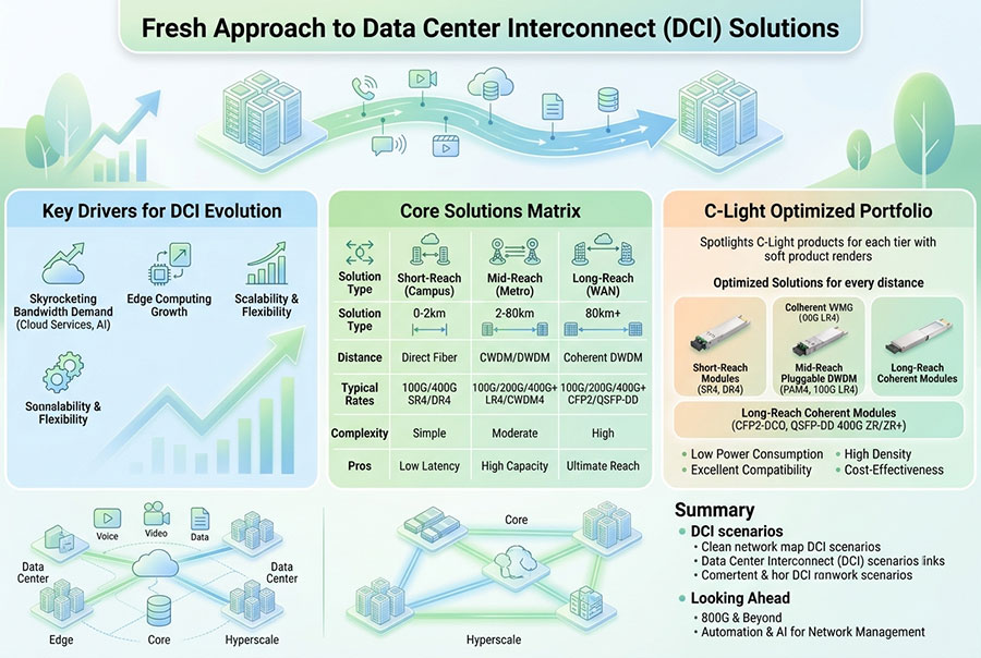
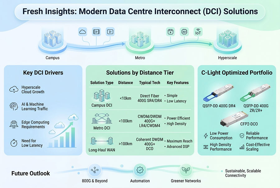
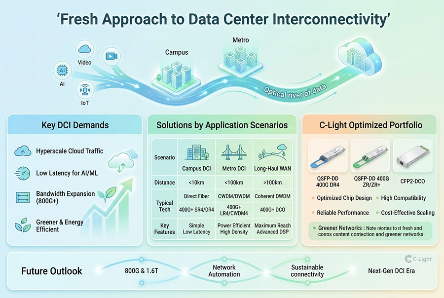
Campus interconnect: Links separate buildings or data-center halls across a campus using direct fiber, high-speed Ethernet optics or dedicated optical transport.
Metro and regional DCI: Connects geographically separated facilities through dark fiber, DWDM systems, coherent pluggables or managed wavelength services.
For short campus connections, direct optical Ethernet interfaces may be sufficient when the fiber plant and reach support the required data rate. For longer metro and regional paths, coherent optical transmission and DWDM systems can increase capacity per fiber pair and support multiple wavelengths over a shared optical infrastructure.
ROADM-based optical networks can provide flexible wavelength routing across multi-site transport topologies. This allows operators to establish or modify optical paths without rebuilding the physical fiber network for every new connection. The appropriate design depends on fiber availability, route diversity, traffic growth and the operational model of the network.
4. High-Speed Optical Transceivers for AI Interconnects
Optical transceiver selection should follow the network's actual link requirements. Port speed alone does not determine whether a module is suitable. Engineers must also consider optical reach, fiber type, connector configuration, host interface, power consumption, thermal limits and interoperability with the switching platform.
| Optical Category | Typical Network Role | Key Design Considerations |
|---|---|---|
| 400G Ethernet Optics | Existing high-bandwidth data-center fabrics and selected campus links | Port density, fiber reach, lane architecture and migration requirements |
| 800G SR8 / DR8 | High-density connections within data centers and short-reach infrastructure | Multimode or single-mode fiber, MPO interface and optical lane configuration |
| 800G 2FR4 | Short-reach single-mode links between compatible high-speed interfaces | 2 km optical reach, duplex LC connectivity and platform compatibility |
| 800G Coherent DCO | Metro and regional optical transport, depending on the selected implementation | Modulation, OSNR, fiber route, line-system compatibility and reach |
| 1.6T OSFP-RHS | Next-generation high-density AI data-center interconnects | 8 × 200G architecture, host interface, thermal design and optical reach |
For short-reach connections, parallel optical interfaces such as SR8 and DR8 can provide high port bandwidth within a facility. Duplex optical designs such as 2FR4 use a different fiber and connector arrangement. These interfaces are not interchangeable simply because they share the same aggregate data rate.
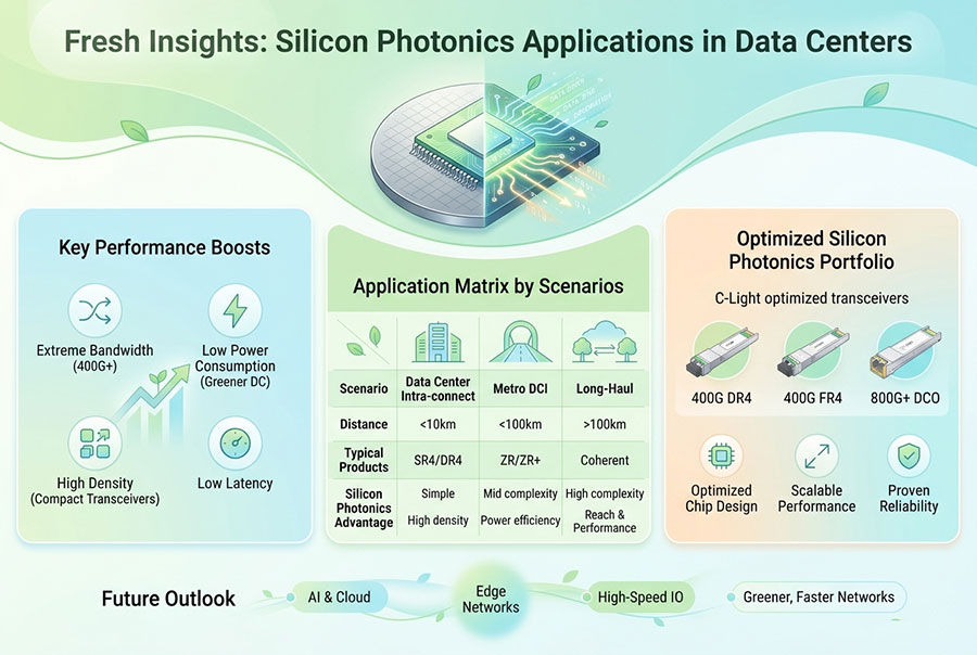
For longer distances, coherent optical modules provide a different transmission approach. Coherent DSP, advanced modulation and wavelength tuning support high-capacity transmission over engineered optical paths. The achievable distance depends on the module configuration, line system, fiber characteristics, optical signal-to-noise ratio and required performance margin.
5. Coherent DWDM Transport for Metro and Regional AI Connectivity
As participating AI facilities become geographically separated, the interconnect must operate beyond the reach of conventional short-reach data-center optics. Coherent DWDM transport is a key option for extending high-capacity connectivity across metro and regional networks.
A coherent transceiver uses a local oscillator and digital signal processing to recover information encoded in the amplitude and phase of an optical signal. This approach supports advanced modulation formats and enables higher spectral efficiency than conventional intensity-modulation direct-detection interfaces in suitable network conditions.
DWDM combines multiple optical wavelengths on a fiber pair. Each wavelength can carry a high-capacity data stream, allowing network operators to expand aggregate transport capacity without installing a separate fiber pair for every service.
Pluggable coherent DCO modules integrate coherent transmission functions into compact transceiver form factors. Depending on the module and host platform, they can connect directly to compatible routers or transport equipment. A separate optical line system may still be required for amplification, wavelength multiplexing, filtering and long-distance transmission.
C-LIGHT DWDM DCO Coherent Transceiver
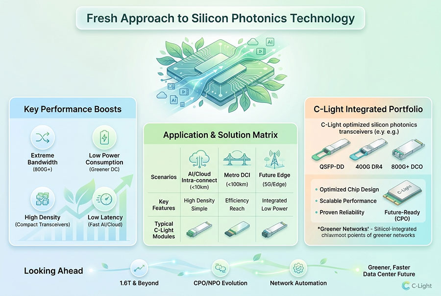
The C-LIGHT DWDM DCO portfolio covers coherent transceiver options from 100G to 800G, with QSFP28, CFP2, QSFP-DD and OSFP form factors. It is relevant to metro and regional DCI designs where coherent transmission and DWDM wavelength management are required.
Final selection should be based on the exact data rate, modulation mode, host interface, optical budget, line-system configuration and required transmission distance.
Coherent transport does not remove the need for packet-layer engineering. Optical wavelengths provide physical capacity, but routing, traffic classification, congestion control and workload placement determine how efficiently AI training traffic uses the available bandwidth.
6. Latency, Jitter and Packet Loss Across Distributed GPU Clusters
Bandwidth is only one part of multi-data-center training performance. The network must also maintain predictable behavior under sustained load. In tightly synchronized training jobs, delayed or missing communication can cause some workers to wait for others, reducing effective accelerator utilization.
Propagation delay: Fiber distance imposes a physical latency floor. Optical transmission cannot eliminate the propagation time associated with a long route. Additional latency is introduced by routers, switches, transport equipment, buffering and packet processing.
Queueing and congestion: Oversubscribed links and uneven traffic distribution can create queue buildup. During synchronized communication bursts, congestion may affect multiple flows at the same time. Capacity planning and traffic engineering must therefore account for peak behavior, not only average utilization.
Packet loss: Loss can trigger retransmissions or recovery mechanisms in the transport stack. For RDMA-based environments, congestion control, queue management and loss-handling behavior require particular attention because the backend fabric may have strict performance expectations.
Jitter: Variation in packet delay can make communication completion less predictable. Stable paths, consistent queueing behavior and appropriate quality-of-service policies help reduce performance variation.
Engineering priority: A high-capacity optical path is not automatically a low-latency AI network. Fiber route length, switching depth, oversubscription, packet scheduling and congestion behavior must be evaluated together.
7. Redundancy and Optical Path Protection
Multi-site AI training introduces additional failure domains. A fiber cut, optical equipment fault, power interruption or routing failure can affect communication between entire compute clusters. If the training framework depends on continuous synchronization across sites, transport interruption can have a wider impact than the failure of an isolated application connection.
Network resilience should be designed across both optical and packet layers. Important measures include:
Physically diverse fiber routes: Separate pathways reduce the risk that a single excavation event or cable fault interrupts all inter-site connectivity.
Redundant optical equipment: Protection at the transponder, amplifier and line-system levels can reduce the impact of equipment failures.
Packet-layer fast reroute: Routing protection can redirect traffic when a network path or node becomes unavailable.
Capacity on alternate paths: Backup routes need sufficient reserved capacity to carry critical traffic after a failure.
Coordinated recovery: Optical protection, routing convergence and application-level recovery should be tested as one operational process.
Protection behavior must be measured rather than assumed. Restoration time, packet interruption, path asymmetry and post-failure congestion can all affect distributed training. A backup route that is physically available but heavily loaded may not provide the required service quality.
8. Fiber Infrastructure and Optical Link Qualification
High-speed DCI performance depends on the physical fiber plant as much as the transceiver. Connector contamination, excessive insertion loss, reflection, splice loss, fiber bending and poor connector mating can reduce the available optical margin. At higher data rates, marginal physical-layer conditions can become more difficult to diagnose because the system may have less tolerance for additional penalties.
Before commissioning an inter-data-center link, engineers should verify the following:
Fiber type and route length are compatible with the selected optical interface.
Connector type, polarity and fiber mapping match the transceiver configuration.
Insertion loss and optical return loss meet the link design requirements.
Wavelength allocation and channel spacing are compatible with the DWDM line system.
Optical power levels remain within the transmitter and receiver operating ranges.
End-to-end throughput, latency, jitter and packet-loss performance meet the service target.
Environmental conditions and equipment cooling remain within the specified operating limits.
For coherent links, qualification should also include optical signal-to-noise ratio, pre-FEC and post-FEC performance where available, polarization-related impairments and channel behavior across the intended operating range. Acceptance testing should use the actual fiber route and line-system configuration rather than relying exclusively on laboratory specifications.
9. C-LIGHT Optical Connectivity for High-Density AI Networks
Multi-data-center AI infrastructure requires optical products across several distance and bandwidth categories. Short-reach transceivers support connections within and between nearby facilities, while coherent DCO modules address longer transport paths. A portfolio covering multiple form factors and transmission technologies can support staged network upgrades as compute capacity expands.
800G OSFP Optical Transceiver
The C-LIGHT 800G OSFP portfolio includes SR8, DR8 and 2×FR4 configurations, alongside coherent options. Listed short-reach configurations include SR8 at 100m, DR8 at 500m and 2×FR4 at 2km. These options address different optical link requirements within high-density data-center and campus networks.
1.6T OSFP-RHS Optical Transceiver
The C-LIGHT 1.6T OSFP-RHS portfolio includes 1.6T configurations based on 8 × 200G signaling. Listed options include 2×DR4 at 500m and 2×FR4 at 2km. The reduced-height heatsink design is intended for high-density systems with demanding thermal integration requirements.
DWDM DCO Coherent Transceivers
For metro and regional transport, the C-LIGHT DWDM DCO product family provides coherent options across multiple data rates and pluggable form factors. These modules can be evaluated for DCI applications where wavelength-based optical transport is part of the network architecture.
Product selection should be finalized against the host equipment, optical line system, fiber characteristics and required service distance. Data rate and form factor alone do not establish interoperability. C-LIGHT can support optical transceiver selection and connectivity planning based on the target network configuration.
10. Capacity Planning for Multi-Site AI Expansion
Inter-data-center bandwidth should be planned around the training workload and its communication schedule. A network designed only around the initial GPU count may become a bottleneck as additional accelerators, parallelism groups or training jobs are introduced.
Capacity planning should consider the following variables:
Aggregate accelerator bandwidth: Estimate the communication demand generated by the participating GPU groups and their parallelism strategy.
Collective communication frequency: Identify how often synchronization operations occur and whether they create concentrated traffic bursts.
Concurrent workloads: Account for multiple training jobs, inference services, storage replication and model distribution operating simultaneously.
Oversubscription: Evaluate the ratio between aggregate endpoint capacity and available inter-site bandwidth.
Failure capacity: Include the additional bandwidth required when traffic moves to alternate paths during a failure.
Future migration: Consider 400G, 800G and 1.6T interface roadmaps, along with the ability to add wavelengths or upgrade line systems.
It is also important to distinguish interface rate from usable application throughput. Protocol overhead, framing, FEC, packet processing and congestion can reduce effective throughput. Network validation should therefore measure application-relevant performance under representative traffic conditions.
11. Operational Monitoring and End-to-End Performance Management
Multi-data-center AI networks need monitoring across optical, packet and application layers. A transceiver may report normal optical power while the end-to-end service still experiences congestion, packet loss or excessive latency. Conversely, a training slowdown may originate from workload imbalance rather than a physical optical fault.
| Monitoring Layer | Key Metrics | Operational Purpose |
|---|---|---|
| Optical Transceiver | Tx power, Rx power, temperature, supply voltage and laser bias where supported | Identify module-level alarms and optical degradation |
| Optical Transport | OSNR, channel power, pre-FEC and post-FEC indicators where available | Evaluate wavelength and line-system performance |
| Packet Network | Throughput, latency, jitter, packet drops, congestion and interface errors | Track end-to-end network service quality |
| AI Workload | GPU utilization, collective communication time and training-step duration | Correlate network behavior with training efficiency |
Digital diagnostics monitoring provides useful transceiver-level information, but it does not replace packet testing or optical line-system measurements. Correlating telemetry from all three layers helps operators identify whether a performance issue originates in the optical path, packet fabric or AI application.
12. Building a Scalable Optical Foundation for Distributed AI
Multi-data-center AI training changes the role of DCI from a general connectivity service into a performance-critical component of distributed compute infrastructure. The optical network must support high aggregate bandwidth while maintaining predictable transmission behavior across campus, metro and regional distances.
Short-reach 800G and 1.6T transceivers support increasing bandwidth density inside and between nearby facilities. Coherent DCO modules and DWDM transport extend high-capacity connectivity across longer routes. Meanwhile, fiber diversity, optical protection, packet-layer traffic engineering and end-to-end monitoring provide the operational foundation for reliable distributed training.
Conclusion: Successful scale-across AI infrastructure depends on the coordination of optical transport, packet networking and compute scheduling. Higher interface speeds are important, but they must be supported by qualified fiber routes, appropriate optical architectures, sufficient failure capacity and measurable end-to-end performance. A carefully engineered optical DCI foundation allows multiple data centers to operate as a more scalable and coordinated AI training environment.
For optical transceiver selection, DCI connectivity planning and high-speed network requirements, Contact C-LIGHT.
 >

 >
 >
 >
 >
 >
 >
 >