TEL:+86 132 6656 7067




MPO and MTP are widely used multifiber connector technologies for high-density optical networks. They are especially common in data centers and high-speed optical links where multiple fibers must be connected through a compact interface.
MPO is a standardized family of multifiber push-on connectors, while MTP is a trademarked enhanced version of MPO developed by US Conec. Because MTP follows the MPO interface concept, MTP connectors are generally MPO-compatible when the corresponding mechanical, optical, pinning, and polarity requirements are satisfied.
The difference between MPO and MTP is therefore not simply that one is a connector type and the other is a completely different technology. MTP is an enhanced MPO connector design intended to improve mechanical performance, optical performance, and usability in high-density fiber systems.
1. What Is an MPO Connector?
MPO stands for Multi-Fiber Push On.
It is a multifiber connector that can terminate multiple optical fibers in a single connector body. Depending on the design, an MPO connector can support different fiber counts, including common 8-, 12-, 16-, 24-, and higher-fiber configurations.
MPO connectors allow multiple optical channels to be connected simultaneously, making them suitable for parallel optical applications and high-density structured cabling.
2. What Is an MTP Connector?
MTP is a trademark of US Conec for its enhanced MPO connector family.
MTP connectors maintain the general MPO interface concept while incorporating design improvements intended to provide better mechanical alignment, lower insertion loss, better return-loss performance, improved end-face control, and easier handling.
MTP is therefore best understood as an enhanced MPO connector rather than an entirely separate connector standard.
3. MPO vs MTP: Basic Difference
| Parameter | MPO | MTP |
|---|---|---|
| Meaning | Multi-Fiber Push On connector family | Enhanced MPO connector family from US Conec |
| Multifiber connection | Yes | Yes |
| Typical fiber counts | 8, 12, 16, 24 and others | 8, 12, 16, 24 and others |
| Basic interface concept | Multifiber push-on | Enhanced multifiber push-on |
| Alignment pins | Yes, depending on connector design | Yes |
| Mechanical design | Varies by manufacturer | Enhanced design |
| Interoperability | Depends on exact specification | Generally MPO-compatible when specifications match |
| Typical use | High-density fiber connections | High-density performance-oriented fiber connections |
4. Is MTP the Same as MPO?
No, but they are closely related.
MPO is the generic connector family and standardized interface concept. MTP is a specific enhanced implementation of the MPO connector developed by US Conec.
This means that an MTP connector belongs to the broader MPO connector ecosystem, but not every MPO connector is an MTP connector.
5. Why Are MPO and MTP Often Called the Same?
In real-world data center cabling, the terms are often used interchangeably because both are designed for multifiber connections and can share similar physical form factors.
For example, a 12-fiber MTP trunk cable may be described in a project simply as a 12-fiber MPO trunk.
However, engineering specifications should identify the exact connector construction and performance instead of relying only on the general MPO name.
6. MPO Connector Structure
A typical MPO connector includes:
Multifiber ferrule
Guide pins or pin receptacles
Connector housing
Latch mechanism
Fiber array
The ferrule holds multiple fiber ends in a precise linear or multi-row arrangement.
7. MTP Connector Structure
MTP connectors use the same basic multifiber ferrule concept but incorporate enhanced mechanical and optical design features.
Depending on the connector version, these features can include improved ferrule alignment, spring mechanisms, removable housing designs, and improved control of fiber-end-face positioning.
8. Ferrule Alignment
Multifiber connectors require highly accurate alignment because several fiber cores must line up simultaneously.
A small alignment error that affects one fiber can affect the optical performance of an individual lane.
As fiber counts and data rates increase, maintaining stable mechanical alignment becomes increasingly important.
9. MTP Alignment Improvements
One of the purposes of the enhanced MTP design is to improve alignment performance and mechanical stability.
This is particularly useful in high-density environments where connectors are repeatedly connected, disconnected, handled, and exposed to mechanical stress.
10. Insertion Loss
Insertion loss describes the optical power lost as light passes through the connector.
For a multifiber connector, insertion loss must be considered for every optical channel.
A high insertion-loss connector can reduce the available optical budget, which becomes especially important for high-speed links with limited optical margin.
11. MPO vs MTP Insertion Loss
| Characteristic | MPO | MTP |
|---|---|---|
| Insertion loss | Depends on connector grade and manufacturer | Designed for low-loss performance |
| Per-fiber variation | Depends on connector quality | Controlled by connector design and manufacturing |
| High-density application | Yes | Yes |
| Impact on optical budget | Important | Important |
The correct comparison should always use the actual connector specification rather than assuming every MPO or every MTP connector has the same insertion loss.
12. Return Loss
Return loss measures the amount of optical power reflected back toward the transmitter.
Multifiber connector end-face quality, alignment, physical contact, contamination, and fiber geometry can all affect return-loss performance.
Higher return loss generally indicates less reflected optical power.
13. MPO vs MTP Return Loss
Both MPO and MTP systems are designed to provide controlled optical interfaces, but actual return-loss performance depends on the exact connector design, fiber type, end-face condition, and mating configuration.
MTP's enhanced connector design is intended to provide highly controlled optical contact and alignment.
14. Connector End-Face Quality
Multifiber connector performance depends heavily on the condition of the fiber end face.
Dust, oil, scratches, pits, contamination, or damaged fiber surfaces can cause increased insertion loss and reflection.
This is particularly important for MPO and MTP connectors because many fiber cores are exposed on the same end face.
15. Cleaning MPO and MTP Connectors
Proper cleaning is essential before mating a multifiber connector.
Because one connector may contain many fibers, a single contaminated connector can affect multiple optical channels simultaneously.
Connector inspection and appropriate cleaning procedures should therefore be part of normal high-density fiber maintenance.
16. MPO and MTP Gender
MPO and MTP connectors use male and female configurations.
A male connector contains guide pins, while a female connector does not contain guide pins and is designed to mate with the corresponding pinned connector.
The exact connector assembly must therefore be checked before two multifiber connectors are connected.
17. Why Guide Pins Matter
Guide pins are responsible for accurately aligning the multifiber ferrules.
Because several fiber cores must align simultaneously, the mechanical accuracy of the guide-pin system is extremely important.
Damaged, bent, contaminated, or mismatched guide pins can affect multiple optical channels.
18. MPO and MTP Polarity
Polarity defines how each optical fiber in one connector corresponds to the correct fiber at the opposite end.
In a multi-fiber system, correct polarity is essential because one connector can contain many transmit and receive channels.
An incorrect polarity scheme can prevent the optical link from establishing even when the optical components themselves are functioning correctly.
19. Type A Polarity
Type A uses a straight-through fiber mapping.
Fiber position 1 connects to fiber position 1, fiber position 2 connects to fiber position 2, and so on.
This arrangement is commonly used as part of structured trunk-cabling systems.
20. Type B Polarity
Type B uses a reversed fiber mapping.
The first fiber position at one end connects to the last corresponding position at the opposite end.
This configuration is commonly associated with parallel optical transceiver links where transmit and receive positions need to be crossed through the cabling system.
21. Type C Polarity
Type C uses pairwise fiber-position reversal.
For example, the first and second fibers form a reversed pair, followed by the third and fourth fibers, and so on.
This method can be useful for certain duplex structured-cabling architectures.
22. MPO/MTP Polarity Comparison
| Polarity Type | Basic Mapping | Typical Use |
|---|---|---|
| Type A | Straight-through | Structured trunk systems |
| Type B | Complete fiber reversal | Parallel optics and selected high-speed links |
| Type C | Pairwise reversal | Selected duplex structured cabling |
23. Polarity Is More Important at Higher Speeds
A 12-fiber connector may carry multiple independent optical lanes.
At 40G, 100G, 200G, 400G, and 800G, incorrect polarity can result in several transmit and receive channels being connected to the wrong positions.
Polarity planning should therefore be completed before installing the trunk cables, harnesses, cassettes, and transceivers.
24. MPO/MTP and Parallel Optics
MPO and MTP connectors are strongly associated with parallel optical transmission.
For example, a 40G SR4 link can use four optical lanes for transmission and four for reception.
Later generations of high-speed transceivers can use even more optical lanes or different wavelength architectures.
25. 40G MPO/MTP Applications
40GBASE-SR4 is a classic application for multimode MPO/MTP connectivity.
The transceiver uses multiple optical lanes and therefore requires a multi-fiber interface instead of a conventional duplex LC connection.
This helped establish MPO/MTP as an important data center cabling technology.
26. 100G MPO/MTP Applications
100G SR4 and other parallel-lane architectures can use MPO/MTP connectors for multimode or single-mode fiber depending on the specific optical design.
This allows several optical channels to be connected using one compact connector.
27. 400G MPO/MTP Applications
400G optical modules can use different connector architectures depending on the PMD.
Parallel single-mode and multimode designs can use MPO/MTP interfaces, while WDM-based designs may use duplex LC.
Therefore, 400G does not automatically mean MPO or MTP.
28. 800G MPO/MTP Applications
800G transceiver architectures can also use MPO/MTP interfaces for suitable parallel optical designs.
However, WDM-based 800G modules may use duplex LC or other optical interfaces.
The connector must therefore be selected according to the optical architecture.
29. Fiber Count and High-Speed Optics
MPO/MTP connectors can support multiple fiber counts and configurations.
Common data center applications use 8-, 12-, and 16-fiber interfaces, while higher-density systems can use more fibers.
The required fiber count depends on the number of optical lanes, transmit/receive arrangement, and PMD architecture.
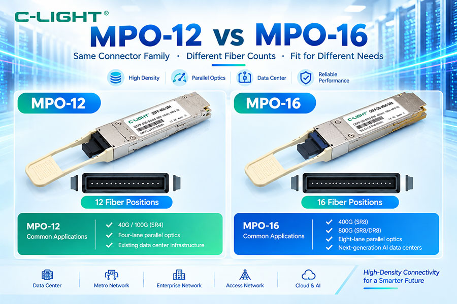
30. 8-Fiber vs 12-Fiber vs 16-Fiber MPO/MTP
| Configuration | Typical Purpose |
|---|---|
| 8-fiber | Parallel optical systems using four transmit and four receive fibers |
| 12-fiber | Legacy and structured high-density cabling |
| 16-fiber | Higher-density parallel optical systems and next-generation architectures |
| 24-fiber | High-density structured fiber distribution |
31. MPO vs MTP Ferrule
The ferrule is one of the most important components in a multifiber connector.
It holds multiple fiber ends in precise alignment.
MTP uses enhanced ferrule and mechanical design features intended to improve fiber alignment and connector performance.
32. MTP Removable Housing
Some MTP connector designs use removable housings.
This can make polarity changes, connector reconfiguration, and field handling more convenient without replacing the entire fiber assembly.
The exact available features depend on the MTP connector version.
33. MTP Floating Ferrule Concept
Enhanced MTP designs can use a floating-ferrule mechanism to help maintain better physical alignment during mating.
This can reduce the effect of mechanical tolerances between connector components and improve consistency across repeated mating cycles.
34. Spring Design
Multifiber connectors require controlled spring pressure to maintain physical contact across multiple fiber positions.
MTP connector designs include spring-related improvements intended to provide more consistent pressure and mechanical performance.
35. MPO vs MTP Mechanical Performance
| Mechanical Factor | MPO | MTP |
|---|---|---|
| Multifiber ferrule | Yes | Yes |
| Guide-pin alignment | Yes | Yes |
| Enhanced alignment design | Depends on manufacturer | Yes |
| Removable housing | Depends on design | Available in selected designs |
| Mechanical optimization | Varies | Enhanced design focus |
36. MPO and MTP Compatibility
MPO and MTP connectors can often mate when their mechanical and optical specifications are compatible.
However, compatibility should not be assumed simply because both connectors are called MPO or MTP.
Fiber count, gender, guide-pin configuration, key orientation, polishing, fiber type, and connector geometry must all match.
37. Can MTP Connect to MPO?
Yes, compatible MTP and MPO connectors can be mated because MTP is part of the MPO connector ecosystem.
However, both connectors must have matching mechanical specifications and appropriate male/female configurations.
38. Can MPO Connect to MTP?
Yes, the same compatibility principle applies in the opposite direction.
The connector pair must have compatible ferrules, guide pins, gender, key orientation, and other relevant mechanical characteristics.
39. Can Any MPO and MTP Cable Be Mixed?
No.
The terms MPO and MTP describe the connector family, not the complete cable configuration.
A compatible system also requires matching fiber type, fiber count, polarity, gender, connector key orientation, and optical performance.
40. MPO vs MTP Cable
The connector alone does not define a complete fiber-optic cable.
An MPO or MTP cable can be manufactured using:
Multimode fiber
Single-mode fiber
Different fiber counts
Different polarity configurations
Different connector genders
Therefore, "MPO cable" and "MTP cable" should be specified more precisely when ordering or designing a network.
41. MPO/MTP Multimode Cables
Multimode MPO/MTP cables are widely used with 850 nm VCSEL-based optical modules.
Common fiber categories include OM3 and OM4, with OM5 used in selected wideband multimode applications.
42. MPO/MTP Single-Mode Cables
Single-mode MPO/MTP cables are used with parallel single-mode transceivers and other high-density single-mode architectures.
Examples include selected 100G, 200G, 400G, and 800G parallel optical solutions.
43. Fiber Type Still Matters
Two cables can both use MTP connectors but have completely different optical properties.
For example, one may contain OM4 multimode fiber and another may contain OS2 single-mode fiber.
The connector name alone is therefore insufficient for selecting an optical cable.
44. MPO/MTP and OS2
OS2 single-mode fiber can be terminated with MPO/MTP connectors for parallel single-mode optical systems.
This allows multiple single-mode channels to be connected in a compact interface.
45. MPO/MTP and OM4
OM4 is one of the most common multimode fiber categories used with MPO/MTP data center cabling.
It is especially suitable for high-speed 850 nm VCSEL-based parallel optical systems.
46. MPO/MTP and OM5
OM5 can also use MPO/MTP connectors.
Its wideband multimode characteristics become particularly useful in architectures that use multiple short wavelengths such as SWDM.
47. MPO/MTP and SWDM
SWDM uses multiple short wavelengths over multimode fiber.
MPO/MTP can provide the physical multi-fiber connection for an SWDM system, but the connector itself does not perform wavelength multiplexing.
The optical transceiver and internal optical components provide the wavelength-division function.
48. MPO/MTP and WDM
WDM and MPO/MTP solve different problems.
WDM increases capacity by combining multiple wavelengths.
MPO/MTP increases connection density by placing multiple fibers into one physical connector.
A system can use either technology independently or combine them depending on the architecture.
49. MPO/MTP and LC
LC and MPO/MTP serve different connectivity purposes.
LC is generally used for duplex fiber connections, while MPO/MTP is designed for multiple fibers in one connector.
| Connector | Typical Use |
|---|---|
| LC | Duplex single-mode or multimode connections |
| MPO/MTP | High-density multifiber connections |
50. Why MPO/MTP Is Important for Data Centers
Data centers require a large number of optical connections in a limited physical space.
MPO/MTP reduces connector count and cable bulk by allowing several optical fibers to be terminated in a single connector.
This improves port density and simplifies high-density structured cabling.
51. Cable Management
MPO/MTP trunk cables can significantly reduce the amount of physical cabling compared with using many individual duplex patch cords.
However, high-density cabling also requires careful management of bend radius, polarity, labeling, cassette orientation, and connector accessibility.
52. MPO/MTP Polarity Planning
A structured MPO/MTP network should define its polarity architecture before installation.
The design should identify:
Trunk polarity
Harness polarity
Cassette polarity
Transceiver fiber mapping
Connector key orientation
This prevents accidental fiber reversal and simplifies troubleshooting.
53. Key Orientation
MPO/MTP connectors use keyed housings to control the orientation of the connector during mating.
Key-up and key-down configurations affect fiber mapping and therefore must be considered as part of the polarity design.
54. MPO/MTP Pin Configuration
Because MPO/MTP connectors require precise ferrule alignment, pinned and unpinned connector configurations must be matched correctly.
A male connector normally mates with a female connector so that the guide pins provide the required ferrule alignment.
55. Incorrect Gender
Two connectors with incompatible gender configurations cannot be properly mated.
This is a common issue when combining cables, adapters, cassettes, and transceiver harnesses from different sources.
56. Incorrect Polarity
Even when two MPO/MTP connectors can physically mate, the optical link can still fail if the fiber mapping is incorrect.
Physical compatibility and optical polarity compatibility are therefore separate requirements.
57. Testing MPO/MTP Links
MPO/MTP links should be tested for optical insertion loss and, where required, return loss.
Because multiple optical channels exist within one connector, testing should verify each relevant fiber position rather than treating the entire connector as a single optical channel.
58. MPO/MTP Connector Inspection
Connector inspection is particularly important for multifiber connectors.
A single contaminated end face can affect multiple fibers at the same time.
Inspection should therefore be performed before mating and after any event that could contaminate or damage the connector.
59. MPO/MTP and High-Speed Optical Modules
High-speed optical modules place stricter requirements on connector performance because optical budgets become smaller and lane rates increase.
A connector that performs adequately in a low-speed application may not provide sufficient margin in a higher-speed link.
60. MPO/MTP and 400G/800G Networks
400G and 800G networks can use very high numbers of optical lanes.
MPO/MTP allows these lanes to be connected through compact multifiber interfaces where supported by the optical architecture.
However, the module type must be checked first because many WDM-based 400G and 800G transceivers use duplex LC rather than MPO/MTP.
61. MPO vs MTP for High-Density Networking
| Factor | MPO | MTP |
|---|---|---|
| High fiber density | Yes | Yes |
| Parallel optics | Yes | Yes |
| Data center use | Common | Common |
| Enhanced mechanical design | Depends on manufacturer | Yes |
| Optical performance | Depends on connector grade | Enhanced design focus |
| Interoperability | Specification-dependent | MPO ecosystem compatibility when specifications match |
62. MPO vs MTP: Performance Is Not Determined by Name Alone
The terms MPO and MTP do not provide the complete optical performance specification.
When comparing cables, also check:
Insertion loss
Return loss
Fiber type
Fiber count
Polarity
Gender
Connector grade
Operating wavelength
63. MPO vs MTP for 100G
For 100G parallel optical links, both MPO and MTP can be used when their connector configurations meet the transceiver requirements.
OM3 and OM4 multimode links may use MPO/MTP for 850 nm SR architectures, while single-mode parallel solutions can use MPO/MTP with OS2 fiber.
64. MPO vs MTP for 400G
For 400G, the connector depends strongly on the PMD.
DR4 and selected SR architectures can use multifiber connectors, while FR4 and LR4-family architectures commonly use duplex LC because the optical signal is multiplexed into multiple wavelengths over two fibers.
65. MPO vs MTP for 800G
800G has an even wider range of optical architectures.
SR and parallel-lane designs may use MPO/MTP, while 2FR4 and other WDM architectures can use duplex LC.
Therefore, MPO/MTP selection must always follow the transceiver architecture.
66. MPO/MTP and Breakout Cables
Breakout cables convert a multifiber connector into multiple individual fiber connectors.
For example, an MPO/MTP trunk can be broken out into multiple LC duplex connections.
This provides a transition between high-density backbone cabling and conventional duplex optical interfaces.
67. MPO/MTP Harness Cables
Harness cables include a multifiber connector on one side and individual connectors on the other side.
They are commonly used to connect high-density switch ports to lower-density patching or transceiver interfaces.
68. MPO/MTP Cassettes
MPO/MTP cassettes provide a structured transition between multifiber trunks and conventional duplex fiber ports.
This can simplify data center cabling by moving complex fiber mapping into a standardized modular component.
69. MPO/MTP Trunk Cables
MPO/MTP trunk cables provide direct multifiber connectivity between patch panels, cassettes, and other high-density fiber systems.
The trunk design reduces the number of individual cables required and improves cable-density management.
70. MPO vs MTP: Which One to Choose?
The selection should begin with the optical system rather than the connector brand.
First determine the transceiver interface and fiber type. Then define the required fiber count, polarity, gender, insertion loss, return loss, and cable length.
MTP can be selected when the enhanced connector design and specified performance are required. Standard MPO connectors can also be suitable when the required mechanical and optical specifications are met.
71. Practical MPO/MTP Selection Process
Step 1: Identify the transceiver interface.
Step 2: Determine the fiber type: OM3, OM4, OM5, or OS2.
Step 3: Determine the required fiber count.
Step 4: Confirm connector gender.
Step 5: Confirm key orientation.
Step 6: Select the correct polarity.
Step 7: Check insertion loss and return loss.
Step 8: Confirm compatibility with the complete cabling system.
72. MPO vs MTP: Complete Comparison
| Parameter | MPO | MTP |
|---|---|---|
| Definition | Multifiber Push On connector family | Enhanced MPO connector family |
| Brand relationship | Generic connector terminology | US Conec trademark |
| Multifiber support | Yes | Yes |
| Typical fiber counts | 8 / 12 / 16 / 24 and others | 8 / 12 / 16 / 24 and others |
| Male / female configuration | Yes | Yes |
| Polarity support | Type A / B / C systems | Type A / B / C systems |
| Insertion loss | Specification-dependent | Specification-dependent, enhanced connector designs available |
| Mechanical alignment | Specification-dependent | Enhanced alignment design |
| Data center use | Common | Common |
| Parallel optics | Yes | Yes |
| High-density cabling | Yes | Yes |
73. Key Difference in One Sentence
The simplest way to remember the relationship is:
MPO is the broader multifiber connector family, while MTP is an enhanced MPO connector design.
74. Conclusion
MPO and MTP are closely related multifiber connector technologies used extensively in high-density optical networks.
MPO refers to the broader Multi-Fiber Push On connector family, while MTP is a trademarked enhanced MPO connector developed by US Conec. MTP maintains the general MPO interface concept while adding mechanical and optical design improvements intended to provide consistent alignment and high-performance connectivity.
In practical data center deployments, the difference between MPO and MTP is only one part of the overall cabling design. Fiber type, fiber count, polarity, connector gender, key orientation, insertion loss, return loss, and transceiver interface are equally important.
For 100G, 400G, 800G, and future high-density optical networks, MPO/MTP connectors provide an efficient way to manage multiple optical lanes in a compact physical interface. However, not every high-speed transceiver uses MPO/MTP. WDM-based optical modules may use duplex LC instead, so connector selection should always follow the specific optical architecture.
For C-LIGHT optical transceivers and fiber cabling systems, the correct approach is to match the transceiver, fiber type, connector, polarity, fiber count, and optical performance as one complete link rather than selecting MPO or MTP based on the connector name alone.
 >
>

 >
>
 >
>
 >
>
 >
>
 >
>
 >
>
 >
>