TEL:+86 132 6656 7067




MPO-8, MPO-12, and MPO-16 are multifiber connector configurations designed for high-density optical connectivity. The main difference is the number of fiber positions provided by the connector: eight, twelve, or sixteen fibers.
The fiber count, however, does not directly determine the Ethernet data rate. An MPO connector is only the physical optical interface. The number of active fibers, transmit and receive mapping, polarity, wavelength architecture, and transceiver design determine how the connector is actually used.
This is particularly important for 400G and 800G optical networks. A 400G DR4 transceiver may use an 8-fiber configuration or a 12-fiber connector with unused positions, while a 400G SR8 architecture uses 16 fibers for eight transmit and eight receive channels. Therefore, MPO-8, MPO-12, and MPO-16 should be selected according to the complete optical architecture rather than the connector name alone.
1. What Is MPO-8?
MPO-8 refers to an MPO connector configuration containing eight fiber positions.
A common arrangement is 1×8, with eight fibers positioned in a single row. Another configuration can be 4+4, where four fibers are used for transmission and four fibers are used for reception.
MPO-8 is particularly suitable for parallel optical architectures that require four transmit and four receive channels.
2. What Is MPO-12?
MPO-12 contains twelve fiber positions, usually arranged as a single row of twelve fibers.
It has been widely adopted in structured data center cabling and parallel optical systems.
One important feature of MPO-12 is that not every application necessarily uses all twelve fibers. Some 8-fiber optical architectures use an MPO-12 connector with four fiber positions left unused.
3. What Is MPO-16?
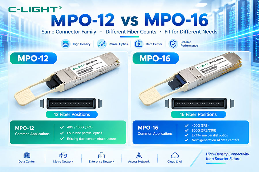
MPO-16 contains sixteen fiber positions and is commonly arranged as a single row of sixteen fibers.
It provides a higher fiber density than MPO-8 and MPO-12 and is particularly useful for optical architectures that require eight transmit fibers and eight receive fibers.
MPO-16 is increasingly relevant to high-speed parallel optical systems that use more optical lanes.
4. MPO-8 vs MPO-12 vs MPO-16
| Parameter | MPO-8 | MPO-12 | MPO-16 |
|---|---|---|---|
| Fiber positions | 8 | 12 | 16 |
| Common arrangement | 1×8 or 4+4 | 1×12 | 1×16 |
| Common use | 4-lane parallel optics | Structured cabling and 4-lane systems | 8-lane parallel optics |
| Fiber density | Low | Medium | High |
| Typical parallel architecture | 4 TX + 4 RX | 4 TX + 4 RX with spare positions in some systems | 8 TX + 8 RX |
| Typical high-speed use | Selected 400G architectures | 400G and structured cabling | 400G SR8 and higher-lane architectures |
5. Fiber Count Does Not Equal Data Rate
An MPO-8 connector does not automatically mean 400G, and an MPO-16 connector does not automatically mean 800G.
The connector only determines how many physical fiber positions are available.
The actual bandwidth depends on the number of active optical lanes and the data rate carried by each lane.
6. Active Fibers vs Total Fibers
This distinction is essential for understanding MPO-12 systems.
An MPO-12 connector contains twelve fiber positions, but an optical system may use only eight of them.
For example:
4 TX + 4 RX + 4 unused = 12-fiber MPO
The four unused positions remain physically available but are not part of the active optical link.
7. Why MPO-12 Can Have Unused Fibers
MPO-12 became widely established in structured cabling before some newer optical architectures required different fiber counts.
Using a 12-fiber trunk for an 8-fiber parallel optical architecture can allow compatibility with existing data center cabling infrastructure.
Transition modules and breakout assemblies can also be designed around the 12-fiber ecosystem.
8. Why MPO-8 Uses Exactly Eight Fibers
MPO-8 can provide a compact physical interface for eight active optical channels.
For a conventional parallel architecture, these can be arranged as:
TX1 + TX2 + TX3 + TX4 + RX1 + RX2 + RX3 + RX4
This makes MPO-8 efficient for systems requiring four transmit and four receive optical lanes.
9. Why MPO-16 Uses Sixteen Fibers
MPO-16 provides sixteen optical positions, which can be allocated as:
8 TX + 8 RX
This makes it suitable for parallel optical architectures using eight transmit lanes and eight receive lanes.
As optical module lane counts increase, the additional fiber positions become increasingly useful.
10. MPO-8 Physical Structure
A typical MPO-8 connector has a compact multifiber ferrule containing eight fiber positions.
The fibers are precisely aligned inside the ferrule so that all eight optical channels can be connected simultaneously.
The connector also includes alignment features, housing, latch structure, and a defined key orientation.
11. MPO-12 Physical Structure
MPO-12 generally uses a 12-fiber ferrule with twelve optical positions in one row.
The larger number of positions provides flexibility for structured cabling, breakout applications, and parallel optical systems.
12. MPO-16 Physical Structure
MPO-16 uses a 16-fiber ferrule with sixteen optical positions.
The additional fiber count increases optical density and allows architectures requiring eight transmit and eight receive channels to use one compact multifiber connector.
13. Fiber Pitch
The fiber pitch is the distance between adjacent fiber centers within the ferrule.
Precise fiber positioning is essential because multiple fiber cores must align simultaneously.
As fiber count increases, ferrule design and alignment accuracy become increasingly important to maintain consistent optical performance across all positions.
14. MPO-8 vs MPO-12 vs MPO-16 Fiber Density
| Connector | Fiber Count | Relative Connector Density | Typical Architecture |
|---|---|---|---|
| MPO-8 | 8 | Lower | 4 TX + 4 RX |
| MPO-12 | 12 | Medium | 4 TX + 4 RX or structured 12-fiber cabling |
| MPO-16 | 16 | Higher | 8 TX + 8 RX |
15. MPO Polarity
Polarity determines which fiber position at one end of the optical link connects to the corresponding fiber position at the other end.
In an MPO system, correct polarity is critical because multiple transmit and receive channels share one physical connector.
An incorrect polarity design can result in multiple lanes being connected incorrectly at the same time.
16. Type A Polarity
Type A uses straight-through fiber mapping.
Fiber position 1 connects to position 1, position 2 connects to position 2, and so forth.
Type A is commonly associated with structured trunk cabling systems.
17. Type B Polarity
Type B reverses the fiber sequence between the two ends.
The first fiber position at one end connects to the last corresponding position at the opposite end.
This arrangement is commonly used in parallel optical systems where transmit and receive lane positions need to be crossed.
18. Type C Polarity
Type C reverses fibers in pairs.
For example:
1 ↔ 2
3 ↔ 4
5 ↔ 6
This approach is commonly associated with selected duplex structured-cabling architectures.
19. MPO-8 Polarity
An MPO-8 parallel link typically requires a polarity design that correctly connects four transmit fibers to the four receive fibers at the remote endpoint.
Because only eight fiber positions are available, every position can be part of the active link.
20. MPO-12 Polarity
MPO-12 provides additional fiber positions beyond the eight commonly used by a four-lane parallel optical system.
The unused fiber positions must still be considered in the overall polarity and cabling design.
Incorrect polarity planning can cause the active fibers to be mapped incorrectly even when four fiber positions remain unused.
21. MPO-16 Polarity
MPO-16 systems can use eight transmit and eight receive fibers.
The larger number of active fibers makes polarity planning especially important.
Every fiber position must be correctly mapped to the corresponding transmit or receive lane.
22. MPO Gender
MPO connectors use male and female configurations.
A typical male connector contains guide pins, while a female connector is designed to receive those pins during mating.
The gender of the two mating connectors must be compatible.
23. MPO-8 vs MPO-12 vs MPO-16 Gender
The basic gender principle applies to all three configurations.
MPO-8, MPO-12, and MPO-16 can all have pinned and unpinned versions.
The connector gender should therefore be specified independently from the fiber count.
24. Key Orientation
MPO connectors use a keyed structure to control mating orientation.
Key-up and key-down configurations affect how the fiber positions are mapped through the network.
Key orientation must therefore be considered together with polarity and connector gender.
25. MPO-8 and 400G DR4
400G DR4 uses four optical channels for transmission and four optical channels for reception.
Therefore, eight active fibers are required:
4 TX + 4 RX = 8 active fibers
This makes an 8-fiber MPO configuration a natural physical interface for the architecture.
However, commercial 400G DR4 products may also use MPO-12 connectors with only eight fiber positions actively used.
26. MPO-12 and 400G DR4
MPO-12 is widely encountered in 400G DR4 cabling because it fits well into established 12-fiber data center infrastructure.
In such a configuration:
8 fibers are active
4 fibers are unused
The exact mapping depends on the transceiver and cabling design.
27. MPO-8 vs MPO-12 for 400G DR4
| Parameter | MPO-8 | MPO-12 |
|---|---|---|
| Total fiber positions | 8 | 12 |
| Typical active fibers | 8 | 8 in common DR4 configurations |
| Typical mapping | 4 TX + 4 RX | 4 TX + 4 RX + unused positions |
| Connector utilization | All positions active | Some positions may be unused |
| Infrastructure compatibility | Compact 8-fiber design | Strong compatibility with established 12-fiber cabling |
28. MPO-16 and 400G SR8
400G SR8 uses eight transmit optical lanes and eight receive optical lanes:
8 TX + 8 RX = 16 active fibers
This architecture therefore matches the 16-fiber MPO interface particularly well.
29. Why 400G Can Use Different MPO Counts
400G is an aggregate data rate, not a connector definition.
Different 400G PMDs use different lane architectures.
One design can use four 100G-class transmit lanes and four receive lanes, while another can use eight lower-speed lanes in each direction.
The required fiber count consequently changes with the optical architecture.
30. MPO-16 and 800G
800G parallel optical architectures can also use 16-fiber interfaces when the system uses eight transmit and eight receive optical lanes.
For example, an SR8-style architecture can map:
8 TX + 8 RX = 16 fibers
However, not every 800G module uses MPO-16. WDM architectures may use duplex LC or other connector configurations.
31. 800G Does Not Automatically Mean MPO-16
800G optical modules can use several different optical architectures.
Parallel multimode and parallel single-mode architectures may use multifiber connectors, while WDM architectures can transmit multiple wavelengths over duplex fiber.
Connector selection must therefore follow the specific transceiver design.
32. MPO-12 and 800G
MPO-12 can remain useful in structured cabling systems serving high-speed optical modules through breakout or transition assemblies.
However, a 16-lane optical architecture cannot simply be connected through a conventional 12-fiber interface without an appropriate transition design.
33. MPO-8 and 800G
MPO-8 can support 800G optical architectures that use eight active fibers in the particular optical configuration.
Such architectures may use wavelength multiplexing or other lane arrangements.
Therefore, fiber count alone does not identify the 800G optical technology.
34. MPO-8 vs MPO-12 vs MPO-16 for Parallel Optics
| Connector | Potential Active Fiber Arrangement | Example Application |
|---|---|---|
| MPO-8 | 4 TX + 4 RX | 400G DR4-type parallel link |
| MPO-12 | 4 TX + 4 RX + unused fibers | 400G DR4 with 12-fiber infrastructure |
| MPO-16 | 8 TX + 8 RX | 400G SR8 and selected 800G parallel architectures |
35. MPO-8 and Breakout Cabling
An MPO-8 trunk or harness can be used to connect one high-density optical interface to multiple lower-density optical interfaces.
The exact breakout arrangement depends on the number of active lanes and the transceiver configuration.
36. MPO-12 Breakout Cabling
MPO-12 is widely used in structured breakout systems.
A 12-fiber trunk can be divided into multiple duplex connections, or selected active fibers can be routed into parallel optical transceivers.
37. MPO-16 Breakout Cabling
MPO-16 is useful for high-lane-count parallel optical systems.
It can also be connected to existing 12-fiber infrastructure through appropriate transition modules when the cabling architecture requires it.
38. MPO-8 vs MPO-12 vs MPO-16 Cabling
| Factor | MPO-8 | MPO-12 | MPO-16 |
|---|---|---|---|
| Physical fiber count | 8 | 12 | 16 |
| Compactness | High | Medium | Lower than MPO-8 per fiber position |
| Existing 12F infrastructure | Requires appropriate transition | Native compatibility | Requires appropriate transition in some systems |
| Four-lane parallel optics | Excellent fit | Excellent fit | More capacity than required |
| Eight-lane parallel optics | Insufficient for 8 TX + 8 RX | Insufficient for 8 TX + 8 RX | Excellent fit |
39. MPO-8 and 8-Fiber Architecture
The main advantage of MPO-8 is efficient use of all available fiber positions for an 8-fiber optical link.
There are no unused fiber positions when the architecture uses four transmit and four receive channels.
This can reduce physical fiber count and simplify dedicated high-speed link designs.
40. MPO-12 and Structured Cabling
MPO-12 has a major advantage in structured cabling because 12-fiber trunk systems are widely established.
A single trunk can support several generations of optical equipment through suitable cassettes, harnesses, and breakout configurations.
This can provide flexibility when the network contains different optical interfaces.
41. MPO-16 and High-Density Parallel Optics
MPO-16 is particularly useful when all sixteen fibers are active.
For an 8 TX + 8 RX architecture, the connector provides a direct one-to-one physical mapping between optical lanes and fiber positions.
This can reduce the need for unused fibers inside the connector.
42. Fiber Utilization Efficiency
Fiber utilization describes how many connector positions are actually carrying optical traffic.
| Architecture | Connector | Active Fibers | Fiber Utilization |
|---|---|---|---|
| 4 TX + 4 RX | MPO-8 | 8 / 8 | 100% |
| 4 TX + 4 RX | MPO-12 | 8 / 12 | 66.7% |
| 8 TX + 8 RX | MPO-16 | 16 / 16 | 100% |
Fiber utilization is only one design consideration. Existing infrastructure and interoperability can make a lower-utilization connector practical.
43. MPO-12 Is Not Wasteful by Definition
An MPO-12 connector used for an 8-fiber optical architecture has four unused positions, but those positions can be useful within a structured cabling environment.
The 12-fiber platform can provide compatibility with existing trunks and transition modules.
Connector utilization should therefore be evaluated together with the complete infrastructure.
44. MPO-16 Is Not Always Better
MPO-16 provides more fiber positions, but the additional capacity is useful only when the optical architecture requires it.
For a four-lane optical link, using an MPO-16 connector may provide more fiber positions than necessary.
The correct connector depends on the transceiver interface and cabling strategy.
45. MPO-8 Is Not Always the Best Choice for Four-Lane Optics
An MPO-12 solution can be preferable when the installed network already uses 12-fiber trunks.
The optical interface and cabling ecosystem may be more important than maximizing fiber utilization at one connector.
46. MPO-8 vs MPO-12 Transition
When a new 8-fiber transceiver must connect to an existing 12-fiber infrastructure, a transition or conversion assembly can be used.
The design must correctly preserve the active fiber mapping, polarity, gender, and connector orientation.
47. MPO-12 vs MPO-16 Transition
A 16-fiber optical interface may need to connect to an existing 12-fiber structured cabling system.
Transition modules or conversion assemblies can provide the required interface mapping.
However, a 12-fiber system cannot provide sixteen independent fibers without additional physical connectivity, so the transition must be designed according to the active lane architecture.
48. MPO-8 vs MPO-12 vs MPO-16 Compatibility
| Combination | Direct Compatibility | Typical Requirement |
|---|---|---|
| MPO-8 to MPO-8 | Yes, when gender and configuration match | Direct 8-fiber parallel link |
| MPO-12 to MPO-12 | Yes, when configuration matches | 12-fiber trunk or 8-active-fiber system |
| MPO-16 to MPO-16 | Yes, when configuration matches | 16-fiber parallel link |
| MPO-8 to MPO-12 | Not as a simple direct fiber-count match | Appropriate conversion or harness |
| MPO-12 to MPO-16 | Not as a simple direct fiber-count match | Transition architecture |
49. Insertion Loss
Insertion loss is the optical power lost as light passes through the connector interface.
For a multifiber connector, the insertion loss of each fiber position should be considered.
As data rates increase, even relatively small connector losses can consume part of the available optical margin.
50. Return Loss
Return loss describes optical power reflected toward the source.
Connector end-face quality, alignment, contamination, physical contact, polishing, and fiber configuration can affect return-loss performance.
MPO-8, MPO-12, and MPO-16 should all be inspected and tested according to the requirements of the optical system.
51. Connector Cleaning
Multifiber connectors are particularly sensitive to contamination because a single connector end face contains many fiber cores.
Dust or residue can affect several optical lanes simultaneously.
Inspection and cleaning should therefore be performed before mating MPO connectors.
52. MPO-16 and Cleaning Requirements
MPO-16 has more fiber positions than MPO-8 or MPO-12.
This means the connector end face contains more optical interfaces that must remain clean and correctly aligned.
As fiber counts increase, connector inspection becomes increasingly important for maintaining consistent lane performance.
53. MPO-8 vs MPO-12 vs MPO-16 Testing
The basic testing principles are the same for all three configurations:
Connector inspection
Insertion-loss measurement
Return-loss measurement when required
Polarity verification
Fiber continuity verification
Higher fiber counts simply increase the number of channels that must be verified.
54. MPO and Optical Power Budget
Connector insertion loss is part of the total optical link loss.
A simplified relationship is:
Total Link Loss = Fiber Loss + Connector Loss + Splice Loss + Passive Component Loss
For high-speed short-reach links, connector losses can become a meaningful part of the available optical budget.
55. MPO-8 vs MPO-12 vs MPO-16 for AI Data Centers
AI networks use large numbers of high-speed optical lanes.
MPO-8 can provide an efficient interface for four-lane transmit-and-receive architectures.
MPO-12 remains useful for structured cabling and transition systems.
MPO-16 becomes increasingly relevant when optical modules use eight transmit and eight receive lanes.
56. MPO-8 for 400G AI Connectivity
Four-lane 400G optical architectures can map four transmit and four receive channels onto eight active fibers.
This provides a compact optical connection between high-speed switches, NICs, and other network devices.
57. MPO-16 for 400G AI Connectivity
400G SR8 uses more parallel optical lanes than DR4-type architectures.
The 16-fiber configuration provides eight transmit and eight receive optical paths, making it suitable for this type of parallel architecture.
58. MPO-16 for 800G AI Connectivity
As optical lane architectures scale, 16-fiber connectivity can support systems that use eight transmit and eight receive lanes.
This makes MPO-16 relevant to selected 800G SR8-style architectures and other high-lane-count optical systems.
59. MPO-12 in AI Cabling Infrastructure
Although newer transceivers may use MPO-8 or MPO-16, existing data center infrastructure can still be based around MPO-12 trunks.
This creates a need for transition modules, conversion harnesses, and structured cabling systems that connect different generations of optical interfaces.
60. MPO-8 vs MPO-12 vs MPO-16: Practical Selection
| Requirement | Fiber Configuration to Evaluate |
|---|---|
| 4 TX + 4 RX with direct 8-fiber architecture | MPO-8 |
| 4 TX + 4 RX using existing 12F infrastructure | MPO-12 |
| 8 TX + 8 RX parallel optics | MPO-16 |
| Structured 12-fiber backbone | MPO-12 |
| High-lane-count parallel optics | MPO-16 |
| Existing MPO-12 infrastructure with new 8F equipment | MPO-12 plus appropriate transition |
61. How to Choose MPO-8
MPO-8 should be considered when the optical module requires eight active fibers and the network does not need compatibility with a traditional 12-fiber trunk architecture.
Typical considerations include:
4 TX + 4 RX
Compact connector design
Dedicated high-speed link
High fiber utilization
62. How to Choose MPO-12
MPO-12 should be considered when structured cabling compatibility and existing 12-fiber infrastructure are important.
It is also useful when the transceiver itself specifies an MPO-12 optical interface.
The designer should verify which fiber positions are active and how the polarity is defined.
63. How to Choose MPO-16
MPO-16 should be considered when the optical architecture requires sixteen active fiber paths or when the transceiver specifically uses a 16-fiber interface.
It is particularly relevant to 8 TX + 8 RX parallel optical systems.
64. MPO-8 vs MPO-12 vs MPO-16: Selection Factors
The most important selection factors are:
Transceiver connector interface
Number of active optical lanes
Fiber type
Polarity
Gender
Key orientation
Insertion loss
Return loss
Existing cabling infrastructure
Future upgrade requirements
65. Connector Count vs Fiber Count
Increasing the fiber count does not necessarily increase the number of physical connectors.
One MPO-16 connector can carry sixteen fibers through a single mating interface.
This is one of the major reasons multifiber connectors are valuable in high-density optical systems.
66. MPO-16 and High-Density Cabling
MPO-16 allows more optical channels to be packaged into one connector than MPO-8 or MPO-12.
This can reduce the number of connector positions required when a system uses many parallel optical lanes.
However, the higher fiber count also increases the importance of connector inspection, polarity management, and lane mapping.
67. MPO-8 and Compact Cabling
MPO-8 can provide efficient cabling for applications that require eight active optical fibers.
Because every fiber position can be active, the connector can provide a direct mapping without unused positions.
68. MPO-12 and Cabling Flexibility
MPO-12 provides a balance between fiber density and compatibility with established structured cabling.
It can support both 12-fiber trunks and selected 8-active-fiber optical systems through appropriate mapping.
69. MPO-8 vs MPO-12 vs MPO-16: Main Trade-Off
| Factor | MPO-8 | MPO-12 | MPO-16 |
|---|---|---|---|
| Fiber efficiency for 4 TX + 4 RX | High | Medium | Low relative to required fibers |
| Structured 12F infrastructure | Lower compatibility | High | Requires transition in some designs |
| 8 TX + 8 RX | Not sufficient | Not sufficient | High suitability |
| Physical fiber density | 8 | 12 | 16 |
| Polarity complexity | Moderate | Moderate | Higher for full 16-lane systems |
70. MPO Connector Selection Should Start With the Transceiver
The optical transceiver determines whether the system expects MPO-8, MPO-12, MPO-16, duplex LC, or another connector.
The cable should then be selected to match the transceiver interface.
Choosing the connector first and the transceiver later can create compatibility problems.
71. Fiber Type Must Also Match
MPO-8, MPO-12, and MPO-16 can be manufactured with different fiber types.
They can be used with multimode fiber such as OM3 or OM4, as well as single-mode fiber such as OS2, depending on the connector and transceiver design.
The fiber category must therefore be specified independently from the connector fiber count.
72. MPO-8 vs MPO-12 vs MPO-16 and OM4
OM4 multimode fiber is commonly used with 850 nm parallel optical architectures.
MPO-8, MPO-12, and MPO-16 can all potentially be used with OM4 when the transceiver specifies the corresponding interface.
The connector count must match the number of active optical lanes.
73. MPO-8 vs MPO-12 vs MPO-16 and OS2
OS2 single-mode fiber can also be terminated with multifiber connectors.
Selected 400G and 800G parallel single-mode optical architectures can therefore use MPO-8, MPO-12, or MPO-16 depending on the lane structure and transceiver interface.
74. MPO-8, MPO-12 and MPO-16 Are Physical Interfaces
It is important not to confuse MPO fiber count with an optical transmission standard.
MPO-8, MPO-12, and MPO-16 describe the physical multifiber interface.
Terms such as DR4, SR8, FR4, and LR4 describe optical transmission architectures or PMDs.
One PMD may have several cabling options, while one connector type can be used by different optical systems.
75. MPO-8 vs MPO-12 vs MPO-16: Final Comparison
| Parameter | MPO-8 | MPO-12 | MPO-16 |
|---|---|---|---|
| Fiber positions | 8 | 12 | 16 |
| Common arrangement | 1×8 / 4+4 | 1×12 | 1×16 |
| Typical active arrangement | 4 TX + 4 RX | 4 TX + 4 RX in selected systems | 8 TX + 8 RX |
| Typical 400G use | DR4-type architecture | DR4 and structured cabling | SR8-type architecture |
| Selected 800G use | Architecture-dependent | Architecture-dependent | SR8-style parallel architecture |
| Fiber utilization for 4 TX + 4 RX | 100% | 66.7% | 50% |
| Fiber utilization for 8 TX + 8 RX | Insufficient | Insufficient | 100% |
| Structured cabling compatibility | Application-dependent | Strong | Application-dependent |
| Main advantage | Compact 8-fiber connection | Established 12-fiber ecosystem | High-lane-count connectivity |
76. Conclusion
MPO-8, MPO-12, and MPO-16 are different fiber-count configurations within the multifiber connector ecosystem. The most obvious difference is the number of available fiber positions, but the practical differences involve much more than fiber count.
MPO-8 is well suited to optical architectures using eight active fibers, such as four transmit and four receive lanes. MPO-12 provides twelve fiber positions and remains highly useful in structured data center cabling, including systems where only eight fibers are actively used. MPO-16 provides sixteen fiber positions and is particularly suitable for parallel architectures using eight transmit and eight receive fibers.
For 400G and 800G networks, the connector should never be selected from the aggregate bandwidth alone. DR4, SR8, FR4, and other optical architectures can use different connector configurations because they use different combinations of optical lanes and wavelengths.
The correct selection should therefore consider the transceiver interface, active fiber count, fiber type, polarity, gender, key orientation, insertion loss, return loss, existing cabling infrastructure, and future network requirements.
The simplest way to remember the three configurations is:
MPO-8 → 8 fiber positions
MPO-12 → 12 fiber positions
MPO-16 → 16 fiber positions
The actual data rate comes from the optical architecture carried over those fibers, not from the MPO fiber count itself.
 >
>

 >
>
 >
>
 >
>
 >
>
 >
>
 >
>
 >
>