TEL:+86 132 6656 7067





Ethernet flow control regulates transmission between directly connected devices, while congestion management coordinates traffic rates and queue behavior to maintain network performance under load.
High-speed Ethernet networks must handle changing traffic patterns, bursts of incoming data, and competition for limited switch resources. When packets arrive faster than an output interface can transmit them, queues begin to grow. If the available buffers are exhausted, packets may be dropped, causing retransmissions or application-level performance degradation.
Ethernet flow control and congestion management address related problems, but they operate at different levels. Link-level flow control can temporarily pause a sender to protect a receiver's buffers. Congestion management uses mechanisms such as queue management, Explicit Congestion Notification (ECN), and transport-level rate control to reduce sustained traffic pressure.
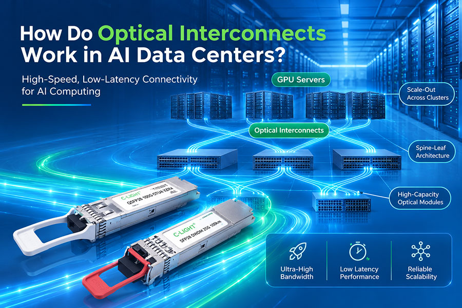
In AI data centers, these mechanisms are particularly important for Remote Direct Memory Access over Converged Ethernet version 2 (RoCEv2). Such networks may combine Priority Flow Control (PFC), ECN, and Data Center Quantized Congestion Notification (DCQCN) to reduce packet loss while controlling network congestion.
1. What Is Ethernet Flow Control?
Ethernet flow control regulates the rate at which one device transmits traffic toward a directly connected peer. When a receiving device needs temporary relief, it can send a control frame instructing the transmitting peer to pause traffic under the applicable flow-control mechanism.
The purpose is to prevent a receiver's buffers from overflowing when incoming traffic temporarily exceeds its ability to process or forward data. The pause mechanism does not increase the physical link's bandwidth or permanently remove congestion. It changes when the sender is allowed to transmit.
IEEE 802.3x PAUSE
Traditional Ethernet PAUSE flow control provides link-level control over a full-duplex Ethernet connection. A device experiencing congestion can transmit a PAUSE frame that instructs its directly connected peer to stop sending eligible traffic for a specified interval.
Because the mechanism applies to the link rather than an individual application flow, a PAUSE request can affect multiple traffic streams sharing that link. This can protect receive buffers, but it may also delay traffic that is not itself responsible for the congestion.
Priority Flow Control
Priority Flow Control, defined by IEEE 802.1Qbb, extends link-level pause behavior by allowing selected traffic priorities to be paused independently. Instead of stopping all eligible traffic on the link, PFC targets the configured priority classes.
This selective behavior is useful in data center networks that need to protect specific traffic, such as RoCEv2 RDMA, while allowing other traffic classes to continue whenever possible. The benefit depends on accurate traffic classification, consistent priority mapping, appropriate queue configuration, and compatible support at both ends of each link.
Key distinction: Ethernet PAUSE and PFC are link-level flow-control mechanisms. They can stop a directly connected sender temporarily, but they do not independently tell the original traffic source how congested the entire end-to-end path has become.
2. What Is Congestion Management?
Congestion management addresses situations in which network traffic demand exceeds the capacity or available buffering of one or more parts of the network. Unlike a pause command between adjacent devices, congestion-management mechanisms can use queue measurements, packet markings, feedback messages, and sender rate adjustments to control traffic across a path.
The goal is not simply to stop packets. It is to keep queues under control while maintaining useful throughput, acceptable latency, fair access to bandwidth, and reliable data delivery.
Queue Management
Switches buffer packets while waiting for an outgoing interface to become available. Queue-management policies determine how packets are admitted, marked, or dropped as queue occupancy changes.
Queue thresholds influence the response to congestion. If control action begins too late, buffers may overflow before senders react. If thresholds are too aggressive, traffic can be throttled unnecessarily and link utilization may suffer.
Explicit Congestion Notification
ECN enables a network device to indicate congestion by marking an eligible IP packet rather than immediately dropping it. In ECN-capable traffic, a switch can set the Congestion Experienced (CE) marking when configured queue or congestion conditions are met.
The receiving endpoint and transport protocol must support the appropriate feedback mechanism for that marking to influence the sender. For TCP, ECN signaling operates through TCP's congestion-control behavior. In RoCEv2 deployments using DCQCN, the destination NIC can generate a Congestion Notification Packet (CNP) to trigger the sender's rate-control response.
End-to-End Congestion Control
Congestion control adjusts the rate at which a source injects traffic into the network. It can use feedback indicating congestion along the path to reduce sending rates and allow queues to drain.
Unlike a link-level pause, an end-to-end control algorithm seeks to influence the source of the traffic rather than merely stopping an adjacent sender. Its effectiveness depends on feedback latency, algorithm design, traffic patterns, and appropriate configuration.
3. Flow Control vs. Congestion Management
| Characteristic | Ethernet Flow Control | Congestion Management |
|---|---|---|
| Primary objective | Protect buffers by regulating transmission from a directly connected peer. | Control traffic buildup and maintain performance across network paths. |
| Operating scope | Link-level, between adjacent Ethernet devices. | Can involve switch queues, network feedback, and end-to-end source behavior. |
| Typical mechanisms | IEEE 802.3x PAUSE and IEEE 802.1Qbb PFC. | Queue management, ECN, TCP congestion control, and algorithms such as DCQCN for supported RoCEv2 environments. |
| Reaction | Temporarily pauses all eligible traffic or selected priorities on a link. | May mark packets, change queue treatment, or adjust the sender's transmission rate. |
| Congestion feedback | Indicates that the adjacent receiver needs a pause, not necessarily the full path's congestion level. | Can provide information that influences traffic entering the wider network path. |
| Potential limitation | May propagate backpressure, delay unrelated traffic, or create prolonged pauses if poorly configured. | May respond too slowly or too aggressively if thresholds, feedback, or rate-control parameters are unsuitable. |
These mechanisms are complementary rather than interchangeable. Flow control can prevent a local buffer from overflowing, while congestion management can reduce the traffic pressure that caused the queue to grow in the first place.
4. How PAUSE, PFC, and ECN Interact
When a switch queue begins to build, several mechanisms may be involved depending on the network configuration. ECN can provide an early congestion signal, a congestion-control algorithm can reduce the source's sending rate, and PFC can act as a link-level protection mechanism if a protected queue continues approaching its buffer limit.
This sequence is a common design approach for RoCEv2 networks, not an automatic behavior of every Ethernet deployment. The actual response depends on whether ECN, congestion feedback, rate control, and PFC are supported and configured correctly across the path.
ECN and PFC thresholds must be coordinated. ECN marking is generally configured to begin before the queue reaches the PFC pause threshold, allowing end-to-end rate adjustment time to take effect. The required separation depends on traffic burstiness, link speed, feedback latency, buffer architecture, and switch implementation.
5. Why PFC Alone Is Not a Complete Congestion Solution
PFC can help create a lossless Ethernet behavior for selected priorities by preventing protected queues from overflowing. However, it is reactive and operates one link at a time. It does not inherently regulate the original traffic source based on congestion across the complete network path.
When a receiver pauses an upstream sender, the sender's own queues may start to fill. If the sender also experiences congestion, it may send a pause request to its upstream peer. This can propagate backpressure through multiple switches and affect traffic farther away from the original congested link.
Head-of-Line Blocking
When traffic is held up behind a paused queue or shares constrained resources with paused traffic, other packets may be delayed even if their own destination links are available. The extent of this effect depends on the queue architecture, traffic classification, and switch implementation.
Pause Propagation
Congestion on one link can cause upstream devices to stop sending traffic, moving the queue pressure elsewhere in the network. A large number of pause events can reduce throughput and introduce variable latency.
Long Pauses and Deadlock Risks
Incorrect configuration or persistent congestion can cause a priority to remain paused for excessive periods. In some network topologies and conditions, interacting pause dependencies can contribute to deadlock or widespread performance degradation.
Appropriate buffer thresholds, congestion control, watchdog mechanisms, monitoring, and topology-aware design help limit these risks. PFC should not be treated as a substitute for managing the source rate or understanding the network's traffic patterns.
6. Why ECN Is Important in AI and RoCEv2 Networks
AI training clusters generate bursty traffic as accelerators exchange gradients, synchronize computation, and move data between nodes. These workloads can create transient queue buildup, especially when many sources send traffic toward the same destination or switch output.
RoCEv2 carries RDMA traffic over an IP network and is commonly deployed with mechanisms intended to minimize packet loss. PFC can protect individual links, while ECN and algorithms such as DCQCN can regulate source transmission rates in response to congestion feedback.
In a typical DCQCN-based design, a switch marks eligible packets when congestion reaches the configured ECN threshold. The receiving NIC detects the congestion indication and may send a CNP to the original sender. The sender then adjusts its rate to reduce the load on the congested path.
This feedback approach aims to manage congestion before PFC needs to pause traffic. It does not mean PFC is unnecessary in every RoCEv2 deployment: the selected design may still use PFC to help prevent packet loss when congestion develops faster than the end-to-end control loop can react.
Design objective: Use congestion feedback to control the rate of traffic entering the network, while configuring link-level flow control and buffer protection to handle the conditions they are intended to address.
7. Configuration Factors That Affect Their Interaction
Flow control and congestion management depend on coordinated settings across NICs, switches, traffic classes, and the network topology. A configuration that works in a small test network may not behave the same way under large-scale AI traffic or microbursts.
Priority mapping: Ensure that application traffic is consistently classified into the intended traffic class across the hosts and switches.
PFC priorities: Enable PFC only for the intended priorities and confirm that adjacent devices use compatible priority mappings.
ECN thresholds: Configure marking thresholds appropriate to the queue capacity, traffic burst characteristics, and feedback delay.
PFC pause thresholds: Allow enough buffer headroom for traffic already in flight while a pause signal takes effect.
Congestion-control settings: Check the sender's rate-reduction behavior, recovery process, notification handling, and supported algorithm.
Buffer architecture: Consider shared and dedicated buffer limits, queue scheduling, and the effects of competing traffic classes.
Link capacity: Validate the combined impact of link speed, fan-in ratios, traffic distribution, and the capacity of the receiving interface.
Monitoring and protection: Track queue occupancy, ECN marks, PFC counters, pause duration, drops, and congestion-notification activity.
There is no universal threshold value suitable for every switch and AI fabric. The correct configuration depends on hardware buffer behavior, link speed, topology, endpoint implementation, and the application's traffic characteristics. Vendor guidance and measured performance should inform final settings.
8. Troubleshooting Common Flow-Control and Congestion Problems
| Observed Symptom | Possible Cause | Useful Checks |
|---|---|---|
| Frequent PFC pause events | Persistent queue buildup, incast traffic, insufficient egress capacity, or inappropriate pause thresholds. | Review queue occupancy, traffic fan-in, PFC counters, ECN marking activity, and buffer thresholds. |
| High latency despite few packet drops | Persistent queues, repeated pause propagation, or excessive buffering. | Check queue delay, pause duration, ECN feedback, traffic-class mapping, and end-to-end latency. |
| Low throughput with repeated pauses | Sources may remain paused too often, or congestion-control responses may not restore efficient utilization. | Correlate PFC events with sender rates, queue occupancy, ECN marks, and interface utilization. |
| ECN marking without effective rate reduction | Endpoint feedback, traffic classification, or congestion-control configuration may be incorrect or unsupported. | Verify ECN-capable traffic, CE marks, feedback packets, NIC counters, and sender algorithm configuration. |
| Packet drops in a supposedly protected priority | Buffer exhaustion may occur before the pause takes effect, or priority mappings and flow-control settings may be inconsistent. | Check queue thresholds, in-flight data, PFC configuration, drop counters, and link-level compatibility. |
| Performance degradation across multiple links | Pause propagation, shared-buffer pressure, uneven load distribution, or a broader congestion problem. | Compare switch-by-switch queue data, pause counters, ECN activity, traffic paths, and load distribution. |
Counter names and available telemetry vary by vendor and platform. Troubleshooting should correlate measurements from both sides of the link and across the network path rather than treating one counter as definitive proof of the root cause.
9. How Physical Links Support Congestion Management
Flow control and congestion management operate primarily in the MAC, switch-queue, network, and endpoint protocol layers. Optical transceivers and cables provide the physical connectivity over which these mechanisms operate, but they do not independently implement the network's congestion-control policy.
High-speed optical links must still meet their intended data rate, signal-integrity, and error-performance requirements. Physical-layer faults or excessive errors can complicate congestion diagnosis, but increasing optical bandwidth alone does not prevent queue buildup when the network's traffic demand exceeds the capacity of an output link.
In AI data centers, reliable congestion management therefore requires both a sound physical network and a carefully configured traffic-control design. Engineers should evaluate interface capacity, link health, queue behavior, PFC, ECN, and endpoint congestion feedback as parts of one system.
10. Conclusion
Ethernet flow control and congestion management solve related but different problems. Ethernet PAUSE and PFC provide link-level protection by temporarily stopping transmission when a receiver needs buffer relief. Congestion management mechanisms such as ECN and end-to-end rate control work to reduce traffic pressure and stabilize network performance.
In RoCEv2 AI networks, combining ECN-based feedback with appropriately configured PFC can help balance high throughput, low latency, and loss avoidance. ECN can signal growing queues early, while congestion-control algorithms reduce source rates. PFC can provide additional link-level protection when congestion persists or develops faster than the feedback loop can react.
The result depends on accurate traffic classification, coordinated thresholds, appropriate buffer design, compatible endpoints, and continuous monitoring. Neither flow control nor congestion management should be configured in isolation; both need to reflect the actual network topology and workload behavior.
11. Frequently Asked Questions
What is the difference between Ethernet PAUSE and PFC?
Traditional Ethernet PAUSE can stop all eligible traffic on a link, while PFC allows selected priority classes to be paused independently. Both operate at link level between directly connected devices.
Does Ethernet flow control prevent all congestion?
No. It can temporarily protect a receiver's buffers, but it does not increase link capacity or independently manage congestion throughout the entire network. Congestion may persist or propagate upstream.
How does ECN interact with PFC?
ECN marks eligible packets to signal congestion before buffers overflow. PFC pauses a specific priority on a link when a configured threshold is reached. In appropriately designed networks, ECN-based rate control acts early and PFC provides additional buffer protection if queue pressure continues to rise.
What is DCQCN?
Data Center Quantized Congestion Notification is an end-to-end congestion-control algorithm used in some RoCEv2 deployments. It uses congestion feedback, commonly involving ECN marking and congestion notification packets, to adjust the sending rate.
Why can excessive PFC reduce network performance?
Repeated pauses can delay traffic, propagate backpressure upstream, and contribute to head-of-line blocking. Poorly coordinated configurations can also cause prolonged pauses and other network-wide performance problems.
Should ECN thresholds always be lower than PFC thresholds?
A common design approach is to trigger ECN before PFC so that end-to-end rate control has time to react. The precise relationship must be engineered for the hardware buffer architecture, traffic pattern, link speed, and feedback delay.
Does a higher-speed Ethernet link eliminate congestion?
No. Higher bandwidth can reduce congestion when the link was the limiting resource, but traffic can still exceed the capacity of an output port or shared network path. Queue management, traffic distribution, flow control, and congestion control remain important.
Designing high-speed Ethernet or AI cluster networks?
Evaluate link capacity, traffic priorities, queue thresholds, and congestion feedback together to improve network stability and performance.
Contact C-LIGHT >

 >
 >
 >
 >
 >
 >
 >