TEL:+86 132 6656 7067




Data center fiber cabling provides the physical optical infrastructure for connecting servers, switches, storage systems, AI clusters, and data center interconnects. Proper fiber selection, connector design, polarity, cable management, loss control, and testing are essential for reliable 100G, 400G, 800G, and emerging 1.6T networks.
1. What Is Data Center Fiber Cabling?
Data center fiber cabling is the structured optical cabling infrastructure used to transport high-speed data between network devices. It includes fiber cables, patch cords, trunks, connectors, adapters, cassettes, patch panels, and related cable-management components.
Unlike point-to-point fiber installations, structured cabling is designed to provide an organized and scalable physical layer for future network changes.
2. Why Fiber Cabling Is Important in Data Centers
Modern data centers require large numbers of high-speed connections. As network speeds increase from 100G to 400G, 800G, and 1.6T, the physical fiber infrastructure must support higher bandwidth while maintaining low insertion loss, correct polarity, and efficient cable management.
3. Data Center Fiber Cabling Architecture
A structured fiber system can include equipment-side patching, fiber trunks, cross-connects, patch panels, and horizontal or backbone cabling.
The exact architecture depends on whether the installation is designed for a single rack, a data hall, a campus environment, or an inter-data-center connection.
4. Main Components of Fiber Cabling
Fiber cable: Provides the optical transmission path.
Patch cord: Connects equipment or patching points.
Trunk cable: Provides multiple pre-terminated fiber connections in one assembly.
Patch panel: Organizes fiber connections and simplifies cross-connects.
Adapter: Provides mechanical alignment between connectors.
Cassette: Converts and organizes multi-fiber trunk connections into equipment interfaces.
5. Multimode vs Single-Mode Fiber
| Feature | Multimode Fiber | Single-Mode Fiber |
|---|---|---|
| Typical application | Short data center links | Longer data center and DCI links |
| Common wavelength | 850nm-class | 1310nm or 1550nm-class |
| Typical optical source | VCSEL | DFB, EML, silicon photonics, or other sources |
| Reach potential | Shorter | Longer |
6. OM3 Fiber
OM3 is a laser-optimized multimode fiber commonly used for short-reach data center applications. It supports high-speed 850nm optical transmission and is often associated with VCSEL-based transceivers.
7. OM4 Fiber
OM4 provides improved modal bandwidth compared with OM3 and is widely used for higher-speed short-reach data center links.
It can provide additional reach for many 850nm-based applications while maintaining multimode fiber compatibility.
8. OM5 Fiber
OM5 is a wideband multimode fiber designed to support short-wavelength wavelength-division multiplexing applications. It can provide greater flexibility for selected multi-wavelength multimode architectures.
9. OS2 Single-Mode Fiber
OS2 is widely used for single-mode data center and telecommunications cabling. It is suitable for longer optical links and is commonly used with 1310nm and 1550nm-class transceivers.
10. Fiber Type Selection
Fiber should be selected according to the transceiver, wavelength, transmission distance, network generation, and expected upgrade path.
Using a fiber that exceeds the immediate requirement can sometimes simplify future upgrades, but the overall cost and infrastructure design should also be considered.
11. Fiber Cabling for 10G
10G data center networks commonly use multimode SR optics for short links and single-mode LR or other optical solutions for longer paths.
12. Fiber Cabling for 25G
25G server and switch networks can use multimode or single-mode optical connections depending on the transceiver and required reach.
13. Fiber Cabling for 100G
100G networks can use several optical architectures. SR4 is commonly associated with multimode fiber, while DR, LR4, ER4, and related solutions use single-mode fiber for longer distances.
14. Fiber Cabling for 400G
400G networks can use parallel multimode optics, parallel single-mode optics, or wavelength-multiplexed architectures depending on the transceiver.
Examples include SR8, DR4, FR4, and other 400G optical designs.
15. Fiber Cabling for 800G
800G introduces significantly higher lane rates and increasingly diverse optical architectures. SR8, DR8, 2FR4, 2DR4, and other designs can require different fiber and connector configurations.
16. Fiber Cabling for 1.6T
1.6T networks place even greater demands on fiber count, connector density, optical loss, polarity management, and cable routing.
Depending on the optical architecture, 1.6T may use multiple fibers, multiple wavelengths, or combinations of parallel and wavelength-multiplexed transmission.
17. Duplex Fiber Cabling
Duplex fiber uses two fibers, typically one for transmission and one for reception. This remains a common architecture for many optical transceivers with separate Tx and Rx paths.
18. Parallel Fiber Cabling
Parallel optics use multiple fibers to carry different optical lanes. MPO-based systems are commonly used to simplify the physical management of these multi-fiber connections.
19. MPO Fiber Cabling
MPO connectors are designed to terminate multiple optical fibers in a single connector. They are widely used for high-density 40G, 100G, 200G, 400G, and 800G applications.
20. MPO-12
MPO-12 contains 12 fiber positions and is widely used in high-density optical connectivity. Depending on the transceiver architecture, some fibers can remain unused while others carry active optical lanes.
21. MPO-16
MPO-16 provides 16 fiber positions and can support higher-density parallel optical architectures. Some 800G applications use MPO-16-based interfaces.
22. MPO vs LC
| Feature | MPO | LC |
|---|---|---|
| Fiber count | Multi-fiber | Typically one fiber per connector position |
| Density | High | Lower |
| Typical use | Parallel optics and trunks | Duplex and WDM optics |
| Handling | Polarity-sensitive | Simpler point-to-point handling |
23. LC Fiber Cabling
LC connectors are widely used for duplex and wavelength-multiplexed optical transceivers. Their compact size makes them suitable for high-density equipment panels.
24. SC Fiber Cabling
SC connectors are larger than LC connectors and remain common in access and PON networks. They are less common than LC and MPO for modern high-density data center switching.
25. Fiber Polarity
Fiber polarity ensures that the transmitter at one end connects to the receiver at the other end. Incorrect polarity can prevent an optical link from establishing even when all connectors are physically compatible.
26. MPO Polarity
MPO systems require particularly careful polarity planning because multiple fibers are carried through one connector. Type A, Type B, Type C, and associated trunk configurations must be matched correctly to the transceiver and network architecture.
27. MPO Key Orientation
The key orientation of an MPO connector determines how the fiber positions align between the two ends. Incorrect key orientation can reverse the expected fiber mapping.
28. Fiber Polarity Testing
Polarity should be verified before connecting high-speed transceivers. Visual identifiers, polarity testers, and documented fiber maps can help prevent installation errors.
29. Fiber Insertion Loss
Insertion loss is the reduction in optical power caused by the fiber connection and associated components.
Total insertion loss can include connector loss, splice loss, adapter loss, patch panel loss, cassette loss, and other passive components in the optical path.
30. Fiber Link Budget
An optical link budget compares the transmitter's available optical power with the receiver's required input after all channel losses and penalties are considered.
The cabling system must keep total loss within the margin supported by the transceiver.
31. Connector Loss
Each connector introduces some optical loss. A system with a large number of patch points can therefore consume significantly more optical budget than a direct connection.
32. Splice Loss
Fusion and mechanical splices can introduce additional loss. The number and quality of splices should be documented as part of the complete fiber path.
33. Bend Loss
Excessive fiber bending can increase optical attenuation and may permanently affect cable performance if the bend exceeds the specified limits.
Respecting the cable's minimum bend radius is essential during installation and maintenance.
34. Fiber Bend Radius
The minimum bend radius depends on the cable construction and whether the cable is under tension. Manufacturers typically specify installation and operating bend-radius limits.
35. Fiber Cable Management
Good cable management should maintain bend-radius requirements, avoid excessive tension, separate pathways where necessary, and provide sufficient slack for equipment movement.
36. Fiber Trunk Cables
Pre-terminated trunk cables combine multiple optical fibers into a single high-density assembly. They can significantly reduce installation time compared with terminating every fiber individually in the field.
37. MTP/MPO Trunk Cabling
MTP is a performance-enhanced implementation of the MPO connector family. MTP/MPO trunk systems are widely used for high-density parallel optical connections and structured cabling.
38. Fiber Cassettes
Fiber cassettes organize multi-fiber trunks and convert them into equipment-side connectors such as LC. This can simplify patching and provide a more structured connection point.
39. Fiber Patch Panels
Patch panels provide centralized locations for fiber cross-connects. They make moves, adds, and changes easier and help protect equipment ports from repeated cable handling.
40. Structured Fiber Cabling
Structured fiber cabling separates the permanent cabling infrastructure from replaceable equipment patching. This approach improves organization, serviceability, and future upgrade flexibility.
41. Main Distribution Area
The Main Distribution Area, or MDA, can serve as a central point for aggregation and cross-connect functions. High-density fiber patching is often concentrated in this area.
42. Horizontal Distribution Area
Horizontal distribution connects equipment areas or racks to distribution points. Fiber trunks can simplify large-scale deployment across a data hall.
43. Equipment Distribution Area
The Equipment Distribution Area is where network and computing equipment is physically installed. Short patch cords and high-density optical connections are often concentrated here.
44. Data Center Fiber Cabling Topology
A structured topology can be designed around equipment zones, distribution zones, and backbone fiber paths. The objective is to minimize unnecessary cable complexity while allowing future changes.
45. Fiber Cabling for Leaf-Spine Networks
Leaf-spine architectures require large numbers of high-speed connections between switches. MPO trunks can simplify large groups of parallel optical connections, while duplex LC cabling remains useful for WDM-based modules.
46. Fiber Cabling for AI Data Centers
AI data centers can have extremely high optical port density. 400G, 800G, and 1.6T connections create strong requirements for fiber density, connector organization, polarity control, and optical loss management.
47. Fiber Cabling for GPU Clusters
GPU clusters use optical connectivity primarily across racks and switching layers. The fiber infrastructure must support the network's traffic capacity while remaining manageable at high port counts.
48. Fiber Cabling for HPC
HPC environments similarly require high-throughput, low-latency optical connectivity. Fiber cabling can support both Ethernet and InfiniBand architectures depending on the network design.
49. Fiber Cabling for InfiniBand
InfiniBand networks can use high-density optical transceivers and active optical cables. The physical fiber architecture must match the connector, lane mapping, polarity, and supported reach of the specific system.
50. Fiber Cabling for Ethernet
Ethernet data center networks use a wide range of fiber configurations depending on port speed and optical architecture.
As Ethernet speeds increase, multi-fiber connectors and higher-density structured cabling become increasingly important.
51. Fiber Cabling for DCI
Data Center Interconnect can require substantially longer optical paths than intra-data-center networking. Single-mode fiber is generally preferred for DCI because it supports longer transmission distances.
52. Coherent Optics and DCI Cabling
Coherent pluggables used for DCI typically operate over single-mode fiber and may connect to DWDM, ROADM, and optical amplification systems.
53. DWDM Fiber Cabling
DWDM networks use multiple optical wavelengths over the same fiber pair. Fiber cabling must therefore maintain low loss and suitable connector performance across the wavelengths used by the system.
54. Fiber Cabling for 400G FR4
400G FR4 typically uses single-mode fiber and duplex LC connectivity because multiple LAN-WDM wavelengths are multiplexed into the optical path.
55. Fiber Cabling for 400G DR4
400G DR4 commonly uses multiple single-mode fiber lanes and a multi-fiber connector such as MPO. The connector and polarity configuration must match the specific transceiver.
56. Fiber Cabling for 800G SR8
800G SR8 uses parallel multimode optical lanes and therefore requires an appropriate multi-fiber cabling architecture. The exact connector depends on the transceiver implementation.
57. Fiber Cabling for 800G DR8
800G DR8 uses parallel single-mode optical lanes. High-density MPO-based cabling can simplify the physical connection between the transceiver and structured fiber infrastructure.
58. Fiber Cabling for 800G 2xFR4
800G 2xFR4 uses wavelength-multiplexed optical channels and can use dual LC optical interfaces depending on the transceiver design. The cabling therefore differs from parallel MPO-based architectures.
59. Fiber Cabling for 800G 2xDR4
800G 2xDR4 uses two 400G-class optical groups and requires a connector architecture appropriate for the specific module. Some implementations use dual MPO-12 interfaces.
60. Fiber Cabling and 1.6T Architectures
1.6T optical architectures can use a mixture of parallel optics and wavelength multiplexing. The cabling design must therefore begin with the exact transceiver interface rather than assuming a single standard fiber configuration.
61. Fiber Connector Density
Higher-speed networks require more lanes and more connections. MPO and related multi-fiber connectors help reduce the number of individual connector positions required on equipment and patch panels.
62. High-Density Fiber Panels
High-density panels can organize large numbers of optical connections in limited rack space. Proper labeling and access clearance are important because dense fiber systems can become difficult to troubleshoot.
63. Fiber Labeling
Every trunk, patch cord, panel position, cassette, and cross-connect should be clearly labeled. Consistent labeling reduces installation errors and makes troubleshooting much faster.
64. Fiber Route Identification
For large data centers, documentation should identify both endpoints of each permanent fiber path. This is particularly important when dozens or hundreds of parallel fibers are installed between switching areas.
65. Fiber Polarity Documentation
Polarity documentation should include connector type, key orientation, fiber numbering, Tx/Rx mapping, and the associated equipment ports.
66. Cleaning Fiber Connectors
Contamination is one of the most common physical-layer problems in fiber networks. Dust or residue on a connector end face can increase insertion loss, reflection, or even interrupt the optical connection.
67. Fiber Inspection
Connector end faces should be inspected with appropriate fiber inspection equipment when installing or troubleshooting high-speed optical links.
68. Cleaning Before Connection
Cleaning should be performed before connection rather than assuming factory-clean connectors remain clean after handling.
69. Fiber Testing
Fiber cabling should be tested after installation and whenever a major change is made. Typical measurements include insertion loss and polarity, while more advanced validation can include return loss, OTDR analysis, and end-to-end optical testing.
70. Optical Loss Testing
An optical loss test set can measure the total insertion loss of a fiber channel. The measured value should be compared with the allowable loss budget for the intended transceiver.
71. OTDR Testing
Optical Time-Domain Reflectometry can help locate splices, high-loss events, connectors, and other discontinuities along a fiber path.
OTDR is particularly useful when troubleshooting long fiber routes or identifying the location of unexpected loss.
72. End-to-End Fiber Testing
End-to-end testing verifies the complete installed channel, including connectors, patch panels, cassettes, trunks, and patch cords.
73. Fiber Cabling vs Active Optical Cables
Structured fiber cabling uses separate passive fiber infrastructure and optical transceivers at the endpoints. AOC integrates the optical engines and fiber into one cable assembly.
Structured cabling provides greater patching flexibility, while AOC can simplify short fixed connections.
74. Fiber Cabling vs DAC
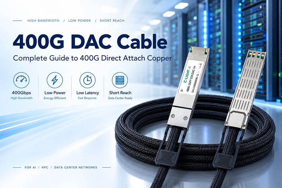
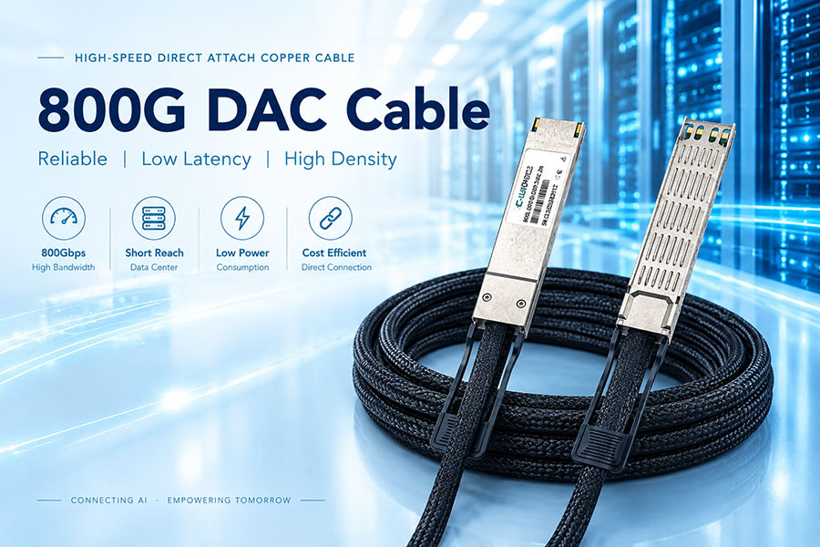
DAC provides direct copper connectivity and is generally used for very short links. Fiber cabling is preferred when optical reach, electromagnetic isolation, cable density, or network architecture requires optical transmission.
75. Fiber Cabling vs AEC
AEC extends electrical copper connectivity through active signal conditioning. It can be useful between the very short range of passive DAC and the optical range of fiber-based solutions.
76. Cable Density and Airflow
Fiber cables are generally smaller and lighter than equivalent large copper bundles. This can simplify cable management and airflow in high-density data center environments.
77. Fiber Cabling and Cooling
Passive fiber itself generates no electrical heat. However, the connected optical transceivers and active equipment generate power and therefore contribute to overall thermal load.
78. Fiber Cabling and Network Scalability
Structured fiber systems should be designed with future network growth in mind. Spare fibers, modular panels, sufficient rack space, and standardized connectors can make future upgrades easier.
79. Spare Fiber Capacity
Installing spare fibers can avoid expensive recabling when network capacity expands. The appropriate reserve depends on the expected growth rate and importance of the route.
80. Migration from 100G to 400G
A migration from 100G to 400G may change the required connector architecture, fiber count, polarity, and optical loss budget.
Existing fiber infrastructure should therefore be audited before assuming that every 100G path can directly support a 400G upgrade.
81. Migration from 400G to 800G
800G can require different transceiver connectors, lane counts, or wavelength architectures. The fiber plant must be evaluated for insertion loss, connector compatibility, polarity, and physical density.
82. Migration from 800G to 1.6T
1.6T deployment can increase connector density and impose tighter optical performance requirements. Structured cabling should be planned with future higher-speed architectures in mind.
83. Fiber Cabling for AI Network Expansion
AI clusters can expand rapidly. Modular trunks, high-density patch panels, documented polarity, and spare fiber capacity can reduce the complexity of future GPU and switch deployments.
84. Fiber Cabling and Port Breakout
Breakout configurations can divide one high-speed port into several lower-speed connections. The associated fiber architecture must match the optical lane mapping and connector configuration.
85. MPO Breakout Cabling
MPO-to-LC breakout assemblies can convert a multi-fiber trunk into individual duplex LC interfaces where required. This is useful for connecting multi-fiber switching ports to multiple lower-speed optical interfaces.
86. Fiber Polarity in Breakout Systems
Breakout systems require particularly careful polarity planning because one multi-fiber connector is mapped to several individual optical channels. Documentation should clearly define the mapping before installation.
87. Fiber Cable Bend and Routing
Routing should avoid sharp bends, excessive pulling force, and pressure from cable-management hardware. High-density optical installations require sufficient space for cable movement and maintenance.
88. Fiber Cable Weight
Large fiber trunks can still create mechanical loads in high-density installations. Cable supports should be selected according to the installed cable quantity and building or rack design.
89. Fiber Cabling in High-Density AI Racks
AI racks can contain large numbers of 400G and 800G optical connections. Fiber routing must maintain airflow, service access, bend-radius requirements, and clear identification of individual connections.
90. Data Center Fiber Cabling Best Practices
Use a structured design, match fiber type to the transceiver, minimize unnecessary connection points, maintain correct polarity, clean and inspect connectors, document every route, test installed channels, and reserve capacity for future upgrades.
91. Data Center Fiber Cabling Selection Checklist
| Parameter | What to Verify |
|---|---|
| Fiber type | OM3, OM4, OM5, OS2, or required fiber |
| Connector | LC, MPO-12, MPO-16, or required interface |
| Polarity | Correct Tx/Rx mapping and connector orientation |
| Distance | Actual installed channel length |
| Loss | Total insertion loss within link budget |
| Bend radius | Installation and operating limits |
| Density | Panel and rack capacity |
| Testing | Insertion loss, polarity, and required certification tests |
92. Future Data Center Fiber Cabling
Future AI data centers will require increasingly dense optical infrastructure as 800G, 1.6T, and higher-speed connectivity become more common.
Higher-density MPO systems, improved fiber management, lower-loss components, structured trunks, and better testing practices will become increasingly important.
93. Conclusion
Data center fiber cabling is the physical foundation of modern high-speed optical networking. The cabling system must be designed around the requirements of the optical transceiver, including fiber type, connector, lane architecture, polarity, distance, and optical loss.
For 100G, 400G, 800G, and 1.6T networks, proper structured cabling can improve scalability, reliability, serviceability, and migration flexibility. OM3, OM4, OM5, and OS2 address different application requirements, while LC, MPO-12, and MPO-16 provide different connector densities and optical architectures.
The most reliable data center fiber installation is one that considers the complete optical channel rather than the cable alone. Connector cleanliness, polarity, insertion loss, bend radius, cable routing, testing, documentation, and future capacity should all be included in the design.
 >
>

 >
>
 >
>
 >
>
 >
>
 >
>
 >
>
 >
>