TEL:+86 132 6656 7067




400G optical transceivers are increasingly used in modern data centers, cloud networks, high-performance computing, and AI infrastructure. Among the commonly deployed 400G optical solutions, SR8, FR4, and LR4 address different transmission distances and fiber architectures.
400G SR8 is designed for short-reach multimode fiber connections, while 400G FR4 and LR4 use single-mode fiber and wavelength-division multiplexing for longer transmission distances. Although all three provide 400G connectivity, their optical architecture, wavelength configuration, connector type, fiber requirements, and deployment scenarios are different.
Understanding these differences is important when selecting a 400G optical module for switch-to-switch links, leaf-spine networks, server connectivity, AI data centers, and other high-speed network applications.
1. What Are 400G SR8, FR4, and LR4?
400G SR8, 400G FR4, and 400G LR4 are different 400G optical transmission solutions. The suffixes describe the optical architecture and intended reach rather than the pluggable form factor itself.
SR8 is a short-reach, eight-lane multimode optical architecture. FR4 uses four wavelength channels over single-mode fiber for links around 2 km. LR4 also uses four wavelength channels over single-mode fiber, with the standardized 400GBASE-LR4-6 interface covering at least 6 km, while some commercial modules extend the reach to 10 km.
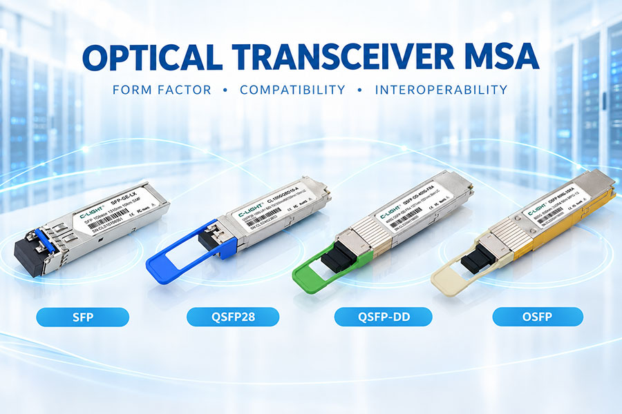
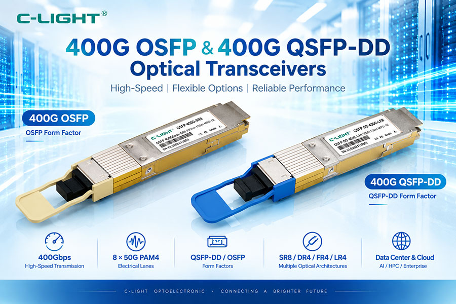
These optical interfaces can be implemented in different pluggable form factors such as QSFP-DD and OSFP.
2. 400G SR8 vs FR4 vs LR4: Basic Comparison
| Feature | 400G SR8 | 400G FR4 | 400G LR4 |
|---|---|---|---|
| Typical Reach | Up to 100m | Up to 2km | At least 6km for 400GBASE-LR4-6; some modules support 10km |
| Fiber Type | Multimode Fiber (MMF) | Single Mode Fiber (SMF) | Single Mode Fiber (SMF) |
| Typical Fiber | OM4 / OM5 | OS2 / SMF | OS2 / SMF |
| Optical Lanes | 8 | 4 | 4 |
| Optical Wavelength | 850nm class | Four CWDM wavelengths | Four CWDM wavelengths |
| Signaling | PAM4 | PAM4 | PAM4 |
| Common Connector | MPO-16 | Duplex LC | Duplex LC |
| Typical Application | Short data center links | Inter-rack and data center links | Longer data center and campus links |
3. 400G SR8 Architecture
400G SR8 uses eight parallel optical lanes to provide an aggregate 400G connection. Each optical lane operates at approximately 50G-class PAM4, with an optical signaling rate of approximately 53.125 GBd.
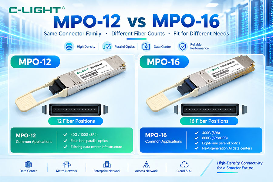
The eight optical channels require eight transmit paths and eight receive paths. As a result, the optical interface typically uses a 16-fiber connection, commonly implemented with an MPO-16 connector.
SR8 is designed for multimode fiber and short-reach applications. Its simple parallel optical architecture makes it suitable for high-density connections where the link distance is relatively short.
4. 400G FR4 Architecture
400G FR4 uses four optical wavelengths over single-mode fiber. Each wavelength carries approximately 100G-class PAM4 signaling, with the four wavelengths combined to provide a total 400G link.
The four optical channels are multiplexed inside the module before transmission and separated by a demultiplexer at the receiver.
Because four wavelengths share a duplex fiber pair, FR4 can provide 400G connectivity through a standard LC duplex interface while significantly reducing the number of fibers compared with parallel SR8 solutions.
5. 400G LR4 Architecture
400G LR4 uses a similar four-wavelength architecture to FR4 but is designed for longer transmission distances.
The standardized IEEE interface is commonly referred to as 400GBASE-LR4-6 and specifies a reach of at least 6 km over single-mode fiber. Commercial products based on the broader 400G LR4 ecosystem can extend this reach to 10 km, so the actual distance should always be checked against the individual module datasheet.
Like FR4, LR4 uses four wavelength channels combined onto a duplex single-mode fiber interface.
6. Why Does SR8 Use Eight Optical Lanes?
SR8 uses parallel optics because short-reach multimode links can provide high bandwidth without requiring wavelength multiplexing.
Each optical lane carries part of the 400G traffic. Eight optical lanes therefore allow the module to maintain the required aggregate bandwidth while using 850nm-class VCSEL technology and multimode fiber.
The trade-off is the larger number of optical fibers and a higher-density optical connector.
7. Why Do FR4 and LR4 Use Four Wavelengths?
FR4 and LR4 use wavelength-division multiplexing to combine four optical channels onto a duplex single-mode fiber pair.
Each wavelength carries approximately 100G-class PAM4 traffic. The four channels are then multiplexed into a single optical path.
This architecture reduces the number of fibers needed for 400G transmission and allows the modules to use duplex LC connectors, which can simplify cabling in networks where single-mode fiber infrastructure is already installed.
8. SR8 vs FR4 vs LR4 Fiber Type
The most fundamental cabling difference is the fiber type.
400G SR8 is designed for multimode fiber, commonly OM4 or OM5. FR4 and LR4 are designed for single-mode fiber.
| Module | Fiber | Typical Fiber Infrastructure |
|---|---|---|
| 400G SR8 | MMF | OM4 / OM5 |
| 400G FR4 | SMF | OS2 / single-mode fiber |
| 400G LR4 | SMF | OS2 / single-mode fiber |
This means that SR8 is normally selected for existing multimode data center cabling, while FR4 and LR4 are used when single-mode fiber is required for longer reach.
9. 400G SR8 Wavelength and VCSEL
400G SR8 modules commonly use 850nm-class VCSEL transmitters for multimode fiber.
VCSEL technology is well suited to short-reach data center applications because it can provide high-speed modulation with efficient coupling into multimode fiber.
Because SR8 uses parallel optical lanes rather than multiple wavelengths on the same fiber, the optical architecture does not require the wavelength multiplexing and demultiplexing components used in FR4 and LR4.
10. 400G FR4 and LR4 Wavelength Architecture
FR4 and LR4 use four optical wavelengths in the 1310nm region and combine them using wavelength-division multiplexing.
The four wavelength channels are separated at the receiver by an optical demultiplexer. This architecture allows four independent optical channels to share a duplex single-mode fiber connection.
The use of wavelength multiplexing increases the optical complexity of the module but substantially reduces fiber count compared with an eight-lane parallel optical implementation.
11. PAM4 Signaling in 400G Modules
All three architectures use PAM4-based high-speed optical signaling in modern 400G implementations.
PAM4 uses four signal levels and carries two bits per symbol. This allows approximately twice the bit density per symbol compared with NRZ.
For 400G modules, PAM4 enables each electrical and optical lane to carry approximately 50G-class payload traffic. This makes eight-lane SR8 and four-lane 100G-class-per-wavelength FR4/LR4 architectures practical within the 400G generation.
12. Electrical Interface and Optical Interface
A 400G optical module has two separate sides: the electrical host interface and the optical line interface.
The host side commonly uses an eight-lane 400GAUI-8 electrical interface. The optical side can then use eight parallel lanes, as in SR8, or four wavelength channels, as in FR4 and LR4.
This distinction explains why different optical architectures can provide the same 400G aggregate bandwidth while having different optical connector and fiber configurations.
13. 400G SR8 Connector
Because SR8 uses eight transmit and eight receive optical lanes, a high-density multi-fiber connector is required.
MPO-16 is commonly used for 400G SR8 because it provides the required fiber count in a compact connector.
Polarity, key orientation, fiber mapping, and connector quality are important in SR8 systems because every optical lane must connect to the correct transmitter or receiver channel.
14. 400G FR4 Connector
FR4 uses four wavelength channels that are multiplexed onto two single-mode fibers. Therefore, the standard optical interface can use a duplex LC connector.
This can simplify cabling compared with a multi-fiber SR8 interface, especially when the data center already uses duplex LC single-mode patching.
The optical transmission still contains four independent channels, but they are combined internally before reaching the connector.
15. 400G LR4 Connector
LR4 uses the same basic duplex single-mode fiber interface as FR4.
The difference is primarily the optical reach and the associated link budget and transmitter/receiver performance requirements.
A duplex LC connector therefore allows LR4 modules to connect to standard single-mode fiber infrastructure while supporting longer 400G links than short-reach parallel multimode solutions.
16. Transmission Distance
Transmission distance is one of the easiest ways to distinguish the three architectures.
| Solution | Typical Reach | Recommended Use |
|---|---|---|
| 400G SR8 | Up to 100m | Short data center links |
| 400G FR4 | Up to 2km | Inter-rack and data center interconnects |
| 400G LR4 | At least 6km; some modules support 10km | Longer data center and campus links |
Actual reach depends on the module specification, optical budget, fiber quality, connector loss, and installation conditions.
17. Optical Power Budget
Optical power budget is especially important for FR4 and LR4 because the transmission distance is longer and the link uses single-mode fiber.
The available optical budget is determined by the difference between transmitter output power and receiver sensitivity. The total link loss includes fiber attenuation, connector loss, splice loss, and any other passive optical components.
For a longer link, the available optical margin must be sufficient to cover all losses while maintaining acceptable receiver performance.
18. Fiber Attenuation
Fiber attenuation contributes directly to the total optical loss of a link.
Multimode and single-mode fibers have different transmission characteristics. SR8 operates over multimode fiber at approximately 850nm, while FR4 and LR4 use single-mode fiber in the 1310nm region.
When calculating a link budget, the attenuation value should be taken from the actual fiber specification and applied to the wavelength being used.
19. SR8 vs FR4 vs LR4 Power and Complexity
SR8 has a relatively straightforward parallel optical architecture but requires more optical fibers and a high-density connector.
FR4 and LR4 require wavelength multiplexing and demultiplexing components, increasing optical complexity. However, the duplex LC interface significantly reduces the fiber count at the network level.
As a result, the choice involves a trade-off between optical architecture, cabling density, transmission distance, and system complexity.
20. 400G SR8 Applications
400G SR8 is primarily suited to short-reach high-bandwidth links inside data centers.
Typical applications include switch-to-switch connections within a rack or between adjacent racks, high-density spine-leaf connections, and short-distance AI or HPC network links.
SR8 is particularly useful when OM4 or OM5 multimode fiber infrastructure is already available and the required link distance is within the SR8 specification.
21. 400G FR4 Applications
400G FR4 is designed for single-mode links up to approximately 2km and is commonly used when a data center requires more reach than multimode SR8 can provide.
The duplex LC interface makes FR4 suitable for environments using single-mode duplex cabling.
FR4 can also provide a practical connection between different areas of a data center where the distance exceeds the reach of conventional multimode solutions.
22. 400G LR4 Applications
400G LR4 is intended for longer single-mode fiber links. The standardized 400GBASE-LR4-6 specification supports at least 6km, while some commercial 400G LR4 modules extend to 10km.
This makes LR4 suitable for longer data center interconnects, campus-style connections, and other environments where a 400G link must span a greater distance.
The longer reach requires a higher-performance optical design and a link budget appropriate for the target distance.
23. 400G SR8 for AI Data Centers
AI clusters require large numbers of high-bandwidth connections between GPUs, switches, servers, and storage systems.
For short connections within a data center, 400G SR8 can provide high bandwidth through parallel multimode optics while maintaining a compact pluggable form factor.
The eight-lane optical architecture also aligns naturally with high-density 400G switch ports and can support certain breakout configurations where the host platform allows them.
24. 400G FR4 and LR4 for Data Center Interconnect
Single-mode solutions become more useful when links extend beyond the practical reach of multimode fiber.
FR4 can provide up to 2km connectivity using four wavelength channels, while LR4 extends the reach further. The duplex LC architecture also allows the modules to use standard single-mode patching with a relatively low fiber count.
These characteristics make FR4 and LR4 suitable for longer connections between data center network areas and other single-mode fiber environments.
25. Breakout Applications
400G modules can support different breakout architectures depending on the module and host platform.
SR8 can be used in certain 400G-to-200G or 400G-to-50G breakout configurations because its eight optical lanes can be mapped into multiple lower-speed channels.
FR4 and LR4 can also support breakout-related applications where the host electrical and optical mapping is designed for such operation, but the exact configuration must be verified from the module datasheet.
26. SR8 vs FR4 vs LR4 Cabling
| Item | 400G SR8 | 400G FR4 | 400G LR4 |
|---|---|---|---|
| Fiber Type | MMF | SMF | SMF |
| Typical Fiber | OM4 / OM5 | OS2 | OS2 |
| Fiber Count at Optical Interface | 16-fiber interface | 2 fibers | 2 fibers |
| Connector | MPO-16 | Duplex LC | Duplex LC |
| Wavelength Architecture | 850nm-class parallel optics | 4-WDM | 4-WDM |
27. Module Form Factors
The optical interface specification does not necessarily determine the mechanical form factor of the module.
400G SR8, FR4, and LR4 optical solutions can be implemented in form factors such as QSFP-DD and OSFP, depending on the networking platform.
Therefore, when selecting a 400G module, both the optical standard and the host form factor must be checked.
28. Compatibility Considerations
Compatibility should be evaluated at several levels.
The host switch must support the required module form factor and electrical interface. The optical side must match the fiber type, wavelength architecture, connector, and transmission distance. Module coding and firmware support may also affect interoperability.
For SR8, the MPO-16 connector and fiber polarity must be matched correctly. For FR4 and LR4, the duplex LC single-mode optical path must meet the appropriate link budget.
29. SR8 vs FR4 vs LR4: How to Choose
Choose 400G SR8 when the link is short and an OM4 or OM5 multimode infrastructure is available.
Choose 400G FR4 when a single-mode connection of up to approximately 2km is required and a duplex LC interface is preferred.
Choose 400G LR4 when the link requires a longer single-mode reach. For standardized 400GBASE-LR4-6 operation, the specified reach is at least 6km, while some commercial modules support 10km.
The final selection should also consider optical budget, switch compatibility, connector infrastructure, module power, fiber availability, and future network expansion.
30. Key Differences Between 400G SR8, FR4, and LR4
| Parameter | 400G SR8 | 400G FR4 | 400G LR4 |
|---|---|---|---|
| Bandwidth | 400G | 400G | 400G |
| Fiber | MMF | SMF | SMF |
| Optical Channels | 8 parallel lanes | 4 wavelengths | 4 wavelengths |
| Typical Wavelength | 850nm class | 1310nm band | 1310nm band |
| Connector | MPO-16 | Duplex LC | Duplex LC |
| Typical Reach | 100m | 2km | 6km minimum standard reach; some modules 10km |
| Typical Application | Short data center links | Medium-reach single-mode links | Longer-reach single-mode links |
| Optical Complexity | Parallel optics | WDM | WDM |
31. Conclusion
400G SR8, FR4, and LR4 all provide 400G optical connectivity, but they are designed for different fiber infrastructures and transmission distances.
SR8 uses eight parallel 850nm-class optical lanes over multimode fiber and is generally suited to short data center links. FR4 uses four wavelength channels over single-mode fiber for links up to approximately 2km. LR4 uses a similar four-wavelength architecture for longer single-mode connections, with the standardized 400GBASE-LR4-6 interface supporting at least 6km and some commercial modules extending to 10km.
The choice between these solutions should be based on transmission distance, fiber type, connector infrastructure, optical power budget, switch compatibility, module power, and network topology. Understanding the differences between parallel optics and wavelength-multiplexed architectures helps ensure that the selected 400G transceiver matches the actual deployment environment.
 >
>

 >
>
 >
>
 >
>
 >
>
 >
>
 >
>
 >
>