TEL:+86 132 6656 7067




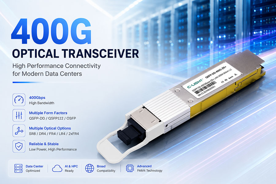
400G optical transceivers have become an important part of modern data center and high-speed Ethernet networks. As cloud computing, AI workloads, high-performance computing, and distributed applications generate more traffic, 400G connectivity provides a practical bandwidth level between widely deployed 100G and 200G solutions and newer 800G and 1.6T technologies.
This guide covers 400G optical transceiver technology, form factors, transmission architectures, PAM4 signaling, optical configurations, fiber types, applications, thermal considerations, and key factors to evaluate when selecting a 400G optical module.
1. What Is a 400G Optical Transceiver?
A 400G optical transceiver is a high-speed networking device that converts electrical data into optical signals for transmission over fiber and converts received optical signals back into electrical data.
A typical 400G optical transceiver provides an aggregate data rate of approximately 400 Gb/s. Depending on the module architecture, the 400G signal can be transmitted using multiple optical lanes and different wavelength configurations.
400G modules are used in applications ranging from data center switch-to-switch connections to high-performance computing and AI infrastructure. The exact module type depends on transmission distance, fiber infrastructure, switch interface, power requirements, and network architecture.
2. Why 400G Optical Transceivers Matter
400G provides a significant increase in bandwidth compared with earlier 100G and 200G generations while maintaining a pluggable optical architecture that can be integrated into modern network equipment.
Higher bandwidth: Provides up to 400 Gb/s aggregate data transmission.
Higher network density: Enables more bandwidth per switch port.
AI and HPC connectivity: Supports high-throughput connections within computing and networking environments.
Data center networking: Suitable for switch-to-switch and other high-capacity links.
Network evolution: Provides an established bandwidth level between 200G-class and newer 800G-class optical connectivity.
3. How Does a 400G Optical Transceiver Work?
A 400G optical transceiver contains electrical interfaces, optical transmit and receive components, signal-processing circuitry, monitoring functions, and thermal-management structures.
On the transmit side, electrical signals from the host switch are processed and converted into optical signals. These optical signals are transmitted through the connected fiber.
At the receiving end, photodetectors convert the optical signals back into electrical signals for processing by the host equipment.
The basic signal path can be summarized as:
Host switch sends high-speed electrical data.
The transceiver processes the electrical signals.
Optical components convert the electrical signals into optical signals.
Fiber carries the optical signals to the remote transceiver.
The receiving transceiver converts optical signals back into electrical data.
4. 400G PAM4 Technology
PAM4 is an important signaling technology used in modern high-speed Ethernet optical systems. Unlike NRZ signaling, which uses two signal levels, PAM4 uses four signal levels and can represent two bits per symbol.
PAM4 helps increase the data rate of each electrical or optical lane without requiring the symbol rate to increase by the same factor as the aggregate data rate.
However, PAM4 also introduces additional signal-integrity requirements. The smaller separation between signal levels makes parameters such as noise, jitter, insertion loss, return loss, and crosstalk increasingly important.
For this reason, 400G optical transceiver development involves both optical and high-speed electrical engineering.
5. 400G Optical Transceiver Form Factors
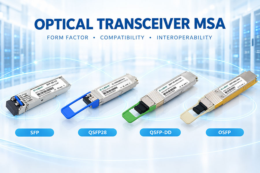
Several form factors have been used for 400G optical connectivity. The appropriate form factor depends on the host platform and the intended network architecture.
5.1 400G QSFP-DD
400G QSFP-DD Optical Transceiver | DR4 FR4 LR4 ZR Module丨C-LIGHT
QSFP-DD is a high-density pluggable form factor that can support high-speed electrical interfaces through multiple electrical lanes. 400G QSFP-DD modules are widely relevant to data center Ethernet applications.
The relatively compact form factor makes QSFP-DD attractive where port density and compatibility with existing high-density switch designs are important considerations.
5.2 400G OSFP
400G OSFP Optical Transceiver | SR8 DR4 FR4 400G Module丨C-LIGHT
OSFP is another important form factor for 400G and higher-speed optical networking. Its mechanical dimensions provide additional space that can be useful for thermal management and high-speed optical implementations.
400G OSFP modules are commonly considered for high-capacity data center and networking platforms that support the OSFP interface.
5.3 400G QSFP112
400G QSFP112 LR4/FR4/DR4/SR4 Optical Transceiver丨AI Data Center Networks丨C-LIGHT
QSFP112 is associated with high-speed four-lane electrical architectures. It can be used for 400G optical modules where each electrical lane operates at a higher data rate than earlier QSFP-based generations.
When selecting between QSFP-DD, QSFP112, and OSFP, compatibility with the host switch and the electrical interface is essential. These form factors should not be treated as interchangeable simply because they support the same aggregate 400G bandwidth.
6. Common 400G Optical Configurations
400G optical transceivers are available in different optical architectures. The choice is mainly determined by transmission distance, fiber type, optical budget, wavelength configuration, and the physical cabling environment.
6.1 400G SR8
400G SR8 is designed for short-reach applications and typically uses parallel multimode fiber transmission. An eight-lane optical architecture can be used to achieve the aggregate 400G data rate.
SR8 can be suitable for short connections inside data centers where multimode fiber infrastructure is available.
6.2 400G DR4
400G DR4 is a single-mode fiber architecture designed for data center links over substantially longer distances than typical multimode short-reach applications.
The architecture uses four optical lanes and is commonly associated with parallel single-mode fiber connectivity and MPO-based cabling.
6.3 400G FR4
400G FR4 uses multiple wavelengths over single-mode fiber to provide a 400G link. Wavelength multiplexing allows multiple optical channels to share the same fiber pair.
This architecture can simplify fiber connectivity compared with parallel-fiber configurations and is useful for data center applications requiring longer reach than typical multimode solutions.
6.4 400G LR4
400G LR4 is designed for longer-reach single-mode fiber applications. It uses wavelength-division multiplexing to transmit multiple optical channels over a duplex fiber connection.
Compared with short-reach configurations, LR4 applications place greater emphasis on optical power, receiver sensitivity, dispersion, link budget, and transmission performance.
6.5 400G 2xFR4
400G 2xFR4 uses a breakout-oriented architecture in which a 400G connection can be divided into two 200G optical connections under supported network configurations.
This type of architecture can provide additional flexibility when integrating 400G switch ports with lower-speed network interfaces.
7. 400G Single-Mode vs. Multimode Optical Transceivers
Fiber selection is one of the first considerations when choosing a 400G optical transceiver.
| Feature | Multimode 400G | Single-Mode 400G |
|---|---|---|
| Typical architecture | SR8 and similar short-reach configurations | DR4, FR4, LR4 and other configurations |
| Fiber | Multimode fiber | Single-mode fiber |
| Typical application | Short data center links | Longer data center and campus links |
| Connectivity | Often parallel fiber | Parallel or wavelength-multiplexed fiber |
| Distance | Short reach | Short to longer reach depending on module |
The actual transmission distance depends on the specific module specification, fiber quality, connectors, optical budget, and network conditions. The module datasheet should always be used when determining the supported reach.
8. 400G Optical Components
The optical engine is a critical part of a 400G transceiver. It contains the components required to generate, modulate, transmit, receive, and detect high-speed optical signals.
8.1 Laser Sources
Laser selection depends on the module architecture, wavelength, transmission distance, modulation method, and required optical power.
Short-reach multimode modules and longer-reach single-mode modules can use different optical component configurations because their transmission requirements are different.
8.2 Modulators
Optical modulation determines how electrical information is encoded onto the optical carrier. The implementation depends on the specific transceiver architecture and target application.
8.3 Photodetectors
Photodetectors convert received optical signals into electrical signals. Receiver bandwidth, sensitivity, responsivity, and noise characteristics all influence overall link performance.
9. 400G DSP and Signal Processing
Digital signal processing can play an important role in high-speed optical modules, particularly where advanced modulation and transmission impairments need to be managed.
DSP functions can include signal equalization, clock recovery, monitoring, and other signal-processing functions depending on the module architecture.
The use of high-speed DSP technology also contributes to module power consumption and thermal requirements, making system-level optimization important.
10. 400G Optical Module Power Consumption
Power consumption is an important consideration in high-density data centers. A switch may contain a large number of optical ports, meaning that even a relatively small difference in power per module can affect total system power.
Power consumption varies significantly between 400G transceiver types. Factors include optical architecture, DSP implementation, laser technology, transmission distance, temperature range, and module design.
When evaluating a 400G optical transceiver, power should therefore be considered together with transmission distance and required optical performance rather than as an isolated specification.
11. Thermal Management of 400G Optical Transceivers
As bandwidth increases, thermal management becomes increasingly important. Heat generated by high-speed electrical components, optical devices, and signal-processing circuits must be transferred away from the module efficiently.
Common thermal-management considerations include:
Heat spreader design
Thermal interface materials
Module component placement
Switch airflow
Operating temperature
Rack-level cooling architecture
Good thermal management helps maintain stable optical and electrical performance and can contribute to long-term module reliability.
12. 400G Optical Connectivity and Fiber Interfaces
400G modules can use different optical connector configurations depending on the optical architecture.
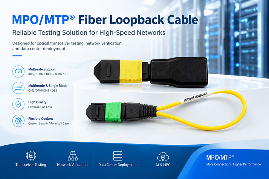
Parallel optical modules such as many SR8 and DR4 implementations can use MPO/MTP-style multi-fiber connectivity. Wavelength-multiplexed duplex solutions such as FR4 and LR4 can use duplex LC connectivity.
Connector selection should match the module's optical interface and the installed fiber infrastructure. Incorrect fiber type, polarity, connector configuration, or optical loss can prevent a link from operating correctly.
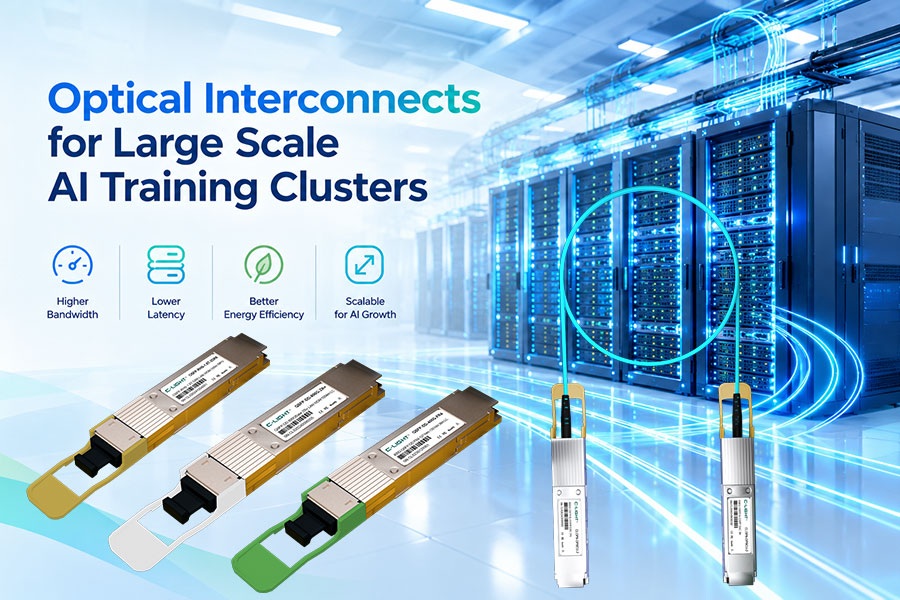
13. 400G Optical Transceivers for AI Data Centers
AI and high-performance computing environments require high-bandwidth connections between computing accelerators, switches, and network fabrics.
400G optical transceivers can be used in different parts of these networks depending on the switch generation, topology, required link distance, and bandwidth requirements.
In some deployments, 400G can provide a practical balance between bandwidth, power, port density, and deployment cost. At the same time, newer network platforms are moving toward 800G and 1.6T connectivity for applications requiring higher bandwidth per port.
14. 400G Optical Transceivers in Data Center Networks
400G optical modules can be deployed in several network configurations.
Switch-to-switch: High-capacity connections between leaf, spine, and other switching layers.
Data center interconnect: High-speed connections between network locations where supported by the required optical reach.
AI and HPC networks: High-bandwidth connectivity for computing and switching infrastructure.
Cloud infrastructure: High-density optical connections within large-scale data centers.
Network upgrades: Migration from lower-speed Ethernet interfaces to 400G connectivity.
15. 400G vs. 200G Optical Transceivers
400G provides twice the aggregate bandwidth of 200G and can increase bandwidth density when supported by the network equipment.
| Feature | 200G | 400G |
|---|---|---|
| Aggregate bandwidth | 200 Gb/s | 400 Gb/s |
| Typical applications | Data center and Ethernet networks | Higher-capacity data center and Ethernet networks |
| Signal technology | Depends on implementation | PAM4 widely used in modern implementations |
| Port density | Lower bandwidth per port | Higher bandwidth per port |
16. 400G vs. 800G Optical Transceivers
400G and 800G serve different stages of high-speed network evolution. 400G remains relevant for many current network deployments, while 800G is designed for newer platforms that require greater bandwidth per port.
The choice should be based on the capabilities of the network switch, required bandwidth, optical infrastructure, power budget, and deployment requirements.
| Feature | 400G | 800G |
|---|---|---|
| Aggregate bandwidth | 400 Gb/s | 800 Gb/s |
| Network role | High-speed data center connectivity | Next-generation high-bandwidth connectivity |
| Common form factors | QSFP-DD, QSFP112, OSFP | OSFP, QSFP-DD800 and other supported architectures |
| Power and thermal requirements | High | Generally more demanding |
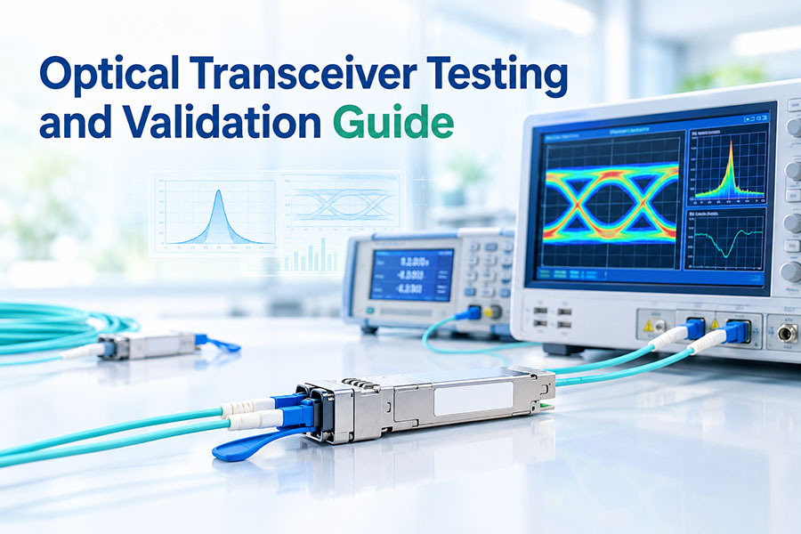
17. 400G Optical Transceiver Testing
Testing is essential for validating 400G optical module performance and interoperability.
17.1 Electrical Testing
Electrical validation can include eye diagrams, insertion loss, return loss, crosstalk, jitter, and other high-speed signal-integrity measurements.
17.2 Optical Testing
Optical testing can include transmit optical power, receiver sensitivity, wavelength characteristics, extinction ratio, optical modulation amplitude, and other parameters specified by the applicable module design.
17.3 BER Testing
Bit error rate testing is used to evaluate transmission performance under defined test conditions. High-speed optical systems can use appropriate PRBS patterns and test procedures to validate link performance.
17.4 Environmental Testing
Environmental qualification can evaluate module operation across specified temperature, humidity, vibration, and other operating conditions.
17.5 Compatibility Testing
Compatibility testing verifies that the optical transceiver operates correctly with the intended switch, network equipment, fiber, connectors, and cabling system.
18. Key Factors When Selecting a 400G Optical Transceiver
The correct 400G module should be selected according to the complete network environment.
Form factor: Verify QSFP-DD, QSFP112, OSFP, or another supported interface.
Transmission distance: Select SR, DR, FR, LR, or another architecture according to the required reach.
Fiber type: Confirm multimode or single-mode fiber requirements.
Connector: Verify LC, MPO/MTP, or other optical interfaces.
Wavelength: Check the wavelength configuration required by the optical link.
Power consumption: Confirm that the module fits within the switch and rack power budget.
Thermal environment: Evaluate airflow and operating temperature.
Host compatibility: Confirm compatibility with the intended switch or network platform.
Optical budget: Ensure the module provides sufficient link performance for the complete fiber path.
19. C-LIGHT 400G Optical Transceiver Solutions
C-LIGHT provides optical transceiver solutions covering multiple data rates and optical networking applications. Its 400G portfolio can support different host interfaces, transmission architectures, and data center connectivity requirements.
Depending on the application, 400G solutions can include QSFP-DD, QSFP112, and OSFP-based designs, as well as optical configurations for short-reach and longer-reach single-mode fiber applications.
For a specific C-LIGHT 400G optical transceiver, users should refer to the corresponding product specification to confirm transmission distance, wavelength, optical connector, power consumption, operating temperature, and host compatibility.
20. Future Development of 400G Optical Transceivers
Although the industry is moving toward 800G and 1.6T connectivity, 400G optical transceivers are expected to remain important in networks where their bandwidth and deployment characteristics match system requirements.
Future development will focus on improving power efficiency, optical integration, signal integrity, thermal performance, interoperability, and manufacturing efficiency.
400G can also serve as an important migration point for network operators moving from 100G and 200G toward higher-speed optical connectivity. Different network layers may adopt different speeds rather than upgrading every connection to the newest generation simultaneously.
21. Conclusion
400G optical transceivers provide a practical high-speed connectivity solution for modern data centers, Ethernet networks, AI infrastructure, and high-performance computing environments.
The 400G ecosystem includes multiple form factors and optical architectures, including QSFP-DD, QSFP112, OSFP, SR8, DR4, FR4, LR4, and 2xFR4 configurations. Each solution addresses different requirements for transmission distance, fiber type, connector configuration, bandwidth density, and system design.
As 800G and 1.6T optical technologies continue to develop, 400G remains an important part of the broader optical networking roadmap. Selecting the appropriate module requires consideration of the complete network rather than bandwidth alone.
22.Frequently Asked Questions About 400G Optical Transceivers
Q1:What is a 400G optical transceiver?
Answer: A 400G optical transceiver is a high-speed optical module designed to provide an aggregate data rate of approximately 400 Gb/s over optical fiber.
Q2:What is PAM4 in a 400G optical transceiver?
Answer: PAM4 is a four-level pulse amplitude modulation technology that can represent two bits per symbol. It is widely used in modern high-speed Ethernet architectures to increase lane data rates.
Q3:What are the common 400G optical transceiver form factors?
Answer: Common form factors include QSFP-DD, QSFP112, and OSFP. The appropriate form factor depends on the host switch and its supported electrical and mechanical interfaces.
Q4:What is the difference between 400G SR8 and 400G DR4?
Answer: 400G SR8 is generally designed for short-reach multimode fiber applications, while 400G DR4 is designed for single-mode fiber applications and longer transmission distances. The exact supported reach depends on the module specification and fiber system.
Q5:What fiber is used for 400G optical transceivers?
Answer: Both multimode and single-mode fiber can be used. SR-type modules are generally associated with multimode fiber, while DR, FR, and LR configurations commonly use single-mode fiber.
Q6:What is the difference between 400G FR4 and LR4?
Answer: Both use wavelength-multiplexed optical transmission over single-mode fiber, but they target different transmission distances and optical link requirements. The specific reach and optical budget should be checked in the applicable module specification.
Q7:Are 400G optical transceivers suitable for AI data centers?
Answer: Yes. 400G optical transceivers can be used in AI and high-performance computing networks where 400G bandwidth is supported by the switch and network architecture.
Q8:Is 400G being replaced by 800G?
Answer: 800G is the next higher bandwidth level for many emerging network platforms, but this does not mean that 400G becomes unsuitable for every application. 400G remains appropriate where its bandwidth, reach, power, and cost characteristics meet network requirements.
Q9:Does C-LIGHT provide 400G optical transceivers?
Answer: Yes. C-LIGHT provides 400G optical transceiver solutions for high-speed data center and networking applications, with different form factors and optical configurations available according to application requirements.
23.Summary
400G optical transceivers play an important role in the evolution of high-speed optical networking. Their combination of high bandwidth, multiple form factors, and flexible optical architectures makes them suitable for a broad range of data center and Ethernet applications.
When selecting a 400G optical module, transmission distance, fiber type, optical architecture, connector, host compatibility, power consumption, thermal conditions, and optical link budget should all be evaluated together. This approach helps ensure that the selected transceiver matches the requirements of the complete network.
 >
>

 >
>
 >
>
 >
>
 >
>
 >
>
 >
>
 >
>