TEL:+86 132 6656 7067




The 100G QSFP28 BIDI ZR4 is a single-fiber bidirectional optical transceiver that delivers 100Gbps over distances up to 80 kilometers on standard single-mode fiber. It combines LAN-WDM EML transmitters with SOA-assisted PIN receivers in a hot-pluggable QSFP28 package, using a simplex LC connector.
The module is designed for metro long-haul networks, data center interconnect, 5G transport, and fiber-constrained deployments where a single fiber must carry the full duplex 100G link.
Unlike conventional 100G LR4 or ER4 modules that require a duplex fiber pair, the BIDI ZR4 uses one fiber for both transmit and receive. This halves the fiber count per link and makes the module attractive where fiber is scarce, expensive to lease, or already fully occupied. The trade-off is a more complex optical architecture and a stricter pairing requirement: a BIDI ZR4 Side A module must be paired with a BIDI ZR4 Side B module at the opposite end of the link.

1. Product Overview
The CL100GQBD80-B is C-LIGHT's 100G QSFP28 BIDI ZR4 transceiver, designed for 103.125Gbps point-to-point Ethernet links over single-mode fiber. It is compliant with the QSFP28 standard (SFF-8661 Rev 2.5, SFF-8636 Rev 2.10a) and the CAUI-4 electrical interface defined in IEEE 802.3bm-2015[reference:0]. The module operates from a single 3.3V supply and dissipates 4.5W at 55°C case temperature and 6.5W at 70°C case temperature.
The optical architecture combines four LAN-WDM EML transmitters with four SOA+PIN receivers. The transmitters are cooled EML lasers, and the receivers use a semiconductor optical amplifier integrated with a PIN photodiode. This combination provides the receiver sensitivity required for 80km reach: -28dBm in OMA with KR4 FEC enabled in the host.
| Parameter | Specification |
|---|---|
| Form Factor | QSFP28, hot-pluggable |
| Data Rate | 103.125 Gbps aggregate |
| Reach | Up to 80 km over G.652 SMF |
| Connector | Simplex LC |
| Transmitter | 4 × LAN-WDM EML, cooled |
| Receiver | 4 × SOA + PIN, cooled |
| Receiver Sensitivity | -28 dBm (OMA, with KR4 FEC) |
| Power Dissipation | 4.5 W at 55°C, 6.5 W at 70°C |
| Supply Voltage | 3.3 V |
| Case Operating Temperature | 0°C to 70°C |
| Management | DDM/DCM via two-wire serial interface |
| Compliance | RoHS (EU 2011/65/EU), Class 1 Laser |
2. Wavelength Plan and Side A / Side B Pairing
The BIDI ZR4 uses two complementary wavelength sets, one for each direction. The Side A module transmits on the LAN-WDM grid around 1310 nm and receives around 1290 nm. The Side B module does the reverse: it transmits around 1290 nm and receives around 1310 nm. The two modules must be paired for the link to operate.
2.1 Transmit Wavelengths (Side A)
The Side A transmitter uses four LAN-WDM channels: 1295 nm, 1300 nm, 1304 nm, and 1309 nm. These fall within the LAN-WDM grid defined in IEEE 802.3ba.
2.2 Receive Wavelengths (Side A)
The Side A receiver detects four LAN-WDM channels: 1273 nm, 1277 nm, 1282 nm, and 1286 nm. The Side B module transmits on these wavelengths and receives on the Side A transmit wavelengths.
| Module | Transmit Wavelengths | Receive Wavelengths |
|---|---|---|
| Side A (CL100GQBD80-A) | 1295 / 1300 / 1304 / 1309 nm | 1273 / 1277 / 1282 / 1286 nm |
| Side B (CL100GQBD80-B) | 1273 / 1277 / 1282 / 1286 nm | 1295 / 1300 / 1304 / 1309 nm |
The wavelength separation between the transmit and receive bands is approximately 20 nm, which allows the internal WDM filters to separate the two directions with high isolation. This separation is what enables single-fiber bidirectional operation: the receiver in each module blocks the transmitted wavelength and passes only the received wavelength.
3. Optical Specifications
The optical performance of the BIDI ZR4 is shaped by the LAN-WDM EML transmitters and the SOA+PIN receivers. The specifications below are for the Side A module; the Side B module has mirrored values.
3.1 Transmitter Specifications
| Parameter | Min | Typical | Max | Unit |
|---|---|---|---|---|
| Wavelength L0 | 1294.80 | 1295 | 1296.49 | nm |
| Wavelength L1 | 1299.29 | 1300 | 1300.09 | nm |
| Wavelength L2 | 1303.81 | 1304 | 1305.53 | nm |
| Wavelength L3 | 1308.36 | 1309 | 1310.09 | nm |
| Side-Mode Suppression Ratio | 30 | — | — | dB |
| Average Launch Power (per lane) | 2 | — | 6.5 | dBm |
| Total Average Launch Power | — | — | 12.5 | dBm |
| Extinction Ratio | 8 | — | — | dB |
| Optical Modulation Amplitude (per lane) | 0 | — | 6.5 | dBm |
| Optical Return Loss Tolerance | — | — | 20 | dB |
| Transmitter Reflectance | — | — | -12 | dB |
3.2 Receiver Specifications
| Parameter | Min | Typical | Max | Unit |
|---|---|---|---|---|
| Wavelength L0 | 1272.51 | 1273 | 1274.58 | nm |
| Wavelength L1 | 1276.86 | 1277 | 1278.93 | nm |
| Wavelength L2 | 1281.21 | 1282 | 1283.31 | nm |
| Wavelength L3 | 1285.61 | 1286 | 1287.71 | nm |
| Receiver Sensitivity (OMA, per lane) | — | -28 | — | dBm |
| Stressed Receiver Sensitivity (OMA) | — | — | -27 | dBm |
| Saturation Power (per lane) | — | -4.5 | — | dBm |
The receiver sensitivity of -28 dBm in OMA is achieved with KR4 FEC enabled in the host. Without FEC, the module supports approximately 40km reach; with KR4 FEC, the reach extends to 80km. The SOA in front of the PIN photodiode provides the additional gain needed to detect the weak signal after 80km of fiber loss.
4. How KR4 FEC Extends Reach to 80km
Forward error correction is essential for the 80km reach of the BIDI ZR4. The module operates at 103.125Gbps aggregate, with four lanes of approximately 25.78Gbps each.
At this rate, the receiver sensitivity without FEC is not sufficient to close an 80km link with adequate margin. KR4 FEC, defined in IEEE 802.3, adds redundancy to the data stream at the host level. The receiver detects and corrects errors introduced by the 80km fiber span, including attenuation, dispersion, and noise from the SOA.
The host must support KR4 FEC for the module to achieve 80km reach. The module itself does not contain the FEC encoder or decoder; it is the host ASIC or FPGA that applies the FEC.
The module specification explicitly states that the -28dBm sensitivity is achieved "with enabled KR4 FEC in host". Deployments must confirm that the switch, router, or NIC port supports KR4 FEC before planning an 80km link with this module.
| Condition | Reach |
|---|---|
| KR4 FEC disabled | Approximately 40 km |
| KR4 FEC enabled in host | Up to 80 km |
5. Applications
The BIDI ZR4 is designed for scenarios where 100G capacity must be delivered over long distances with minimal fiber. Its applications cluster around metro and regional transport, data center interconnect, and 5G backhaul.
5.1 Data Center Interconnect (DCI)
DCI links connect separate data centers within a metropolitan area or between nearby cities. Distances of 40 to 80 kilometers are common. The BIDI ZR4 delivers 100G over a single fiber pair, which is valuable when fiber is leased or scarce. In a conventional 100G LR4 deployment, each 100G link consumes two fibers (one transmit, one receive). The BIDI ZR4 consumes one fiber, halving the fiber count for the same capacity.
5.2 Metro Long-Haul Networks
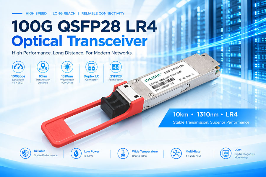
Metro networks connect central offices, carrier hotels, and aggregation sites across a city. The 80km reach of the BIDI ZR4 covers the span between a metro core node and a regional aggregation point without intermediate regeneration. The module is suitable for 5G transport and backbone links where 100G capacity is required over distances that exceed the 10km reach of LR4.
5.3 Fiber-Constrained Deployments
In environments where fiber is scarce, expensive to lease, or fully occupied, the BIDI ZR4 allows capacity to be added without pulling new fiber. The single-fiber operation means that a fiber pair that previously carried one 100G duplex link can carry two 100G BIDI links, doubling the capacity of the existing fiber plant. This is particularly valuable in legacy network upgrades and in leased-fiber scenarios where the recurring cost is per fiber strand.
5.4 5G Aggregation and Backhaul
5G networks require high-capacity backhaul between base stations and the core. The BIDI ZR4 provides 100G over distances up to 80km, making it suitable for 5G aggregation layer backhaul where fiber to each site is limited.
| Application | Typical Distance | BIDI ZR4 Fit |
|---|---|---|
| Data Center Interconnect | 40–80 km | Primary |
| Metro Long-Haul | 40–80 km | Primary |
| 5G Aggregation Backhaul | Up to 80 km | Primary |
| Fiber-Constrained DCI | Up to 80 km | Primary |
| Enterprise Private Network | Up to 80 km | Possible |
6. BIDI ZR4 vs 100G LR4
The most common comparison for the BIDI ZR4 is the 100G LR4, the standard 10km 100G interface. The two modules serve different segments of the distance and fiber-count spectrum.
| Parameter | 100G LR4 | 100G BIDI ZR4 |
|---|---|---|
| Reach | 10 km | 80 km |
| Fiber Count per Link | 2 fibers (duplex) | 1 fiber (simplex) |
| Connector | Duplex LC | Simplex LC |
| Transmitter | 4 × CWDM EML around 1310 nm | 4 × LAN-WDM EML around 1310 nm |
| Receiver | 4 × PIN | 4 × SOA + PIN |
| Receiver Sensitivity | Approximately -10 dBm | -28 dBm (OMA, with KR4 FEC) |
| FEC Requirement | RS-FEC typically | KR4 FEC mandatory for 80km |
| Power Consumption | 3.5–4.0 W typical | 4.5–6.5 W |
| Primary Application | Campus, intra-metro | Metro DCI, 5G backhaul, fiber-constrained |
The LR4 is the default for links under 10km where duplex fiber is available. The BIDI ZR4 is the appropriate choice when the link exceeds 10km, when only one fiber is available, or when the fiber count must be minimized. The two modules do not compete for the same link: the distance and the fiber availability determine which one is deployed.
7. Deployment Considerations
Deploying the BIDI ZR4 requires attention to pairing, FEC configuration, optical budget, and connector cleanliness.
7.1 Side A / Side B Pairing
The BIDI ZR4 must be deployed in matched pairs. A Side A module at one end requires a Side B module at the other end. Deploying two Side A modules on the same link will not work, because both will transmit on the same wavelengths and both will receive on the same wavelengths. The link will not come up. The modules should be ordered, stocked, and labeled as matched pairs to avoid this error.
7.2 KR4 FEC Configuration
The host port must be configured for KR4 FEC. If FEC is disabled, the link may come up at 40km but will fail at 80km. The switch, router, or NIC documentation should be checked to confirm KR4 FEC support and the procedure for enabling it. The FEC configuration must match at both ends of the link.
7.3 Optical Budget
An 80km link at 1310 nm consumes approximately 28 dB of fiber loss (0.35 dB/km). The transmitter launches 2 to 6.5 dBm per lane, and the receiver sensitivity is -28 dBm in OMA. The optical budget must close with margin for connectors, splices, and aging. The link should be engineered with the actual fiber attenuation and connector count, not assumed values. The SOA in the receiver provides additional gain, but it also adds noise; the link margin should account for the SOA noise figure.
7.4 Connector Cleanliness
The simplex LC connector must be cleaned and inspected before mating. Contamination on the endface can block a significant fraction of the optical power and degrade the receiver sensitivity. In an 80km link where the margin is tight, a contaminated connector can cause link failure. Inspection with a video probe is recommended before every mating.
7.5 Thermal Management
The module dissipates 4.5W at 55°C and 6.5W at 70°C case temperature. In a high-density switch chassis, the thermal load of multiple BIDI ZR4 modules must be included in the cooling design. The case temperature must remain below 70°C for the module to operate within specification.
8. Summary
The 100G QSFP28 BIDI ZR4 is a single-fiber bidirectional transceiver that delivers 100Gbps over 80km of standard single-mode fiber. It uses LAN-WDM EML transmitters and SOA+PIN receivers to achieve the required link budget, and it relies on KR4 FEC in the host to close the 80km span. The module consumes 4.5W at 55°C and 6.5W at 70°C, operates from a 3.3V supply, and supports DDM/DCM diagnostics.
The BIDI ZR4 is deployed in matched Side A / Side B pairs. The two modules use complementary wavelength sets, with approximately 20 nm separation between the transmit and receive bands. This separation allows a single fiber to carry bidirectional 100G traffic with sufficient isolation between directions.
The primary applications are data center interconnect, metro long-haul, 5G backhaul, and fiber-constrained deployments where the fiber count per link must be minimized. The module does not replace the 100G LR4 for short-reach links under 10km where duplex fiber is available; it complements the LR4 for longer reaches and for environments where fiber is scarce. Deployment requires attention to pairing, FEC configuration, optical budget, and connector cleanliness.
 >
>

 >
>
 >
>
 >
>
 >
>
 >
>
 >
>
 >
>