TEL:+86 132 6656 7067




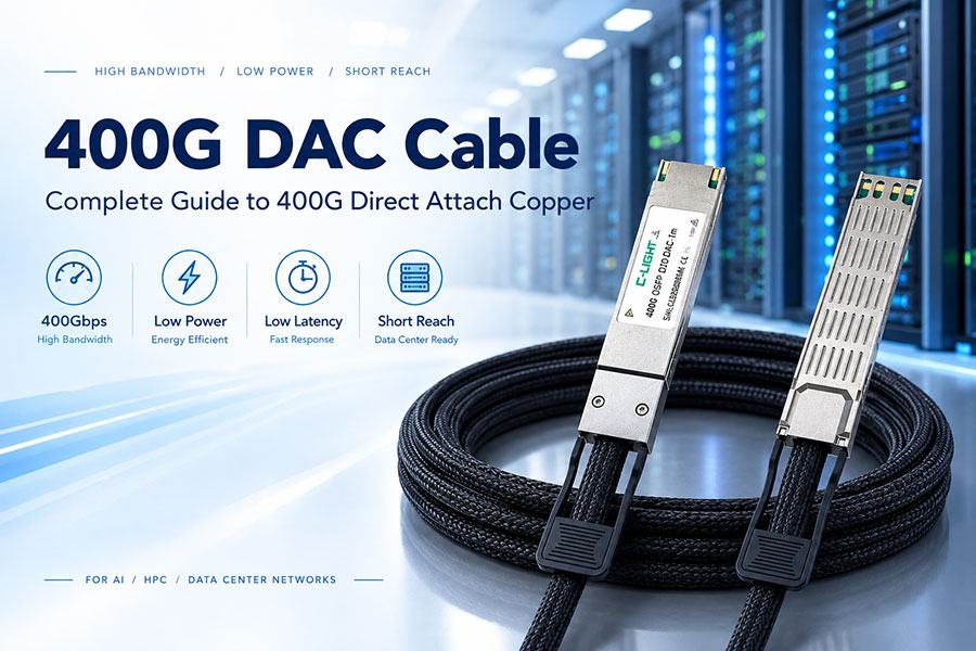
400G DAC transmission distance is typically limited to a few meters, making it suitable for short, high-bandwidth connections inside data centers, AI clusters, and high-performance computing systems. The actual reach depends on cable design, lane speed, connector type, gauge, signal integrity, and whether the DAC is passive or active.
1. What Is 400G DAC Transmission Distance?
400G DAC transmission distance refers to the maximum practical cable length over which a 400Gbps Direct Attach Copper connection can maintain reliable electrical signal transmission between compatible network ports.
Unlike optical transceivers that convert electrical signals into light, a DAC keeps the signal in the electrical domain and uses copper conductors between two integrated high-speed connectors.
2. What Is the Typical Distance of a 400G DAC?
Most 400G DAC products are designed for very short-reach connections. Typical commercial configurations cover approximately 0.5m to 3m, while some high-speed configurations have a shorter maximum length depending on the electrical interface.
For C-LIGHT 400G DAC, the general portfolio covers 0.5m to 3m, while selected QSFP112 and OSFP112 configurations are specified for 0.5m to 2m.
3. Why Is 400G DAC Distance So Short?
400G transmission uses extremely high electrical signaling rates. In common PAM4 architectures, 400Gbps can be implemented using eight 50Gbps electrical lanes. At these speeds, copper channels experience insertion loss, return loss, crosstalk, attenuation, impedance discontinuities, and other signal-integrity limitations.
As cable length increases, these electrical impairments become more difficult to compensate while maintaining acceptable eye quality and bit-error performance.
4. 400G DAC Distance Compared With Optical Solutions
| Solution | Typical Reach | Transmission Medium | Typical Use |
| 400G DAC | 0.5–3m | Copper | Intra-rack and short connections |
| 400G AEC | Several meters | Copper with active electronics | Longer copper interconnects |
| 400G AOC | Up to tens of meters | Multimode optical fiber | Rack-to-rack and longer short-reach links |
| 400G DR4 | Up to about 500m | Single-mode fiber | Data center optical links |
| 400G FR4 | Up to about 2km | Single-mode fiber | Longer data center connections |
5. 0.5m, 1m, 2m and 3m 400G DAC Cables
400G DAC cables are commonly offered in several short lengths to match rack layout and port-to-port distance.
0.5m: Suitable for very short connections between adjacent equipment or tightly positioned ports.
1m: Common for switch-to-server or switch-to-GPU connections within the same rack.
2m: Useful when equipment is separated vertically or horizontally inside a rack.
3m: Appropriate for longer intra-rack routing or very closely positioned racks when supported by the specific DAC design.
6. 400G DAC 2m vs 3m
The difference between a 2m and 3m DAC is not only physical length. The additional meter increases electrical channel loss and can reduce the available signal margin.
A 3m DAC should therefore be selected according to the cable's validated electrical performance rather than simply assuming that a 2m design can always be extended to 3m.
7. Is 400G DAC Available in 5m?
Passive 400G DAC is generally optimized for shorter lengths, and 5m is beyond the common range of many passive designs. When a copper connection needs to extend farther, an active electrical solution such as an AEC may be more appropriate.
The exact maximum length should always be checked against the specific vendor part number and host platform.
8. Passive 400G DAC Distance
A passive DAC contains copper conductors and integrated connectors without active signal-conditioning electronics in the cable assembly. Because the signal is not regenerated inside the cable, transmission performance becomes increasingly difficult to maintain as the cable gets longer.
This is why passive 400G DAC products are normally concentrated around short lengths such as 0.5m, 1m, 2m, and 3m.
9. Active Copper and 400G AEC Distance
An AEC uses active electronics to condition or retime the electrical signal, allowing copper connectivity to extend farther than many passive DAC implementations.
For installations where 400G copper connectivity must go beyond the practical range of a passive DAC, an AEC can provide a useful intermediate solution before moving to optical cabling.
10. What Determines 400G DAC Transmission Distance?
Several factors determine the usable distance of a 400G DAC:
Copper conductor design and cable gauge
Host electrical interface and signaling rate
Connector and PCB insertion loss
Return loss and impedance matching
Near-end and far-end crosstalk
DSP, equalization, or retimer capability
Operating temperature
Required BER and link margin
Switch, NIC, GPU or server compatibility
11. Cable Gauge and 400G DAC Reach
Copper cable gauge affects electrical resistance, attenuation, mechanical flexibility, and thermal behavior. C-LIGHT 400G DAC products use configurations such as 28AWG and 30AWG depending on the cable and breakout architecture.
A thinner cable can improve routing flexibility, but electrical performance must remain within the requirements of the target high-speed interface.
12. PAM4 and 400G DAC Transmission Distance
Many 400G electrical interfaces use PAM4 signaling to increase the amount of data transmitted per lane. PAM4 carries four signal levels, allowing two bits per symbol.
The higher signaling efficiency also makes the link more sensitive to noise, distortion, loss, and signal-quality degradation than lower-speed NRZ links. Consequently, 400G DAC distance is strongly connected to high-speed signal integrity.
13. Signal Loss Becomes More Important as Distance Increases
As a copper cable becomes longer, attenuation increases. High-frequency components are especially affected, which can distort the waveform arriving at the receiver.
The system must compensate for this degradation through transmitter equalization, receiver equalization, retiming, or other signal-conditioning techniques. When the required compensation becomes too large, an optical solution may provide a better link margin.
14. 400G DAC Transmission Distance and BER
Bit error rate is one of the most important indicators of whether a 400G link is operating correctly. A cable that physically reaches the destination is not necessarily a successful 400G link if the electrical signal quality is insufficient.
Longer DAC assemblies must maintain adequate signal quality after accounting for insertion loss, crosstalk, reflections, temperature changes, and host-channel losses.
15. Host Channel Matters More Than Cable Length Alone
The DAC is only one part of the complete electrical channel. The total path can include the switch ASIC, connector, PCB traces, port structure, DAC connector, copper cable, and receiving device.
For this reason, a 3m DAC that works in one platform may not provide the same margin in another platform with different PCB losses or equalization characteristics.
16. 400G DAC Distance in AI Data Centers
AI data centers commonly place GPU servers, high-speed switches, network adapters, and accelerator infrastructure in dense racks. These architectures often create short physical connections, making DAC an attractive solution when the distance remains within the supported range.
For very short GPU-to-switch and server-to-switch connections, DAC can provide high bandwidth with low cable complexity.
17. 400G DAC for GPU-to-Switch Connections
Modern AI clusters can require hundreds or thousands of high-speed electrical connections. When GPU servers and switches are physically close, short 400G DAC assemblies can reduce the need for optical conversion.
The main design requirement is to keep the physical topology within the validated DAC reach and electrical margin of the equipment.
18. 400G DAC for InfiniBand
400G DAC is also used in high-performance InfiniBand environments where short-reach, high-bandwidth interconnects are required between compute and networking equipment.
C-LIGHT's 400G DAC portfolio includes configurations designed for InfiniBand environments and supports direct 400G as well as selected breakout architectures.
19. 400G DAC for Ethernet
For Ethernet, 400G DAC can be used for short connections between compatible switches, servers, network adapters, and other high-speed data center equipment.
QSFP-DD, QSFP112, OSFP112, and OSFP56 are among the interface families used in different 400G DAC implementations.
20. 400G DAC Breakout Cable Distance
400G DAC is not limited to straight-through 400G-to-400G connections. Breakout configurations can divide a 400G port into lower-speed connections such as 2x200G, 4x100G, or 8x50G depending on the interface and product design.
Breakout cables should be evaluated as complete assemblies because connector count, branch structure, lane mapping, and cable construction can influence electrical performance.
21. QSFP112 400G DAC Distance
QSFP112-based 400G DAC designs are intended for high-speed electrical connectivity and can be offered in short lengths such as 0.5m to 2m depending on the configuration.
QSFP112 is particularly relevant to newer 400G and next-generation data center architectures where higher electrical lane speeds are required.
22. OSFP112 400G DAC Distance
OSFP112 provides another high-speed platform for 400G copper connectivity. Selected OSFP112 DAC configurations are typically designed for short lengths, such as 0.5m to 2m.
The larger OSFP family also provides significant thermal and mechanical options for high-speed networking equipment, but the physical form factor does not by itself determine cable reach.
23. OSFP56 400G DAC Distance
OSFP56-based 400G DAC can support short-reach connectivity in data center and InfiniBand environments. C-LIGHT lists configurations extending to approximately 3m for selected OSFP56 designs.
The supported distance remains dependent on the exact electrical implementation and host equipment.
24. QSFP-DD 400G DAC Distance
QSFP-DD is widely used for high-density 400G networking. C-LIGHT lists direct 400G QSFP-DD DAC configurations from approximately 0.5m to 3m, along with breakout options.
This makes QSFP-DD DAC suitable for short switch-to-server, switch-to-switch, and data center rack connections where optical reach is unnecessary.
25. 400G DAC vs 400G AOC for Distance
The main difference is the transmission medium. DAC uses copper and is optimized for very short distances, while AOC converts electrical signals into optical signals and uses fiber for longer short-reach connections.
Feature | 400G DAC | 400G AOC |
| Medium | Copper | Optical fiber |
| Typical distance | 0.5–3m | Typically longer than DAC |
| Power | Very low for passive DAC | Higher due to optical conversion |
| Latency | Very low | Low |
| Best use | Short intra-rack links | Longer short-reach links |
26. 400G DAC vs 400G AEC for Longer Copper Links
When copper is preferred but a passive DAC does not provide enough reach, an AEC can bridge the distance gap by using active signal conditioning.
This creates a practical deployment path:
Passive DAC → Active Copper/AEC → Optical AOC or Transceiver
The appropriate point in this transition depends on distance, power budget, latency requirements, thermal limits, cable management, and overall system cost.
27. Can 400G DAC Reach 10m?
A standard passive 400G DAC should not be assumed to support 10m. At this distance, the electrical loss and signal-integrity requirements become significantly more difficult for a passive copper connection.
For approximately 10m or longer, active copper or optical connectivity is generally more appropriate than a conventional passive 400G DAC.
28. What Happens When a 400G DAC Is Too Long?
An excessively long DAC can produce increased insertion loss, eye closure, increased jitter, crosstalk, and degraded receiver margin. The result can be an unstable link, increased error rate, or failure to establish the expected 400G connection.
Increasing the cable length is therefore not simply a mechanical decision. It changes the electrical characteristics of the complete link.
29. How to Choose the Correct 400G DAC Length
The correct cable length should be the shortest practical length that provides the required routing path without creating excessive slack or mechanical stress.
For a typical rack deployment, measure the actual port-to-port path rather than selecting cable length based only on rack height. A 1m or 2m DAC may be preferable to a 3m DAC when the equipment can be positioned closer together.
30. 400G DAC Distance and Thermal Conditions
Temperature can affect electrical characteristics such as conductor resistance and high-speed signal performance. High-density AI systems can also operate under demanding thermal conditions.
For this reason, cable qualification should consider the specified operating temperature range rather than testing only at room temperature.
31. 400G DAC Distance and Compatibility
A physically compatible connector does not guarantee that a 400G DAC will operate correctly in every switch, NIC, GPU system, or server.
Host-side electrical requirements, firmware, port configuration, coding, cable EEPROM information, and vendor interoperability can all affect deployment. Compatibility testing is particularly important in multi-vendor data center environments.
32. C-LIGHT 400G DAC Transmission Distance
C-LIGHT's 400G DAC product family is designed for short-distance high-speed connectivity and covers QSFP112, OSFP112, OSFP56, and QSFP-DD platforms.
400G DAC Configuration | Listed Distance | Cable |
| QSFP112 to QSFP112 | 0.5–2m | Copper, 28AWG |
| OSFP112 to OSFP112 | 0.5–2m | Copper, 28AWG |
| OSFP56 to OSFP56 | 0.5–3m | Copper, 28AWG |
| QSFP-DD to QSFP-DD | 0.5–3m | Copper, 28AWG |
33. Is 3m the Maximum for Every 400G DAC?
No. There is no single universal maximum length for every 400G DAC. Different implementations can have different limits based on lane rate, connector architecture, cable construction, active components, and host electrical specifications.
For this reason, the correct approach is to check the exact product specification instead of applying one distance value to all 400G DAC cables.
34. 400G DAC Distance Selection Guide
| Required Connection | Preferred Solution | Typical Consideration |
| Same rack, very short path | 400G DAC | 0.5–1m |
| Same rack, moderate routing | 400G DAC | 1–2m |
| Longer intra-rack path | 400G DAC or AEC | Check signal margin |
| Several meters with copper preference | AEC | Active signal conditioning |
| 10m-class short reach | AOC | Optical transmission |
| Hundreds of meters | Optical transceiver | DR4 or similar |
| Kilometer-scale link | Optical transceiver | FR4 or longer-reach optics |
35. 400G DAC Distance: Key Takeaways
400G DAC is primarily a short-reach connectivity solution. The most common product range is around 0.5m to 3m, with some high-speed QSFP112 and OSFP112 configurations limited to approximately 2m.
For the shortest intra-rack connections, passive DAC can provide a simple, low-power, low-latency option. When the required copper distance increases, AEC can provide additional electrical conditioning, while AOC and optical transceivers become better choices for longer links.
The most important rule is to select the cable according to the exact host platform, interface, cable construction, and validated distance specification rather than assuming that every 400G DAC supports the same reach.
 >
>

 >
>
 >
>
 >
>
 >
>
 >
>
 >
>
 >
>