TEL:+86 158 1857 3751


1. What Is a 2.5G CSFP Optical Module?
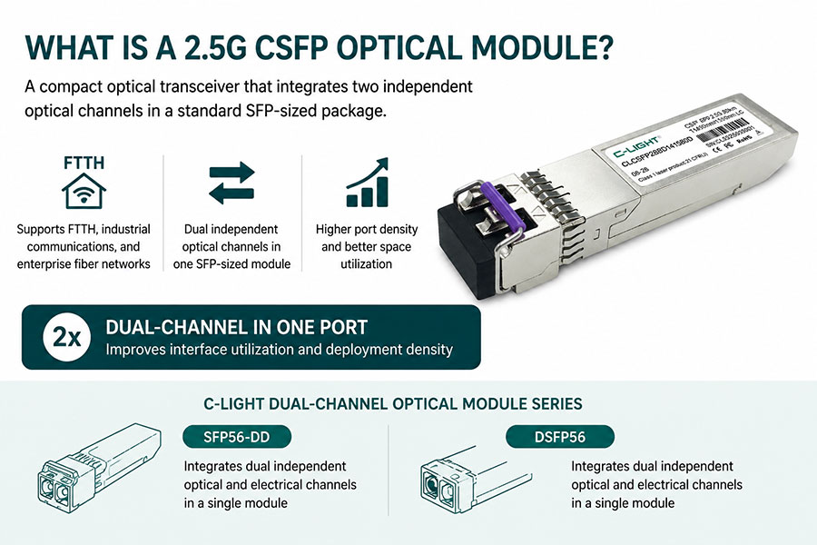
With the rapid growth of FTTH broadband access, industrial communications, and enterprise fiber networks, network designers are increasingly demanding higher port density and better space utilization.
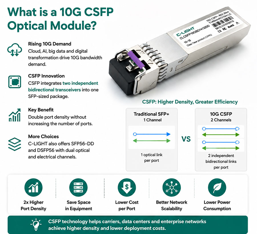
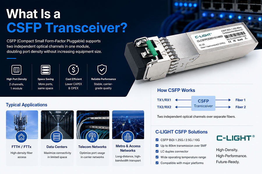
CSFP (Compact Small Form-factor Pluggable) is a compact optical transceiver format that integrates two independent optical channels within a standard SFP-sized package.
Compared with traditional SFP modules, CSFP enables dual-channel communication in a single port, significantly improving interface utilization and deployment density.
Similar to CSFP architecture, C-LIGHT also offers SFP56-DD and DSFP56 product series, which integrate dual independent optical and electrical channels in a single module design.
2. Why Is CSFP Technology Favored by Telecom Operators?
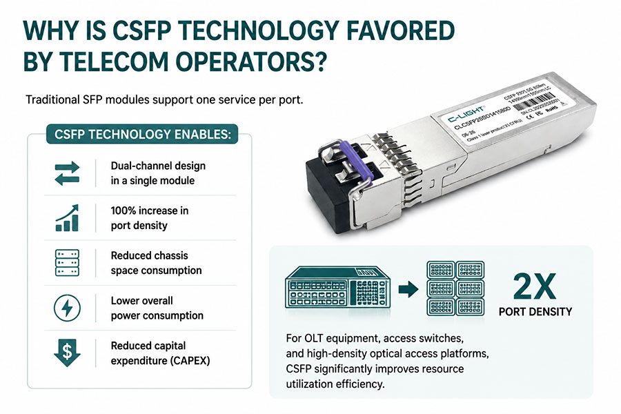
Traditional SFP modules support one service per port.
CSFP technology enables:
Dual-channel design in a single module
100% increase in port density
Reduced chassis space consumption
Lower overall power consumption
Reduced capital expenditure (CAPEX)
For OLT equipment, access switches, and high-density optical access platforms, CSFP significantly improves resource utilization efficiency.
3. C-LIGHT 2.5G CSFP 20km Product Overview
https://www.c-light.com/products/details/1.25G_CSFP.html
The C-LIGHT 2.5G CSFP 20km bidirectional optical module is designed for telecom access networks, industrial optical communications, and enterprise fiber networks.
Key Specifications
| Parameter | Specification |
|---|---|
| Form Factor | CSFP |
| Data Rate | Multi-rate support: 2.5Gbps / 1.25Gbps / 100Mbps |
| Transmitter | 1490nm DFB laser |
| Receiver | 1310nm PIN-TIA |
| Fiber Type | Single-mode fiber (SMF) |
| Transmission Distance | 20km (up to 80km optional) |
| Connector | LC |
| Power Supply | 3.3V |
| Power Consumption | ≤1.5W |
| DDM Monitoring | Supported |
| Operating Temperature | 0~70°C / -40~85°C |
| Hot-Pluggable | Supported |
| DDM Standard | SFF-8472 A0 + B0 |
4. Optical Performance Advantages of 2.5G CSFP 20km
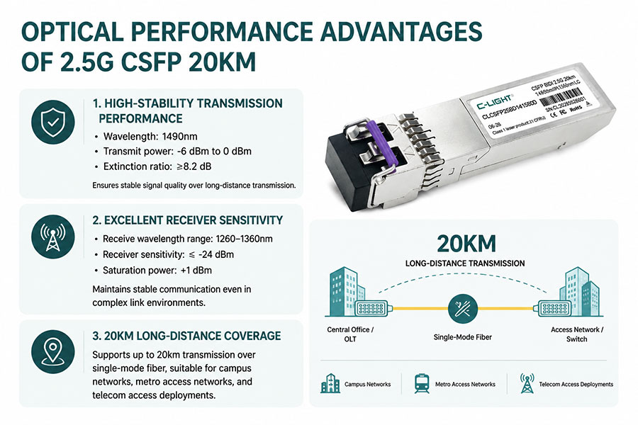
High-Stability Transmission Performance
Wavelength: 1490nm
Transmit power: -6 dBm to 0 dBm
Extinction ratio: ≥8.2 dB
Ensures stable signal quality over long-distance transmission.
Excellent Receiver Sensitivity
Receive wavelength range: 1260–1360nm
Receiver sensitivity: ≤ -24 dBm
Saturation power: +1 dBm
Maintains stable communication even in complex link environments.
20km Long-Distance Coverage
Supports up to 20km transmission over single-mode fiber, suitable for campus networks, metro access networks, and telecom access deployments.
5. Typical Application Scenarios of 2.5G CSFP
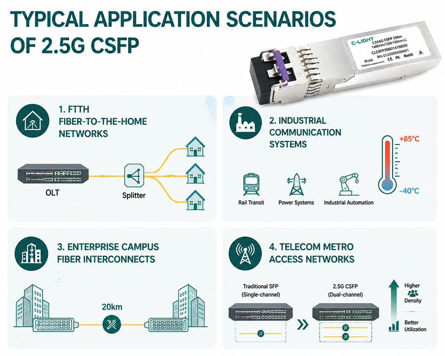
FTTH Fiber-to-the-Home Networks
In GPON, EPON, and metro access networks, CSFP significantly improves OLT port utilization and enables more user connections.
Industrial Communication Systems
Industrial environments require wide-temperature operation. C-LIGHT industrial-grade versions support -40°C to +85°C, making them suitable for rail transit, power systems, and industrial automation.
Enterprise Campus Fiber Interconnects
For building interconnection, data aggregation, and backbone links, 20km transmission distance meets most deployment requirements.
Telecom Metro Access Networks
With dual-channel CSFP design, operators can achieve higher subscriber density within limited chassis space.
6. Why Choose C-LIGHT 2.5G CSFP 20km?
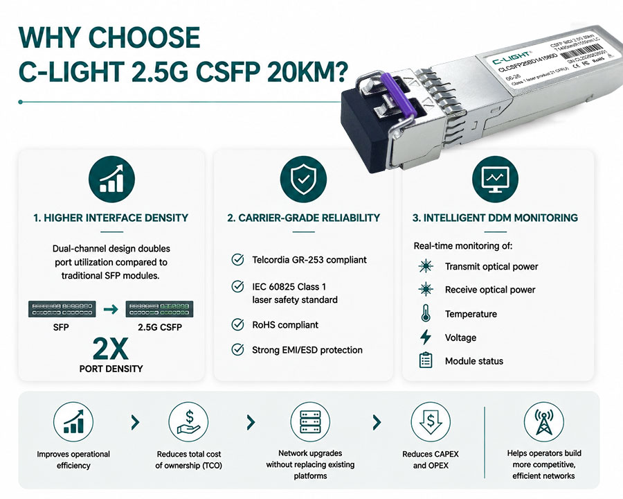
Higher Interface Density
Dual-channel design doubles port utilization compared to traditional SFP modules.
Carrier-Grade Reliability
Telcordia GR-253 compliant
IEC 60825 Class 1 laser safety standard
RoHS compliant
Strong EMI/ESD protection
Intelligent DDM Monitoring
Real-time monitoring of:
Transmit optical power
Receive optical power
Temperature
Voltage
Module status
This improves operational efficiency and reduces total cost of ownership (TCO), allowing network upgrades without replacing existing platforms, helping operators reduce both CAPEX and OPEX.
7. Future Development Trends
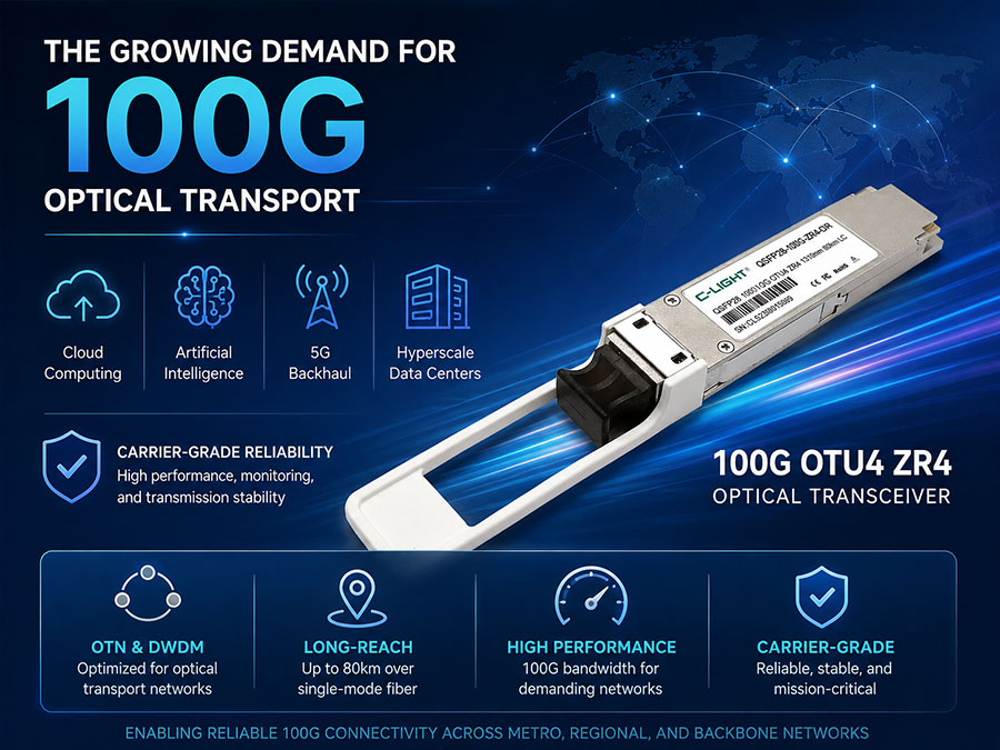
With continuous evolution toward 10G, 25G, and higher-speed optical modules, CSFP technology will remain widely used in FTTH access networks, industrial communication systems, and small-to-medium operator networks.
C-LIGHT will continue to develop 25G and 10G CSFP optical modules.
Due to its high density, low cost, and mature reliability, CSFP technology will remain a key solution in access network deployments for the foreseeable future.
For users seeking higher port density and improved ROI, the C-LIGHT 2.5G CSFP 20km bidirectional optical module remains a highly cost-effective solution.
8. Frequently Asked Questions (FAQ)
Q1: What is the difference between 2.5G CSFP and a standard 2.5G SFP?
A1: The key difference is the number of channels. A standard SFP module has one channel, while a CSFP module integrates two independent transceiver channels within the same SFP-sized package, effectively doubling port density.
| Item | 2.5G CSFP | 2.5G SFP |
|---|---|---|
| Channels | 2 independent channels | 1 channel |
| Size | SFP form factor | SFP form factor |
| Port Utilization | Higher | Standard |
| Density | Double improvement | Normal |
| Application | High-density networks | General networks |
CSFP improves device utilization by enabling dual-channel communication within a single module.
Q2: How should CSFP modules be paired?
A2: CSFP modules must be used in wavelength-paired configurations. For example:
Side A: Tx1310 / Rx1550
Side B: Tx1550 / Rx1310
Common wavelength combinations include 1310nm/1490nm and 1310nm/1550nm.
Q3: What should be considered for short-distance use of a 20km CSFP module?
A3: Optical attenuators are recommended. Long-reach modules may output high optical power, which can overload the receiver in short links, causing errors or potential damage. Attenuation should be calculated based on actual link loss.
Q4: What causes unstable links or failure to establish a connection?
Possible causes include:
Wavelength mismatch between both ends (e.g., 1310nm vs 1550nm)
Incorrect fiber type (must be single-mode fiber)
Optical power out of range (Tx: -5 ~ 0 dBm, Rx sensitivity < -19 dBm)
Dirty fiber connectors causing signal loss
Compatibility issues with switching equipment (MSA compliance required)

 >
>

 >
>
 >
>
 >
>
 >
>
 >
>