TEL:+86 132 6656 7067




1. Why Is It Important to Understand 10G CSFP+ EEPROM Standards?
The 10G CSFP+ optical transceiver is a high-density dual-channel module widely deployed in telecom access networks, enterprise private networks, industrial communications, and SAN storage environments.10G CSFP+丨C-LIGHT
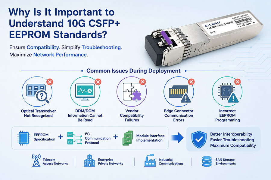
During deployment, network engineers frequently encounter issues such as:
Optical transceiver not recognized
DDM/DOM information cannot be read
Vendor compatibility failures
Edge connector communication errors
Incorrect EEPROM programming
In most cases, these problems are closely related to the EEPROM specification, I²C communication protocol, and module interface implementation.
Understanding these standards helps improve interoperability, simplify troubleshooting, and maximize compatibility across networking platforms.
2. Which Standards Does 10G CSFP+ Follow?

A compliant 10G CSFP+ transceiver follows several industry standards:
CSFP MSA — Defines the mechanical dimensions, dual-channel architecture, and module specifications.
SFF-8431 — Specifies the high-speed electrical interface between the host and the optical module.
SFF-8432 — Defines the mechanical form factor, edge connector, and cage compatibility.
SFF-8472 — Specifies EEPROM memory mapping, Digital Diagnostic Monitoring (DDM/DOM), and the I²C management interface.
I²C Two-Wire Serial Interface — Enables the host system to access EEPROM information and monitor module status.
Most 10G CSFP+ modules support 10Gb/s Ethernet and are compatible with IEEE 802.3ae 10GBASE-SR, 10GBASE-LR, and 10GBASE-ER applications. Designed for dedicated CSFP ports, they provide two independent 10G optical channels, effectively doubling port density in applications such as telecom access and point-to-point fiber links.
Physically, the CSFP+ module uses the same 20-pin, 0.8 mm pitch edge connector and similar mechanical dimensions as a standard SFP+ module while accommodating an additional optical channel. The connector integrates both high-speed differential signals (TX±/RX±) and low-speed management signals (SCL/SDA), following the SFP+ pin assignment.
Overall, a compliant 10G CSFP+ module conforms to CSFP MSA, SFF-8431, and SFF-8432 specifications.
3. What Information Is Stored in the EEPROM?
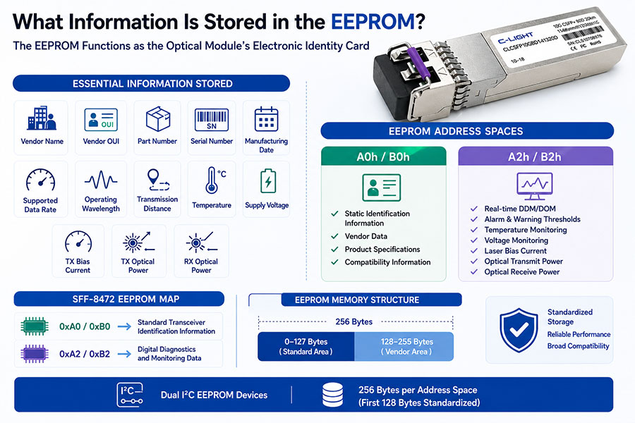
The EEPROM functions as the optical module's electronic identity card.
It stores essential manufacturing and operational information, including:
Vendor Name
Vendor OUI
Part Number
Serial Number
Manufacturing Date
Supported Data Rate
Operating Wavelength
Transmission Distance
Temperature
Supply Voltage
TX Bias Current
TX Optical Power
RX Optical Power
The EEPROM memory is divided into different address spaces:
A0h / B0h
Static identification information
Vendor data
Product specifications
Compatibility information
A2h / B2h
Real-time Digital Diagnostic Monitoring (DDM/DOM)
Alarm and warning thresholds
Temperature monitoring
Voltage monitoring
Laser bias current
Optical transmit power
Optical receive power
According to the SFF-8472 specification, the module contains dual I²C EEPROM memory devices.
0xA0 / 0xB0 stores standard transceiver identification information.
0xA2 / 0xB2 stores digital diagnostics and monitoring data.
Each EEPROM space typically provides 256 bytes, with the first 128 bytes reserved for standardized information defined by the MSA specification.
4. Understanding the CSFP+ Edge Connector Protocol
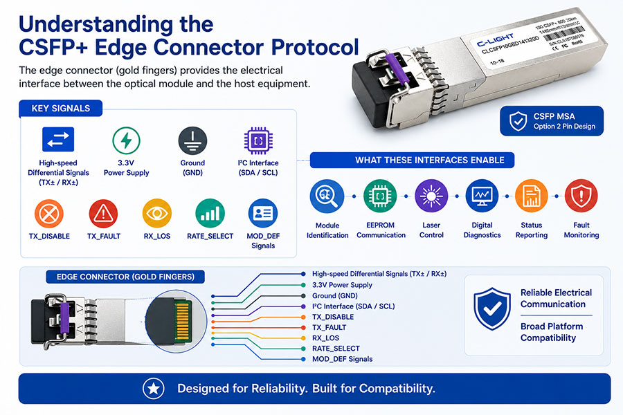
The edge connector (gold fingers) provides the electrical interface between the optical module and the host equipment.
Key signals include:
High-speed differential signals (TX± / RX±)
3.3V Power Supply
Ground (GND)
I²C Interface (SDA / SCL)
TX_DISABLE
TX_FAULT
RX_LOS
RATE_SELECT
MOD_DEF Signals
Together, these interfaces enable:
Module identification
EEPROM communication
Laser control
Digital diagnostics
Status reporting
Fault monitoring
C-LIGHT CSFP+ modules adopt the CSFP MSA Option 2 pin design, ensuring reliable electrical communication and broad platform compatibility.
5. Why Is EEPROM Programming So Important?
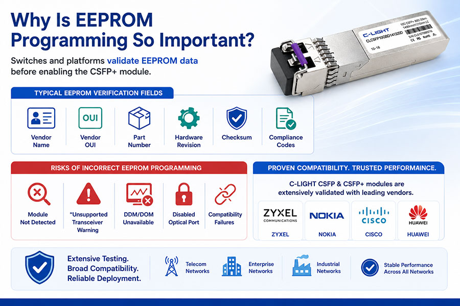
Although most CSFP+ optical modules follow common industry standards, many switches and networking platforms perform additional validation on EEPROM data before enabling the module.
Typical verification fields include:
Vendor Name
Vendor OUI
Part Number
Hardware Revision
Checksum
Compliance Codes
If any of these fields are incorrectly programmed, users may experience:
Module not detected
"Unsupported Transceiver" warning
DDM/DOM unavailable
Disabled optical port
Compatibility failures
The C-LIGHT CSFP and CSFP+ product portfolio has been extensively validated for compatibility with networking equipment from major vendors, including:
ZYXEL
Nokia
Cisco
Huawei
This comprehensive compatibility testing helps ensure stable deployment across telecom, enterprise, and industrial networks.
6. Conclusion
Reliable operation of a 10G CSFP+ optical transceiver depends not only on high-quality optical components but also on strict compliance with CSFP MSA, SFF-8431, SFF-8432, and SFF-8472 standards.
Proper EEPROM programming, standardized digital diagnostics, and comprehensive compatibility validation significantly improve interoperability, simplify deployment, and reduce maintenance costs across modern optical networks.
7. Frequently Asked Questions (FAQ)
Q1. Which EEPROM standard does a 10G CSFP+ module use?
Answer: Most 10G CSFP+ modules follow the SFF-8472 specification, using the A0h/A2h and B0h/B2h memory address spaces together with the I²C two-wire management interface.
Q2. Is the CSFP+ edge connector compatible with SFP+?
Answer: Mechanically, CSFP+ shares a similar form factor and connector design with SFP+, making it compatible with CSFP cages. However, because CSFP+ supports dual-channel operation under the CSFP MSA, its internal functionality and EEPROM management are extended beyond standard SFP+.
Q3. Why can the module be detected but DDM information cannot be read?
Answer: This is typically caused by incomplete SFF-8472 support, host software limitations, firmware restrictions, or incorrect EEPROM programming.
Q4. Can the EEPROM be customized?
Answer: Yes. C-LIGHT provides customized EEPROM programming services, including compatibility coding for major switch vendors as well as OEM and ODM solutions.
Q5. Why do some switches reject third-party optical modules?
Answer: Many networking vendors validate EEPROM fields such as Vendor ID, Vendor OUI, Part Number, and Checksum. If these values do not meet the platform's compatibility requirements, the switch may refuse to activate the module.
Q6. What are the common causes of an "Unsupported Transceiver" message or link failure?
Answer: Compatibility is the most common reason. Some network operating systems only accept vendor-certified optical modules and verify EEPROM information during initialization. Link failures may also result from speed mismatches (such as installing a 1G module in a 10G port), multimode/single-mode fiber mismatches, or unsupported firmware versions. Using validated compatible transceivers, checking system logs, updating switch firmware, or adjusting compatibility settings can help identify and resolve the issue.
 >
>

 >
>
 >
>
 >
>
 >
>
 >
>
 >
>
 >
>