TEL:+86 132 6656 7067




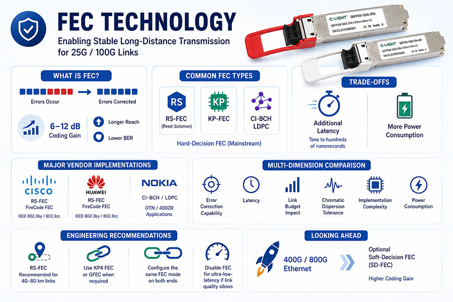
Forward Error Correction (FEC) technology is a key enabler for stable long-distance transmission in 25G and 100G optical links. Major vendors primarily adopt hard-decision FEC schemes, such as Reed-Solomon (RS-FEC), or proprietary FEC technologies including KP-FEC, CI-BCH, and LDPC, to improve link tolerance.
By introducing additional error-correction redundancy, FEC provides a coding gain of typically 6–12 dB, enabling a significantly lower bit error rate (BER) than FEC-disabled operation. This allows optical links to support longer transmission distances or tolerate higher channel loss. However, these benefits come at the cost of additional latency, typically ranging from tens to hundreds of nanoseconds.
Among mainstream networking vendors:
Cisco and Huawei primarily implement IEEE-standard RS-FEC and FireCode FEC, as defined in the IEEE 802.3by and IEEE 802.3cc Ethernet standards for 25G/100G Ethernet.
Nokia adopts more powerful CI-BCH and LDPC FEC schemes in applications such as OTN and 400ZR, where higher transmission performance is required.
This article compares the FEC implementations of major vendors from multiple technical perspectives, including:
FEC type
Error-correction capability
Latency
Impact on link budget
Chromatic dispersion tolerance
Implementation complexity
Power consumption
Representative product examples are also included.
Finally, practical engineering recommendations are provided. For example:
RS-FEC is generally recommended for 40–80 km optical links.
When necessary, select optical transceivers that support KP4 FEC or GFEC.
The FEC mode must be configured identically at both ends of the link.
For ultra-low-latency applications, FEC may be disabled if link quality permits.
Next-generation 400G/800G Ethernet standards can optionally employ soft-decision FEC (SD-FEC) to achieve even higher coding gain.
Common Ethernet FEC Types
| FEC Type | IEEE Standard | Typical Applications |
|---|---|---|
| BASE-R FEC (FC-FEC) | IEEE 802.3 Clause 74 | 25G short-reach links, DAC cables |
| RS-FEC | IEEE 802.3 Clause 91 / 108 | 25G ER, 50G, 100G, 200G, and 400G Ethernet |
| KP4 FEC | IEEE 802.3 Clause 134 | PAM4-based 200G/400G high-speed Ethernet |
1. Why Is FEC More Important for Long-Reach Transmission?
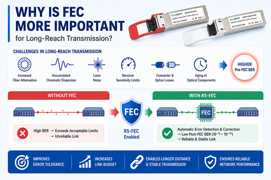
As the transmission distance of an optical link increases from 10 km to 40 km or even 80 km, signal quality is affected by multiple factors, including:
Increased fiber attenuation
Accumulated chromatic dispersion
Laser noise
Receiver sensitivity limitations
Optical connector and splice losses
Aging of optical components
All of these factors contribute to a higher Pre-FEC Bit Error Rate (Pre-FEC BER).
Without FEC, the resulting BER may exceed the acceptable limits required for reliable Ethernet communication. By enabling RS-FEC, the system can automatically detect and correct a large number of random bit errors in real time, reducing the Post-FEC Bit Error Rate (Post-FEC BER) to 10⁻¹² or even 10⁻¹⁵, thereby ensuring stable and reliable link operation.
Therefore, RS-FEC not only improves the system's error tolerance but also significantly increases the available link budget, enabling optical transceivers to achieve their specified transmission distances.
2. Impact of FEC on Link Budget and Receiver Sensitivity
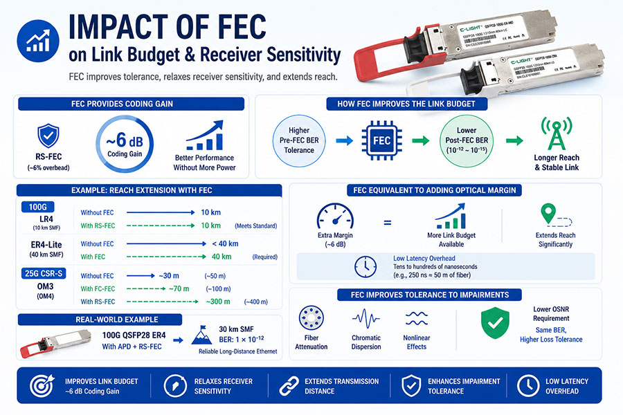
The primary benefit of FEC in improving the link budget is its ability to increase the maximum Pre-FEC Bit Error Rate (Pre-FEC BER) that the system can tolerate. In practical terms, this effectively relaxes the receiver sensitivity requirements, allowing optical links to achieve longer transmission distances.
A typical Reed-Solomon FEC (RS-FEC) implementation with approximately 6% overhead provides a net coding gain of around 6 dB, significantly improving link performance without requiring additional optical power.
For example, a standard 100G LR4 optical transceiver from Cisco supports transmission over 10 km of single-mode fiber without FEC, with a receiver sensitivity of approximately –10.7 dBm. Enabling RS-FEC does not increase its specified transmission distance because the module is already designed to meet the 10 km Ethernet standard. However, when the same 10 km architecture is implemented using single-wavelength LR1 or enhanced ER1/ER4-Lite technologies, host-side FEC becomes necessary to achieve the full specified transmission distance. For instance, ER4-Lite requires FEC support for reliable operation over 40 km.
The benefits of FEC are even more evident in short-reach applications. At 25G, Cisco CSR-S optical modules support only approximately 30 m on OM3 fiber (or 50 m on OM4) when FEC is disabled. Enabling IEEE FC-FEC extends the reach to approximately 70 m on OM3 (or 100 m on OM4), while enabling RS-FEC further increases the supported distance to approximately 300 m on OM3 (or 400 m on OM4), demonstrating a substantial improvement in the available link budget.
Overall, the coding gain provided by FEC is equivalent to adding a significant amount of optical margin to the transmission link. Although the additional processing latency is typically only tens to hundreds of nanoseconds (for example, 250 ns corresponds to the propagation delay of roughly 50 meters of optical fiber), the resulting coding gain can compensate for several decibels of optical loss, effectively extending transmission reach far beyond what additional fiber length alone would imply.
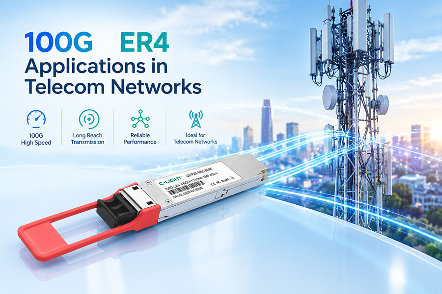
In addition, FEC improves system tolerance to various physical impairments, including fiber attenuation, chromatic dispersion, and optical nonlinearities. At the same target BER, it allows the link to tolerate higher channel loss or operate with a lower required Optical Signal-to-Noise Ratio (OSNR). For example, 100G QSFP28 ER4 100G QSFP28 SR4/LR4/ER4/ZR4 Optical Transceiver丨C-LIGHT optical transceivers that combine APD receivers with RS-FEC can achieve a BER of 1 × 10⁻¹² over 30 km single-mode fiber, providing reliable long-distance Ethernet transmission.
3. Latency and Implementation Complexity
The latency introduced by FEC primarily consists of the time required for the encoder to generate redundancy bits and for the decoder to detect and correct transmission errors. In practical implementations, hard-decision FEC (HD-FEC) typically introduces an on-chip decoding latency ranging from tens to hundreds of nanoseconds.
For example:
25G RS-FEC: approximately 250 ns (equivalent to the propagation delay of about 50 meters of optical fiber)
FC-FEC (FireCode FEC): approximately 82 ns
From an implementation perspective, hard-decision FEC requires relatively moderate hardware resources. It can be efficiently implemented using ASICs or FPGAs, offering low power consumption and compact silicon area. In contrast, soft-decision FEC (SD-FEC) based on LDPC algorithms requires a large number of multiply-accumulate (MAC) operations, resulting in significantly higher power consumption, greater silicon area, and increased implementation complexity.
Overall, hard-decision FEC relies mainly on finite-field arithmetic, making it considerably simpler and more power-efficient than soft-decision decoding. As a result, modern commercial Ethernet switch ASICs commonly integrate dedicated RS-FEC and KP-FEC hardware engines, while high-speed 400G and 800G coherent DSPs typically incorporate SD-FEC/LDPC decoders to achieve higher coding gains.
4. Standards and Interoperability
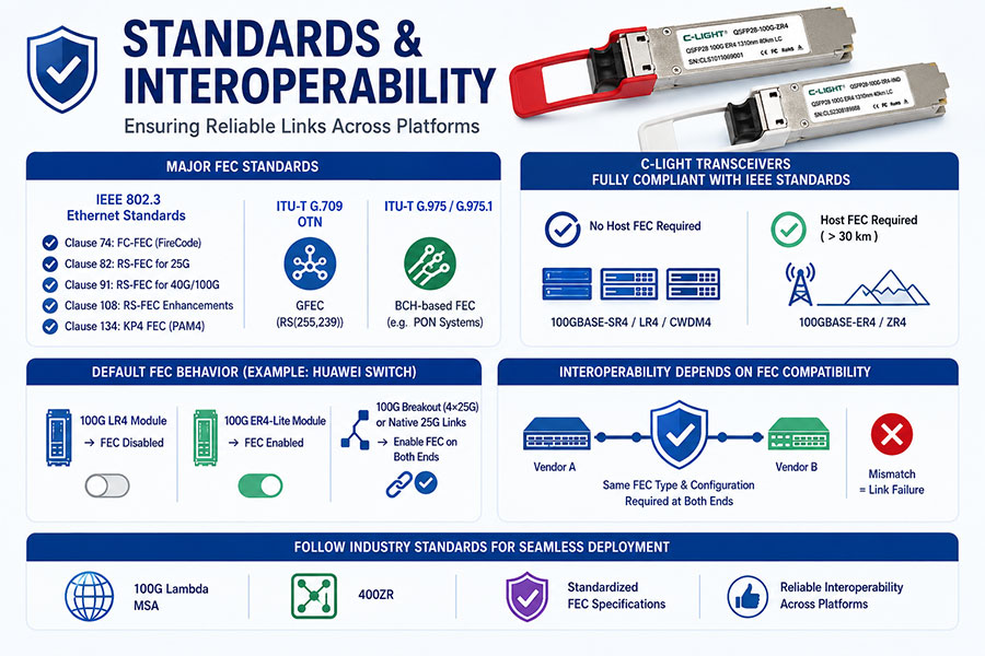
The major FEC standards used in Ethernet and optical transport networks include:
IEEE 802.3 Ethernet Standards
Clause 74: FC-FEC (FireCode FEC)
Clause 91: RS-FEC for 40G/100G Ethernet
Clause 82: RS-FEC for 25G Ethernet
Clause 108: RS-FEC enhancements
Clause 134: KP4 FEC for PAM4-based Ethernet
ITU-T G.709 Optical Transport Network (OTN), which specifies GFEC based on RS(255,239).
ITU-T G.975/G.975.1, which defines BCH-based FEC schemes used in various optical transmission systems, including PON applications.
C-LIGHT optical transceivers are generally designed in full compliance with IEEE Ethernet standards. For example:
100GBASE-SR4, 100GBASE-LR4, and 100GBASE-CWDM4 typically operate without requiring host-side FEC.
100GBASE-ER4 and 100GBASE-ZR4, when deployed over transmission distances exceeding 30 km, generally require host-side FEC to ensure reliable link performance.
Huawei switch documentation also indicates that the default FEC configuration depends on the installed optical module. For example:
When a 100G LR4 module is inserted, FEC is disabled by default.
When a 100G ER4-Lite module is installed, FEC is enabled by default.
For 100G breakout (4 × 25G) or native 25G Ethernet links, Huawei recommends enabling FEC on both ends of the connection.
Interoperability between different vendors also depends on FEC compatibility. The FEC type and configuration must match at both ends of the link; otherwise, link establishment may fail. For example, interoperability between Aruba and Cisco at 25G Ethernet requires both devices to enable IEEE RS(544,514) FEC. Using incompatible FEC modes can prevent the link from coming up.
In multi-vendor network deployments, following widely adopted industry standards—such as the 100G Lambda MSA, 400ZR, and other standardized FEC specifications—is recommended to ensure reliable interoperability and seamless deployment across different networking platforms.
5. FEC Configuration Examples from Major Network Equipment Vendors
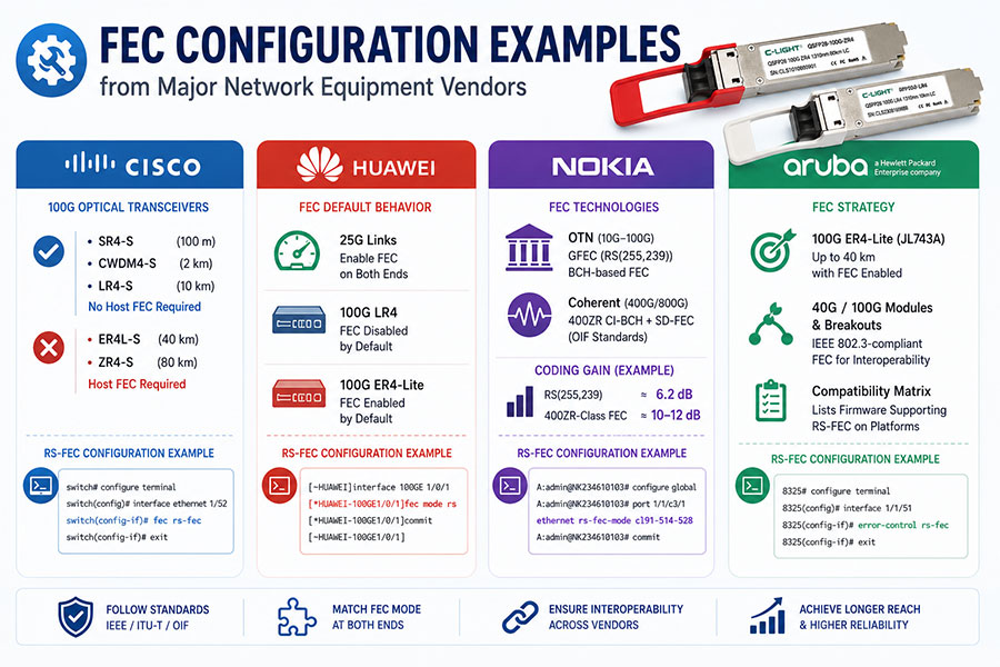
Different network equipment vendors implement FEC according to IEEE standards and specific application requirements. The following examples illustrate the typical FEC configurations used by leading vendors.
Cisco
Among Cisco's 100G optical transceivers:
QSFP-100G-SR4-S (100 m over MMF)
QSFP-100G-CWDM4-S (2 km)
QSFP-100G-LR4-S (10 km)
typically do not require host-side FEC under standard operating conditions.
In contrast:
QSFP-100G-ER4L-S (40 km)
QSFP-100G-ZR4-S (80 km)
require host-side FEC to achieve their full specified transmission distances.
Cisco RS-FEC Configuration Example
switch# configure terminal
Enter configuration commands, one per line. End with CNTL/Z.
switch(config)# interface ethernet 1/52
switch(config-if)# fec rs-fec
switch(config-if)# exit
Huawei
Huawei primarily adopts IEEE-standard RS-FEC and BASE-R FEC for 25G and 100G Ethernet links.
According to Huawei configuration documentation:
25G Ethernet links should enable FEC on both ends of the connection to reduce packet errors.
100G LR4 optical modules have FEC disabled by default.
100G ER4-Lite optical modules have FEC enabled by default.
Huawei RS-FEC Configuration Example
[~HUAWEI]interface 100GE 1/0/1
[*HUAWEI-100GE1/0/1]fec mode rs
[*HUAWEI-100GE1/0/1]commit
[~HUAWEI-100GE1/0/1]
Nokia (Alcatel-Lucent)
In traditional 10G–100G OTN networks, Nokia widely adopts ITU-T GFEC (RS(255,239)) and BCH-based FEC schemes.
For coherent optical transmission, Nokia's 400G and 800G coherent modules implement either proprietary FEC algorithms or industry-standard schemes defined by the OIF, such as 400ZR CI-BCH + SD-FEC.
Nokia's technical publications focus primarily on theoretical analysis. In its article "What the FEC?", the company summarizes the performance of different FEC technologies:
RS(255,239): approximately 6.2 dB coding gain
Modern 400ZR-class FEC: approximately 10–12 dB coding gain
Nokia routing and switching documentation also indicates that certain 25G and 100G Ethernet interfaces support RS-FEC, KP1-FEC, and related modes, although detailed model-specific information is relatively limited.
As an example, Nokia PSE/Ciena-compatible QSFP28 100G LR4 optical transceivers comply with IEEE Ethernet standards and require RS-FEC when appropriate. At present, Nokia has not publicly released detailed performance test data for these modules.
Nokia RS-FEC Configuration Example
A:admin@NK234610103# configure global
A:admin@NK234610103# port 1/1/c3/1 ethernet rs-fec-mode cl91-514-528
*[gl:/configure]
A:admin@NK234610103# commit
Aruba (HPE)
Aruba (HPE) switches follow an FEC strategy similar to Cisco's.
For example, the 100G ER4-Lite (JL743A) optical transceiver is specified for transmission distances of up to 40 km, which is generally achieved with FEC enabled.
Aruba also offers a wide range of 40G and 100G optical modules, including breakout transceivers, that interoperate using IEEE 802.3-compliant FEC mechanisms. The official Aruba compatibility matrix identifies the firmware versions that support RS-FEC on specific switch platforms.
Aruba RS-FEC Configuration Example
8325# configure terminal
8325(config)# interface 1/1/51
8325(config-if)# error-control rs-fec
8325(config-if)# exit
6. Engineering Deployment Recommendations (Priority Order)
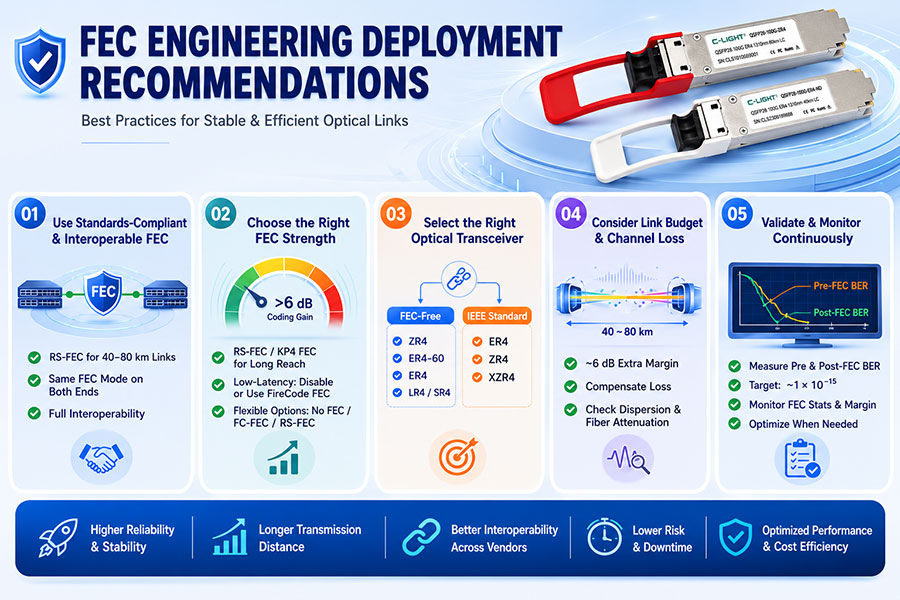
6.1 Use Standards-Compliant and Interoperable FEC Modes
For 40–80 km optical links, it is generally recommended to deploy transceivers that support RS-FEC. For example, Cisco and Huawei 100G ER4-Lite, ER4, and ZR4 solutions typically require host-side FEC to achieve their full specified transmission distances. The switches or network devices at both ends of the link must be configured with the same FEC mode to ensure successful link establishment and stable operation.
For customers with different deployment requirements, C-LIGHT also provides FEC-independent optical transceivers, including CL100GQSFPSZR4, CL100GQSFPSER4-60, and CL100GQSFPSER4, which are specifically designed to support 40–80 km applications without relying on host-side FEC.100G QSFP28 SR4/LR4/ER4/ZR4 Optical Transceiver丨C-LIGHT
6.2 Select the Appropriate FEC Strength Based on Application Requirements
The choice of FEC should be based on transmission distance, link quality, and latency requirements.
For long-distance links or fiber infrastructure with relatively high loss, RS-FEC or KP4 FEC is recommended to provide a coding gain of more than 6 dB, thereby improving overall link robustness.
For ultra-low-latency applications, such as high-frequency trading (HFT), FEC may be disabled or replaced with low-latency FireCode FEC, provided that the link quality satisfies the required BER specifications.
For example, C-LIGHT 100G SR4 and LR4 optical transceivers support flexible deployment under multiple FEC configurations, including No FEC, FC-FEC, and RS-FEC, allowing customers to optimize the balance between latency and transmission reliability.
6.3 Select Optical Transceivers According to Application Requirements and Industry Standards
To address different customer deployment scenarios, C-LIGHT offers both FEC-independent and standard IEEE-compliant optical transceiver solutions.
FEC-independent products include:
CL100GQSFPSZR4
CL100GQSFPSER4-60
CL100GQSFPSER4
For conventional IEEE-standard products, including:
host-side FEC should be enabled to ensure stable long-distance link operation in accordance with Ethernet specifications.
6.4 Consider Link Budget and Physical Channel Loss
When designing an optical link, the additional link budget provided by FEC should be fully considered.
As a general guideline, approximately 6 dB of coding gain can effectively compensate for several decibels of channel loss, enabling significantly longer transmission distances or providing additional optical margin. In practical deployments, this additional margin can be used to support transmission distances beyond 40 km while maintaining reliable performance.
Other physical-layer factors—including chromatic dispersion, fiber attenuation, and the potential need for optical amplifiers or repeaters—should also be evaluated during network planning. For multimode fiber applications, appropriate short-reach operating modes, such as CSR, should be selected where applicable.
6.5 Perform Validation and Continuous Monitoring
After deployment, comprehensive link validation should be performed by measuring both Pre-FEC BER and Post-FEC BER.
The Pre-FEC BER should remain within the correction capability of the selected FEC scheme, while the Post-FEC BER should meet the target performance level, typically around 1 × 10⁻¹⁵.
Using professional test equipment to monitor error distribution, FEC correction statistics, and available correction margin can help verify link quality. If necessary, transmission performance can be further optimized by adjusting transmitter output power, adding optical attenuators, or fine-tuning other optical parameters.
7. Conclusion
Forward Error Correction (FEC) has become an essential technology for modern long-reach Ethernet networks.
According to Cisco's official documentation, enabling RS-FEC allows 25G ER and 100G ER4-Lite optical transceivers to achieve their full specified transmission distances, while disabling FEC may significantly reduce the maximum supported reach. At the same time, major networking vendors—including Huawei, Nokia, and Aruba—provide comprehensive FEC configuration mechanisms to improve long-distance transmission reliability and ensure interoperability across multi-vendor network environments.
As optical networking continues to evolve toward higher speeds and longer transmission distances, RS-FEC is no longer simply an optional feature. It has become a fundamental technology for ensuring the stable operation of 25G and 100G long-reach optical links, and it also serves as a critical foundation for the continued evolution of 400G, 800G, and future 1.6T optical networks.
8. Frequently Asked Questions (FAQ)
Q1. What is the primary purpose of FEC?
Answer: Forward Error Correction (FEC) automatically detects and corrects transmission errors without requiring data retransmission. This improves link reliability, reduces the bit error rate (BER), and enables longer transmission distances.
Q2. Do all 25G optical transceivers require RS-FEC?
Answer: No. Not all 25G optical transceivers require RS-FEC. Short-reach modules, such as 25G SR, typically operate without RS-FEC. However, long-reach modules, such as 25G ER (40 km), generally require RS-FEC to achieve their full specified transmission performance and ensure reliable link operation.
Q3. Why does enabling FEC increase the transmission distance?
Answer: FEC corrects random bit errors caused by factors such as fiber attenuation, chromatic dispersion, and optical noise. As signal quality degrades over longer distances, FEC enables the receiver to recover data accurately, effectively increasing the available link budget and extending the maximum transmission reach.
Q4. What happens if interconnected devices from different vendors use different FEC configurations?
Answer: Mismatched FEC configurations may prevent the link from being established, cause intermittent link failures, or result in excessive bit errors. Therefore, when interconnecting equipment from vendors such as Cisco, Huawei, Nokia, and Aruba, both ends of the link should be configured with the same FEC mode to ensure compatibility and stable operation.
Q5. Will RS-FEC continue to play an important role in future high-speed Ethernet networks?
Answer: Yes. RS-FEC has become a standard technology for 25G, 100G, 200G, 400G, and 800G Ethernet. As Ethernet continues to evolve toward 1.6T and even higher data rates, RS-FEC—and more advanced FEC technologies—will remain fundamental to providing reliable error correction, improving transmission quality, and ensuring stable high-speed optical communication.
 >
>

 >
>
 >
>
 >
>
 >
>
 >
>
 >
>
 >
>