TEL:+86 132 6656 7067




1. Introduction
AI data centers are moving toward higher network bandwidth as GPU clusters, distributed training, inference, storage, and east-west traffic continue to scale. After the transition from 400G to 800G, 1.6T optical transceivers are emerging as the next generation of high-speed optical connectivity. A 1.6T optical transceiver can provide up to 1.6Tbps of aggregate bandwidth through a single optical port, helping increase network capacity and reduce the number of physical connections required by large AI fabrics.
2. What Is a 1.6T Optical Transceiver?
A 1.6T optical transceiver is a high-speed pluggable optical module designed to provide up to 1.6Tbps of aggregate data transmission. It converts electrical signals from a switch, NIC, router, or other network device into optical signals for fiber transmission and converts received optical signals back into electrical signals at the remote end.
3. Why AI Data Centers Need 1.6T Optical Transceivers
AI workloads generate substantial communication traffic between GPUs, network adapters, switches, storage systems, and compute nodes. Distributed training also requires frequent synchronization of gradients, parameters, activations, and datasets. Higher bandwidth per port can help scale these networks while controlling port count and physical interconnection complexity.
4. From 400G to 800G to 1.6T
High-speed AI networking is progressing through successive bandwidth generations. 400G provides the foundation for high-speed data center fabrics, 800G increases bandwidth density, and 1.6T doubles the aggregate bandwidth of 800G. Each generation also introduces new challenges in lane rate, optical components, electrical signal integrity, thermal management, packaging, and manufacturing.
5. 1.6T Bandwidth Advantage
A 1.6T port provides twice the aggregate bandwidth of an 800G port. This allows network designers to increase capacity without simply doubling the number of optical ports. The resulting architecture can provide higher bandwidth density in large AI switches and high-performance computing systems.
6. Common 1.6T Architecture
A common 1.6T optical architecture uses eight 200G-class electrical lanes and eight 200G-class optical lanes. PAM4 signaling is typically used to achieve the required per-lane data rate. The exact architecture depends on the optical technology, host interface, transmission distance, and product implementation.
7. Eight 200G Lanes
Eight 200G-class lanes provide an aggregate 1.6Tbps capacity. This multi-lane approach allows module designers to distribute the total bandwidth across multiple optical channels rather than relying on one extremely high-speed channel.
8. PAM4 Signaling
PAM4 uses four signal amplitude levels and carries two bits per symbol. It enables higher data rates per electrical and optical lane compared with traditional NRZ signaling. At 1.6T, PAM4 signal integrity becomes increasingly important because the smaller eye openings make the link more sensitive to loss, noise, crosstalk, and distortion.
9. 200G Per-Lane Technology
200G-class optical lanes are an important building block for 1.6T networking. Research and commercial demonstrations have shown 200G-per-lane PAM4 technologies in both multimode and single-mode architectures. These technologies support the move toward eight-lane 1.6T optical modules.
10. Electrical Interface
The electrical side of a 1.6T transceiver connects to the switch ASIC, NIC, or other host device. A common architecture uses eight 200G-class electrical lanes. The actual electrical implementation can vary depending on the host SerDes generation and module architecture.
11. Optical Interface
The optical interface converts high-speed electrical lanes into optical channels and launches them into the fiber infrastructure. 1.6T modules can use parallel optics or wavelength-division multiplexing depending on the required reach and optical design.
12. OSFP Form Factor
OSFP is an important form factor for high-speed 800G and 1.6T networking. The larger mechanical envelope provides room for thermal management and high-speed optical or electrical components. Next-generation 1.6T products can use OSFP-based architectures, including reduced-height designs for specific system requirements.
13. OSFP-RHS
OSFP-RHS refers to a reduced-height OSFP architecture designed for high-density networking environments. It can provide a lower mechanical height while retaining the high-bandwidth capability required for 1.6T applications. This type of design can be relevant to switches where optical-port density and mechanical integration are important.
14. OSFP-XD
OSFP-XD is another high-density form-factor direction for next-generation networking. Depending on the platform and generation, high-speed interfaces can use higher lane counts and advanced electrical architectures. The specific host and connector requirements must always be verified before deployment.
15. Silicon Photonics
Silicon photonics is one of the important technologies being developed for 1.6T transceivers. A silicon photonic integrated circuit can combine waveguides, modulators, multiplexers, splitters, and photodetectors into a compact optical engine, providing high optical integration and multi-channel scalability.
16. EML Technology
EML remains relevant to high-speed single-mode optical modules. By combining a laser source and electro-absorption modulator in one device, EML can provide high-speed optical performance for selected reach and wavelength architectures. At 1.6T, 200G-class EML technology is one of the optical approaches being developed for higher-speed transceivers.
17. VCSEL Technology
VCSEL technology is widely used in short-reach multimode optical networking. Advanced 200G-class VCSELs are being developed for 1.6T short-reach transceivers, making VCSEL-based architectures relevant to future AI cluster connectivity where low cost and short-distance performance are important.
18. Single-Mode 1.6T Optics
Single-mode 1.6T optical modules are designed for longer transmission distances than multimode solutions. They can use optical technologies such as silicon photonics, EML, or other laser architectures depending on the product and target reach.
19. Multimode 1.6T Optics
Multimode 1.6T solutions target shorter high-density links inside AI data centers. VCSEL-based optical engines can provide a practical path for short-reach connectivity where the distance is limited and cost, power, and optical density are important.
20. 1.6T SR8
SR8 is a short-reach parallel optical architecture using eight optical lanes. An emerging 1.6T SR8 design can use eight 200G-class optical lanes, making it suitable for short multimode fiber connections in high-density data centers.
21. 1.6T DR8
DR8 is a parallel single-mode architecture based on eight optical channels. It is intended for higher-reach data center connectivity compared with short-reach multimode designs. Different 1.6T DR8 implementations may support different distances and optical technologies.
22. 1.6T 2DR4
2DR4 combines two DR4 optical groups to provide an aggregate 1.6T interface. This architecture can use four optical channels per group and is relevant to 500m-class single-mode data center connections in certain implementations.
23. 1.6T 2×FR4
2×FR4 uses two FR4 optical groups with wavelength-multiplexed channels. This architecture can provide extended reach compared with short parallel optics and can be used for links around the 2km class in some product implementations.
24. Reach Options
1.6T optical transceivers are not limited to one transmission distance. Short-reach multimode solutions, medium-reach single-mode solutions, and longer-reach wavelength-multiplexed solutions can all serve different parts of an AI data center network.
25. 100m-Class Short Reach
Short-reach 1.6T modules can target connections within racks, across adjacent racks, or between closely positioned switching systems. Multimode fiber and VCSEL-based architectures are particularly relevant to this segment.
26. 500m-Class Connectivity
500m-class single-mode connectivity can address larger areas of a data center where 100m multimode links are insufficient. 1.6T 2DR4 architectures are one example of a high-speed solution targeting this type of deployment.
27. 2km-Class Connectivity
2km-class 1.6T links can support longer connections within large facilities and selected data center interconnect scenarios. WDM-based architectures such as 2×FR4 can provide the required optical reach while retaining a high-bandwidth pluggable form factor.
28. AI Training Clusters
AI training systems distribute workloads across many GPUs. Communication between compute nodes can include all-reduce, all-to-all, parameter synchronization, and gradient exchange. High-bandwidth optical links can help prevent network capacity from becoming a bottleneck in these communication-intensive workloads.
29. AI Inference Networks
Inference systems also generate substantial traffic when large models are distributed across multiple servers or accelerators. High-bandwidth connectivity can support model serving, data movement, synchronization, and storage access in large inference clusters.
30. GPU-to-Switch Connectivity
GPU servers communicate with the network fabric through high-speed NICs and switches. Depending on the platform, 1.6T optical transceivers can be used to provide very high-bandwidth links between network adapters and switching systems.
31. Switch-to-Switch Connectivity
Large AI fabrics require high-capacity links between leaf, spine, and aggregation switches. 1.6T optical transceivers can increase bandwidth per switch port and support the scaling of high-performance leaf-spine architectures.
32. Leaf-Spine Networks
Leaf-spine architectures create predictable paths between compute nodes and network layers. As the number of GPUs grows, the amount of east-west traffic between leaf and spine switches increases. Higher-capacity optical links can help scale these network layers without a proportional increase in physical port count.
33. Scale-Up Connectivity
Scale-up architectures focus on communication among closely connected accelerators and compute resources. Optical interconnects can complement electrical interconnects where the physical distance and bandwidth requirements justify optical transmission.
34. Scale-Out Connectivity
Scale-out expands the number of compute nodes in a cluster. 1.6T optical links can provide higher-capacity connections between large groups of GPU servers, switches, and network fabrics.
35. Scale-Across Connectivity
As AI infrastructure expands across multiple facilities or network domains, longer optical links and DCI technologies become increasingly important. 1.6T connectivity can form part of future high-capacity links where the required optical architecture supports the distance.
36. AI Network Bandwidth
Higher bandwidth per port can reduce the number of ports required to carry the same aggregate traffic. This can simplify switch architectures and increase bandwidth density, although total network capacity still depends on switch ASIC performance, topology, oversubscription, and application traffic patterns.
37. Port Density
Port density is a major concern in AI switches. Increasing the capacity of each optical port allows network designers to deliver more aggregate bandwidth within a limited front-panel space. The tradeoff is that higher-speed ports also increase electrical, optical, and thermal design requirements.
38. Power Consumption
1.6T optical transceivers generally require more advanced optical and electrical components than earlier generations. Power consumption depends on the DSP, laser, modulator, driver, receiver, FEC, control electronics, and cooling architecture. Therefore, the 1.6T data-rate label alone does not determine module power.
39. DSP Power
DSPs can be one of the largest power contributors in high-speed optical modules. Advanced semiconductor nodes can improve processing efficiency, while architectural approaches such as LPO can reduce some module-level signal processing. The final power level depends on the complete implementation.
40. FEC Processing
Forward error correction can improve link robustness by correcting certain transmission errors. In conventional high-speed transceivers, FEC-related processing can contribute to module power and latency. The exact FEC location and architecture depend on the host and transceiver implementation.
41. LPO for 1.6T
Linear-drive Pluggable Optics is another architecture being explored for high-speed connectivity. LPO reduces or bypasses some module-level DSP functions and relies more heavily on the host SerDes and linear optical components. At 1.6T, LPO can potentially reduce module power, but it also introduces tighter electrical channel and interoperability requirements.
42. LRO and Retimed Optics
Not all low-power architectures completely remove signal-processing functions. Linear receive or retimed approaches can retain selected signal-conditioning functions. The resulting power, latency, and signal-integrity characteristics depend on the exact architecture.
43. Thermal Management
Thermal management is one of the most important challenges for 1.6T optical transceivers. Higher bandwidth increases the power density of optical and electrical components, requiring effective heat spreading, heat sinking, airflow, or advanced liquid-based cooling in some high-density systems.
44. Heat Sink Design
Heat sinks transfer heat from high-power components toward the cooling environment. In 1.6T OSFP architectures, mechanical design must balance heat dissipation with connector dimensions, airflow, port density, and neighboring module clearance.
45. Reduced-Height Thermal Design
Reduced-height optical modules can improve system-level mechanical compatibility in certain switches. However, lowering the available mechanical height can make thermal design more challenging, requiring efficient heat spreading and optimized airflow.
46. Air Cooling
Air cooling remains suitable for many optical systems. Its effectiveness depends on module power, heat-sink design, airflow rate, inlet temperature, switch layout, and rack density. Lower-power 1.6T architectures may help extend the practical range of air-cooled deployments.
47. Liquid Cooling
Liquid cooling can provide stronger heat-transfer capability for high-density AI systems. Direct-to-chip, cold-plate, and immersion architectures are different approaches. A standard air-designed optical module should not automatically be assumed to be suitable for immersion operation.
48. Optical Module Materials
High-speed modules use many materials, including PCBs, optical interfaces, polymers, adhesives, metals, and thermal components. Material selection affects thermal performance, reliability, mechanical stability, and compatibility with the selected cooling environment.
49. Signal Integrity
At 200G per lane, electrical signal integrity becomes a critical design factor. Insertion loss, return loss, crosstalk, reflections, connector performance, PCB routing, package design, and equalization all influence the final link margin.
50. Host SerDes
The host SerDes generates and receives the high-speed electrical lanes connected to the optical module. Its signal quality and equalization capability directly influence optical-module performance, especially in architectures that reduce module-level DSP.
51. Electrical Channel Loss
The complete electrical path includes the switch ASIC, package, PCB traces, connector, module electrical interface, and optical engine. As lane speeds increase, accumulated loss and distortion become increasingly difficult to manage.
52. Optical Link Budget
For single-mode 1.6T links, optical link budget is determined by transmitter power, receiver sensitivity, fiber attenuation, connector loss, splice loss, and other passive components. The selected module and fiber system must provide sufficient margin for the intended distance.
53. Fiber Infrastructure
1.6T deployments can use different fiber infrastructures depending on reach. Multimode systems may use OM4 or other suitable grades for short-reach applications, while single-mode systems use fiber designed for longer-distance optical transmission.
54. MPO Connectivity
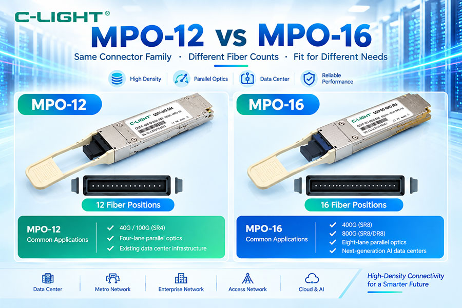
Parallel optical 1.6T architectures can use high-density multi-fiber connectors such as MPO-based interfaces. Connector type, fiber count, lane mapping, and polarity must match the selected optical architecture.
55. LC Connectivity
WDM-based 1.6T architectures can use duplex LC or related interfaces depending on the module design. This can simplify connection to single-mode fiber infrastructure where separate fibers carry multiplexed optical channels.
56. Connector Polarity
Polarity is critical for parallel optical systems. Transmit and receive fibers must be mapped correctly between both endpoints. Incorrect polarity can prevent the link from establishing even when the modules and cables are otherwise compatible.
57. Optical Lane Mapping
Lane mapping determines how electrical and optical lanes correspond to each other. In 1.6T parallel architectures, incorrect lane mapping can result in partial link failure, high error rates, or complete link loss.
58. Management and CMIS
Modern pluggable optical modules can use standardized management interfaces such as CMIS. Management functions may include module identification, temperature, voltage, optical power, laser bias, alarms, and other diagnostic information.
59. DOM and DDM
Digital monitoring functions can help operators identify optical and thermal problems. Depending on the module implementation, monitoring data may include transmit power, receive power, temperature, voltage, bias current, and module alarms.
60. Host Compatibility
A 1.6T optical transceiver must be compatible with the host switch, NIC, router, or other platform. Mechanical fit, electrical interface, lane rate, power class, management, firmware, coding, FEC, and optical specifications all need to be checked.
61. Vendor Coding
Host devices can read module identification information before enabling a port. Vendor coding and EEPROM data may therefore influence whether a 1.6T transceiver is accepted by a specific platform.
62. Interoperability
Interoperability becomes more challenging as lane speeds increase. Optical modules, switches, NICs, cables, fiber systems, and software should be tested as a complete link. Multi-vendor interoperability cannot be assumed solely from the same nominal data rate.
63. Reliability
High-speed optical modules must operate within defined electrical, optical, thermal, and mechanical limits. Reliability testing should evaluate temperature cycling, optical performance, electrical performance, connector behavior, laser stability, and long-duration operation.
64. Manufacturing Challenges
1.6T optical modules require tighter manufacturing tolerances than earlier generations. Optical coupling, high-speed electrical assembly, alignment, packaging, thermal interfaces, and testing all become more demanding as the number and speed of lanes increase.
65. Optical Testing
Testing can include optical output power, receiver sensitivity, extinction ratio, eye quality, TDECQ, BER, wavelength, and other parameters appropriate to the optical architecture. High-speed PAM4 links require careful characterization of both transmitter and receiver performance.
66. BER Testing
Bit error rate is a fundamental metric for evaluating link quality. BER testing can identify problems caused by weak optical power, electrical signal degradation, poor fiber connections, lane mapping errors, or insufficient system margin.
67. FEC Monitoring
FEC counters can provide useful information about link health. Increasing corrected-error counts may indicate deteriorating signal quality even when the link remains operational. Uncorrectable errors can indicate a more serious physical or configuration problem.
68. Power per Bit
Power per bit is an important metric when comparing different generations of optical technology. A 1.6T module may consume more absolute power than an 800G module while still delivering lower power per transmitted bit when the architecture is sufficiently efficient.
69. 1.6T vs 800G
| Parameter | 800G Optical Transceiver | 1.6T Optical Transceiver |
|---|---|---|
| Aggregate Data Rate | 800Gbps | 1.6Tbps |
| Common Lane Approach | 8 × 100G or 4 × 200G | 8 × 200G |
| Modulation | PAM4 | PAM4 |
| Bandwidth per Port | 800G | 1.6T |
| Thermal Challenge | High | Very High |
| AI Application | Large-scale AI networks | Next-generation AI networks |
70. 1.6T vs 400G
Compared with 400G, a single 1.6T port provides four times the aggregate bandwidth. This can significantly increase bandwidth density in large switching platforms. However, 1.6T also requires more advanced electrical interfaces, optical engines, thermal management, and testing.
71. 1.6T Optical Module vs 1.6T DAC
| Feature | 1.6T Optical Transceiver | 1.6T DAC |
|---|---|---|
| Transmission Medium | Optical fiber | Copper |
| Reach | Short to longer, depending on architecture | Very short |
| Optical Conversion | Yes | No |
| Power | Higher module-level power | Very low for passive designs |
| Cabling | Separate fiber infrastructure | Integrated copper cable |
| Application | Flexible high-bandwidth links | Short equipment-to-equipment links |
72. 1.6T Optical Module vs AOC
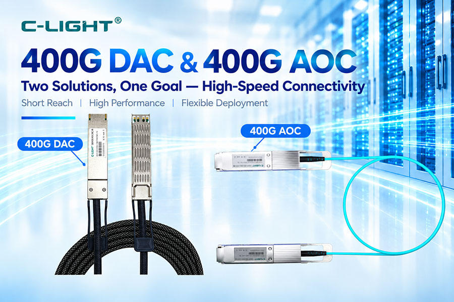
AOC integrates active optical electronics into a fixed cable assembly, while a 1.6T optical transceiver uses separate pluggable modules and fiber cabling. Optical transceivers generally provide greater cabling flexibility, while AOCs can simplify selected short-reach connections.
73. 1.6T Optical Module vs AEC
AEC uses active electrical components to extend or condition high-speed copper links. It can provide longer electrical reach than a passive DAC in some applications, while 1.6T optical transceivers provide fiber-based connectivity for architectures requiring optical transmission.
74. AI Data Center Network Architecture
A typical high-speed AI network may include GPU servers, NICs, leaf switches, spine switches, storage systems, and DCI connections. 1.6T optical modules can be used at high-capacity layers where the host platform and required reach support this generation of connectivity.
75. Switch ASIC Evolution
1.6T optical networking is closely linked to the evolution of switch ASICs and SerDes interfaces. As switching capacity increases, the electrical interfaces connecting the ASIC to optical modules must also support higher lane speeds and tighter signal-integrity requirements.
76. Network Topology and 1.6T
Higher bandwidth per port changes the design of network topology. It can reduce the number of physical uplinks needed for a given aggregate capacity, but network planners must also consider oversubscription, traffic patterns, switch radix, congestion, and failure domains.
77. 1.6T for Hyperscale Data Centers
Hyperscale environments can benefit from higher bandwidth density as infrastructure expands to thousands or more accelerators. 1.6T provides a path for scaling network capacity while controlling the number of high-speed optical ports required per switching layer.
78. 1.6T for HPC
High-performance computing systems require fast communication between processors, accelerators, storage, and network nodes. 1.6T optical interconnects can support high-bandwidth HPC architectures where the host equipment and optical infrastructure are designed for the required speed.
79. 1.6T for Cloud Infrastructure
Cloud data centers continue to scale compute and storage resources. Higher-capacity optical interfaces can support backbone, aggregation, and data center networking requirements where 1.6T is technically and economically appropriate.
80. C-LIGHT 1.6T Optical Transceiver Solutions
C-LIGHT provides 1.6T optical interconnect solutions for AI data centers, GPU clusters, HPC networks, and high-speed switching applications. Product architectures include OSFP-RHS designs and different optical configurations for different transmission distances and fiber infrastructures.
81. C-LIGHT 1.6T 2DR4
The C-LIGHT 1.6T 2DR4 OSFP-RHS solution is designed for single-mode fiber transmission up to 500m in the specified implementation. It uses eight 200G Ethernet channels and targets high-speed connections between AI server clusters and switching systems.
82. C-LIGHT 1.6T 2×FR4
The C-LIGHT 1.6T 2×FR4 OSFP-RHS solution is designed for longer single-mode connections up to 2km in the specified implementation. It uses LAN-WDM technology and a dual LC/APC interface for extended-reach high-speed connectivity.
83. Product Selection
The correct 1.6T optical transceiver should be selected according to bandwidth, host interface, transmission distance, fiber type, optical architecture, connector, power budget, thermal environment, management requirements, and interoperability.
84. Selection by Reach
| Required Distance | Potential 1.6T Architecture | Typical Fiber |
|---|---|---|
| Short reach | SR8 or similar parallel optics | MMF |
| Up to 500m class | 2DR4 or similar | SMF |
| Up to 2km class | 2×FR4 or similar WDM architecture | SMF |
| Longer reach | Other advanced optical architectures | SMF |
85. Selection by Network Layer
Short optical links inside AI clusters can use parallel multimode or short-reach single-mode architectures. Higher network layers and longer connections may require single-mode WDM or other optical architectures. The module should always be matched to the actual topology.
86. Selection by Power
Power-sensitive deployments should compare total module power, host power, power per bit, and thermal requirements. Lower-power DSPs, LPO architectures, improved lasers, and more integrated optical engines can all influence the final power budget.
87. Selection by Fiber Infrastructure
If the site already has multimode fiber, a short-reach parallel optical solution may be appropriate. Existing single-mode fiber infrastructure can support longer-reach 1.6T architectures. Connector and polarity compatibility must also be verified.
88. Selection by Host Platform
The host switch or NIC should be checked before purchasing the module. Confirm the supported OSFP or other form factor, electrical lane rate, power class, firmware, management standard, coding requirements, FEC mode, and optical configuration.
89. Common Deployment Mistakes
Common mistakes include selecting a module only by its 1.6T data rate, ignoring the host electrical interface, exceeding the specified optical reach, using the wrong fiber type, mixing incompatible connectors, overlooking polarity, assuming all 1.6T modules have the same power level, or treating different architectures as interchangeable.
90. Troubleshooting 1.6T Optical Links
Start with physical inspection and host module recognition. Then verify electrical lane configuration, optical power, fiber type, connector polarity, cable continuity, FEC settings, management data, temperature, and remote-end compatibility. For difficult problems, analyze lane-level BER and FEC counters to isolate the source of errors.
91. Future 3.2T Evolution
After 1.6T, optical networking will continue toward higher aggregate bandwidth and higher per-lane rates. The challenges will include electrical channel loss, optical modulation, laser bandwidth, thermal density, packaging, connector performance, and power efficiency.
92. Role of Optical Integration
As bandwidth rises, higher optical integration can reduce component count and improve optical density. Silicon photonics, advanced EML, VCSEL, hybrid laser architectures, and integrated optical engines are all potential building blocks for future transceivers.
93. Role of Low-Power Architectures
Power efficiency will remain a key design objective. LPO, improved DSP processes, lower-power drivers and TIAs, advanced lasers, better thermal design, and increased optical integration can help control the energy cost of future high-speed connectivity.
94. Role of Liquid Cooling
Liquid cooling may become increasingly relevant as AI rack and switch power densities rise. However, optical modules must be specifically designed and qualified for the selected liquid-cooling environment rather than assuming that standard air-cooled modules can be immersed.
95. Reliability at Higher Speeds
Higher lane rates require tighter manufacturing control and more comprehensive testing. Long-term reliability depends on optical component stability, electrical signal integrity, thermal cycling, packaging, connectors, and operating conditions.
96. Frequently Asked Questions
Q1. What is a 1.6T optical transceiver?
Q2. How does a 1.6T optical transceiver achieve 1.6Tbps?
Q3. Why do AI data centers need 1.6T optics?
Q4. What form factor is commonly used for 1.6T?
Q5. Does 1.6T always use eight 200G lanes?
Q6. What fiber does a 1.6T optical transceiver use?
Q7. What is the difference between 1.6T SR8 and 2DR4?
Q8. What is 1.6T 2×FR4?
Q9. Is silicon photonics used in 1.6T transceivers?
Q10. What are the main challenges of 1.6T optics?
Q11. Does a 1.6T module always consume more power than 800G?
Q12. Can LPO be used for 1.6T?
97. Summary
1.6T optical transceivers are an important next-generation connectivity technology for AI data centers, HPC systems, hyperscale networks, and high-capacity switching platforms. A common architecture uses eight 200G-class PAM4 electrical and optical lanes to deliver an aggregate 1.6Tbps. Different optical approaches, including VCSEL, EML, silicon photonics, parallel optics, DR8, 2DR4, and 2×FR4, can address different transmission distances and network architectures. At the same time, power consumption, DSP efficiency, thermal management, electrical signal integrity, optical link budget, packaging, interoperability, and manufacturing become increasingly important. As AI networks continue to expand, 1.6T optical transceivers provide a path toward higher bandwidth density and scalable optical connectivity while preparing data center infrastructure for future generations of higher-speed networking.
 >
>

 >
>
 >
>
 >
>
 >
>
 >
>
 >
>
 >
>